Assignment: Group assignment: Test the design rules for your 3D printer(s) Individual assignment: Design and 3D print an object (small, few cm) that could not be made subtractively. - 3D scan an object (and optionally print it).
For the 3d scanning I decided to try the Modela's scanning function. One of the Modelas in the Fab lab is set up with the scanning sensor, which is a contacting mesh-point height-sensing piezo unit with a probe that is 60mm long, with a 0.08mm tip. For a test piece I used a cluster of screwdriver bits and stuck it to the corner of the bed using the Modela's provided plasticine clay.
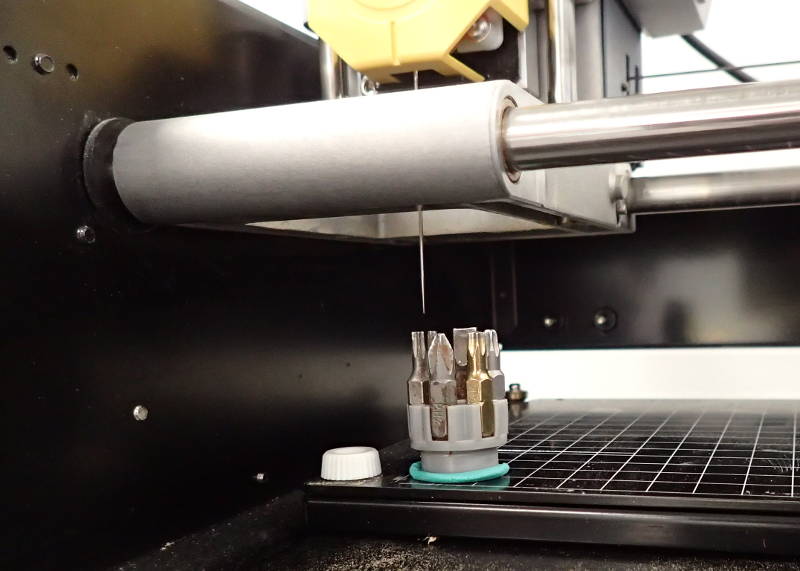
When setting the scanning area I set the maximum height by resting a sheet of paper on the highest part of the test piece and making the Modela lower the probe to it, so it would not waste too much time establishing a scanning area by scanning the air above the piece. I managed to botch this, so the scan took a bit longer than it otherwise would. I had the resolution set at 0.5mm, the machine is capable of a 0.05mm scanning pitch, but due to the way it handles memory, 0.5mm was the most the Fab lab's laptop could handle. It would also take lengthy pauses while buffering, but it always kept going, eventually.
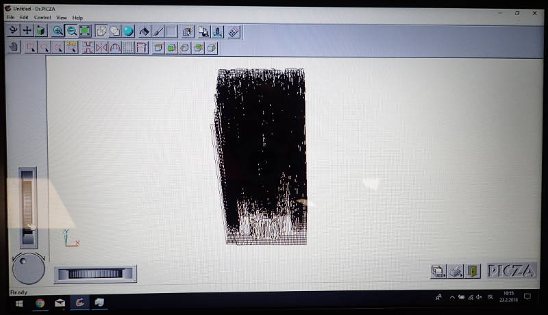
The following morning the scanning had finished and I saved the file as an STL file and opened it with Repetier host and sliced it with Slic3r. The model in the screen has a decidedly odd appearance, leading me to believe that some glitches have crept in during the scanning process. My own Modela MDX 20 has done some very good scans in the past, but that is directly connected to a computer using the original Roland serial connector, whereas the setup at the Fab lab is using a wireless connection to a Raspberry Pi that is connencted to the MDX 20 with a USB adapter, so there might be some bottlenecks on the way.
 Beton brut in PLA..
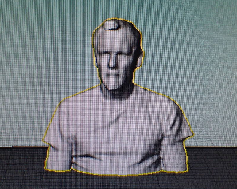
Instead I tried scanning myself using Reconstruct me with the Fab lab's Kinect sensor and printing the resulting model on the Replicator.
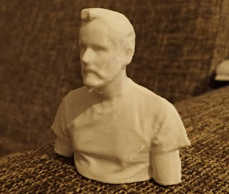 I chose not to use supports and the only critical area, under the chin, only had a few drooping strands that were easier to trim off than a support would have been.
Download a most handsome fellow.
For the 3d printing group assignment, we tested two different 3d printers, a Makerbot Replicator 2 that has been there since the lab started, and a new Ultimaker 3 Extended. We printed a 20mm test cube on both printers and I measured them, there was some slight overshoot on the vertical corners on them both, as they were printing at high speed, this seemed slightly more pronounced on the Makerbot, but was not directly comparable, as they were using different brands of PLA filament and the Makerbot was printing at a 0.3mm layer height and the Ultimaker at 0.2mm.
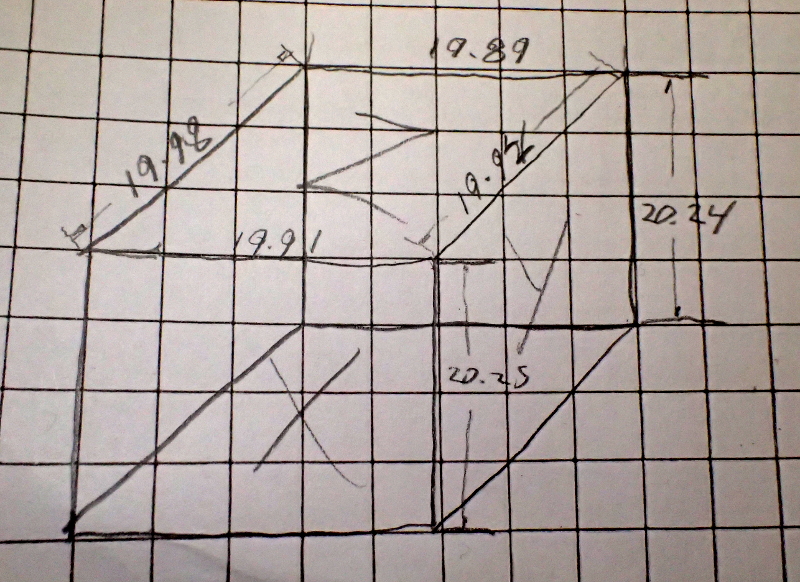 Replicator cube
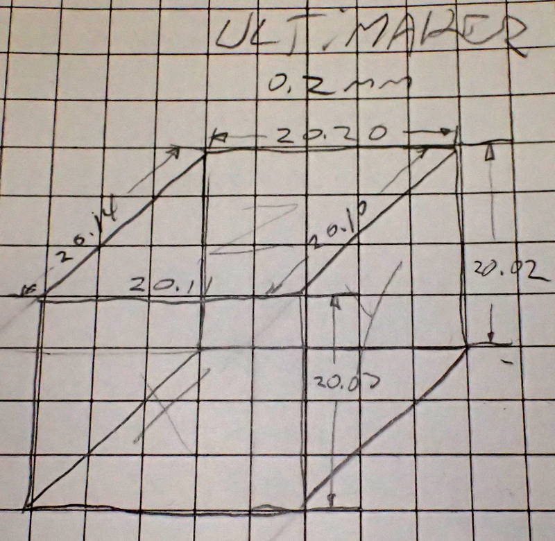 Ultimaker cube
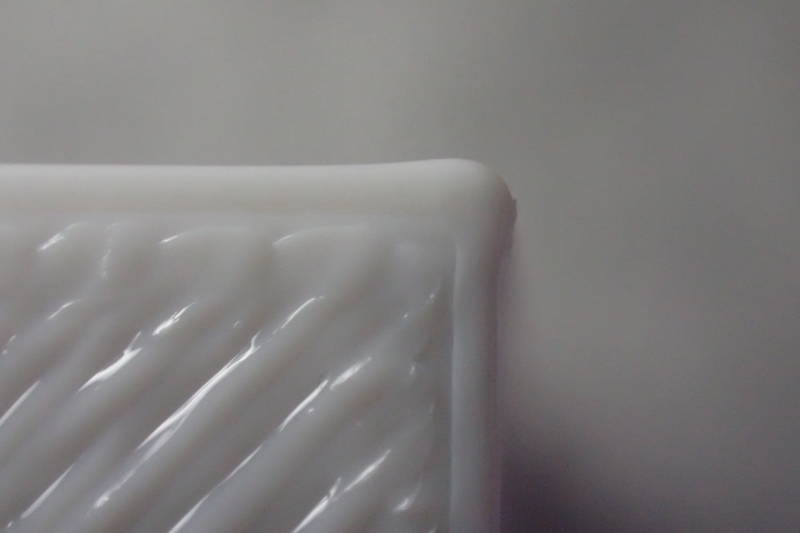 Replicator corner
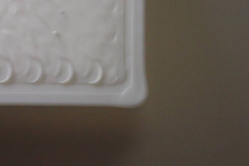 Ultimaker corner
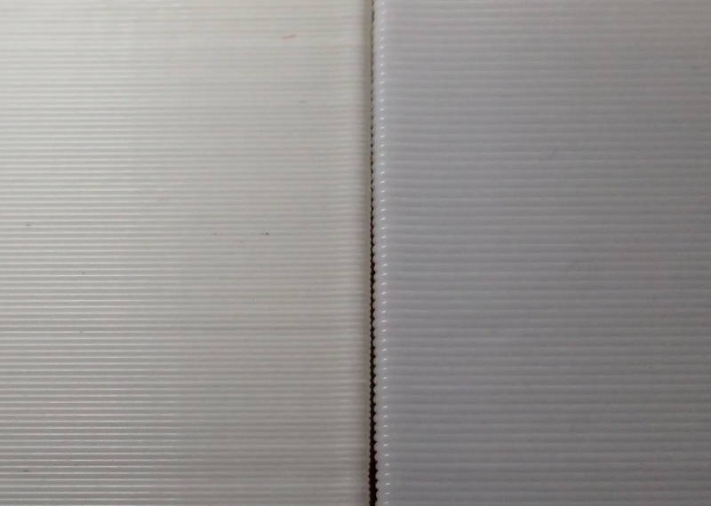 0.2mm vs. 0.3mm
When measuring the cubes, I measured from the top surface to avoid the oversize readings I would get from measuring the overshot corners.
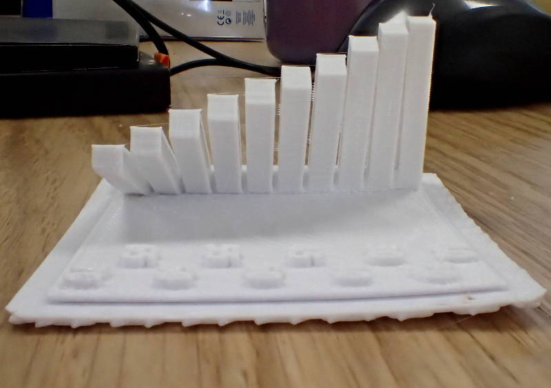
Arnar Dadi set up a tower test on the Ultimaker, to see the distortion that creeps in with increased height on narrow pieces.
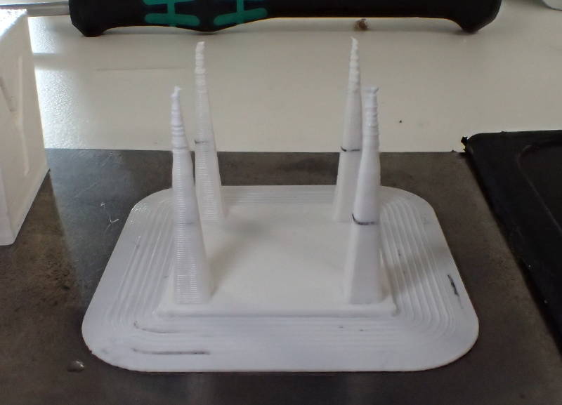 This was a table with four tapering spikes.
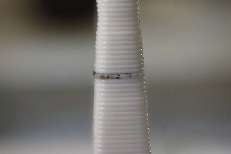 The first print showed a dark line on one level around the middle, so Arnar cleaned the extruder following Ultimaker procedure, and the second print came out clean.
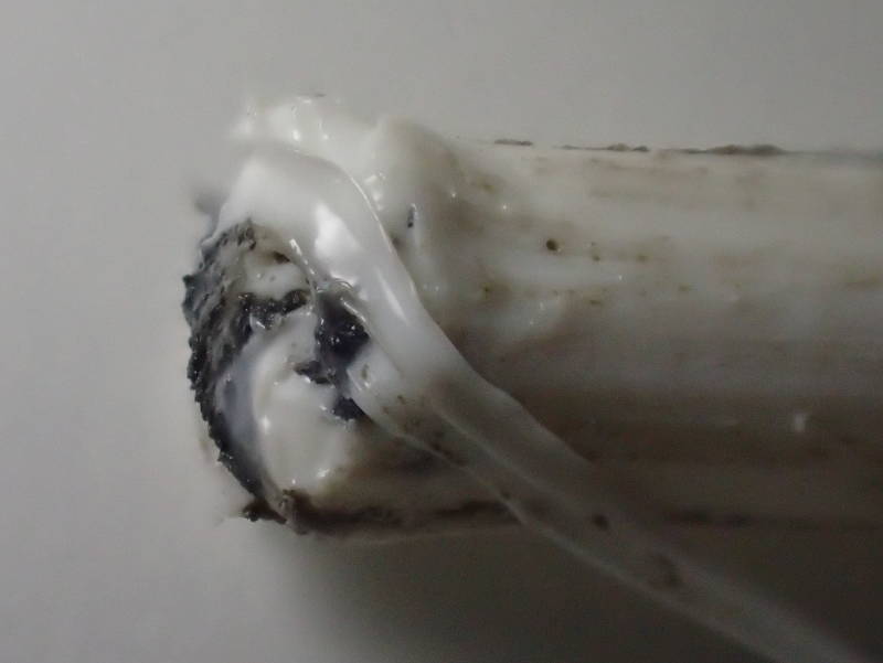 Dirt from extruder.
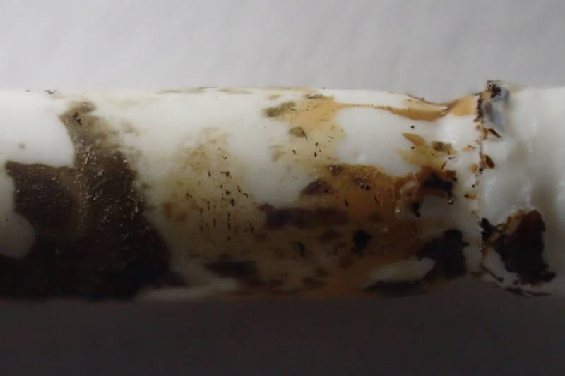 Possible residue from wood filament.
This accumulation of dirt in the extruder may have been caused by using wood filament, as the printer had been cleaned a month before.
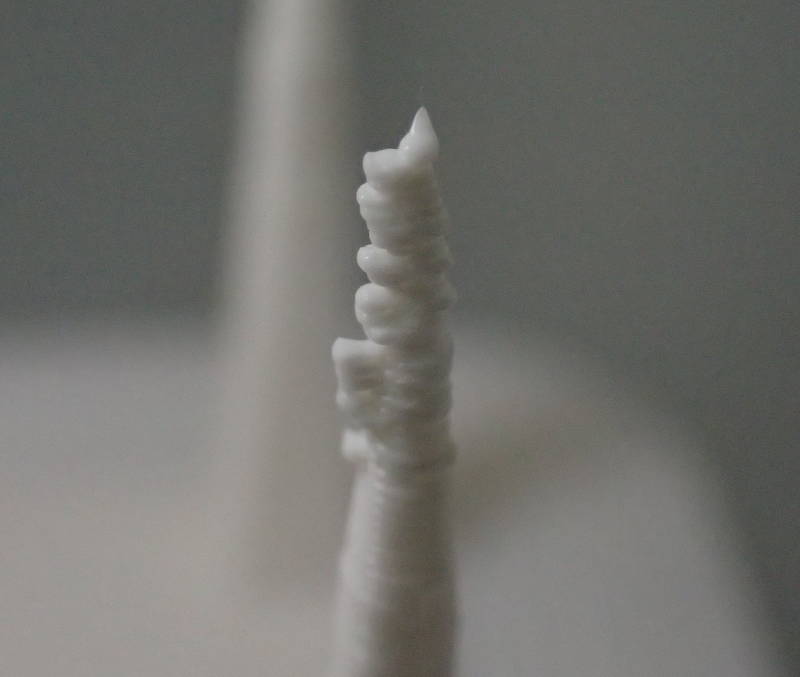 The four towers of the test piece became more deformed the higher and narrower they became, the printer was printing at too high a speed for the PLA to cool between layers.
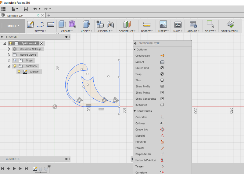
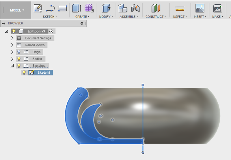
For the individual assignment, I used Fusion 360 to create a double-walled bowl by making a horizontal line for the bottom, a vertical line set as a construction line for an axis and some 3 point arcs for the sides of the bowl. I stopped the sketch and rotated the profile around the axis, giving me a bowl that I think is not possible to make in one piece by subtractive means, due to inaccessible internal cavities.
 Vessel cross section
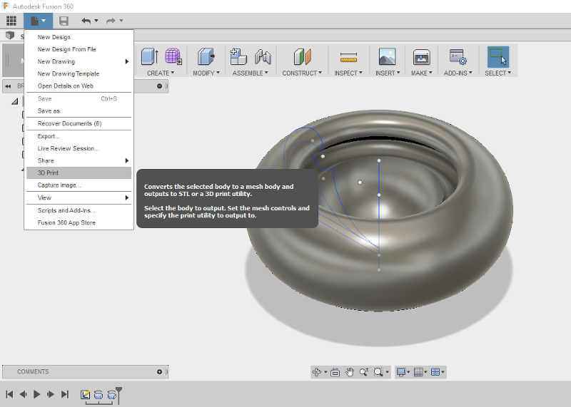 Exporting directly to 3d printing utility.
To export the model as an stl file for printing, it could not be exported as or saved as, but by choosing 3d print from the file menu it could export as stl and open the printing utility of choice, in my case Repetier host using Slic3r, which I used to save a gcode file, ready for printing.
When I tried printing the file, the Ultimaker would have none of it, so instead I saved the file as an stl, opened it with Cura, rotated and resized the model and saved it as gcode on a USB drive, which I took to the Ultimaker which got ready to print with no problems. The bowl's internal walls had profiles that might have given a 3d printer problems printing without supports and said supports would have been very hard to remove, due to inaccessibility.
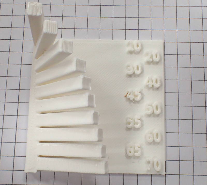 I aborted the print and downloaded a Leaning beam overhang angle test from Nani on Thingiverse and printed it out on the Ultimaker.
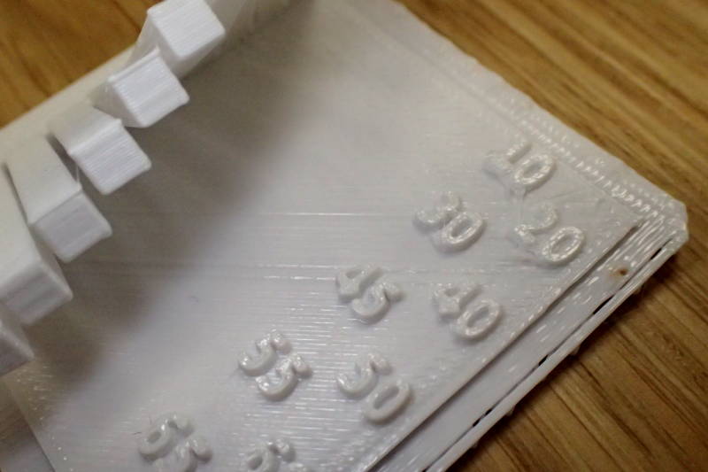
 It could handle a 45 degree overhang and could actually print the first 11mm of any of the overhangs. I also printed the same model on the Makerbot Replicator 2. I have never tried one before and I selected to print a raft, thinking this was a brim, to get better adhesion.
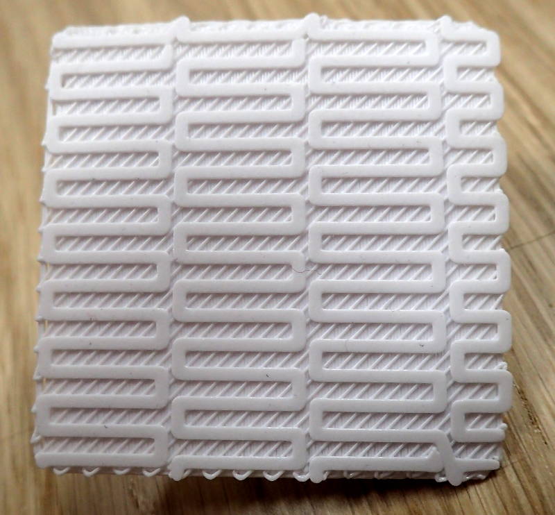 Instead the printer laid down a lattice underneath the model, guaranteeing that it could not stick properly to the bed and warped severely. I forgot to check the printing speed until after the print had started, it printed at 150mm/s, compared to the Ultimaker's 100.
 The model's top side looks decidedly rough, with strange artifacts and striations compared to the Ultimaker's consistently regular surfaces.
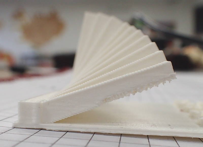
 It, however, passed the overhang torture test with flying colors, the underside of the beams showing no noticable drooping or distortion until the last one at 70 degrees.
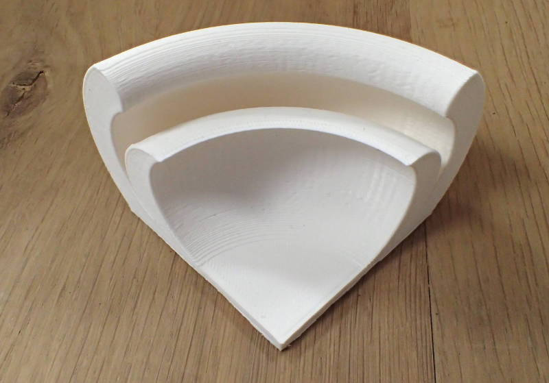
 I then redesigned the bowl to be easier for a printer to handle and Linda Wanders suggested I made a test section from it, so it could be printed showing it's cross sections, to see if the internal structure would print out well.
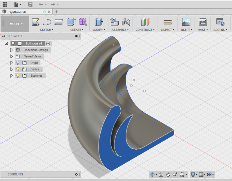 I made a 45 degree slice of the bowl and printed it out, leaving the Ultimaker to finish unattended.
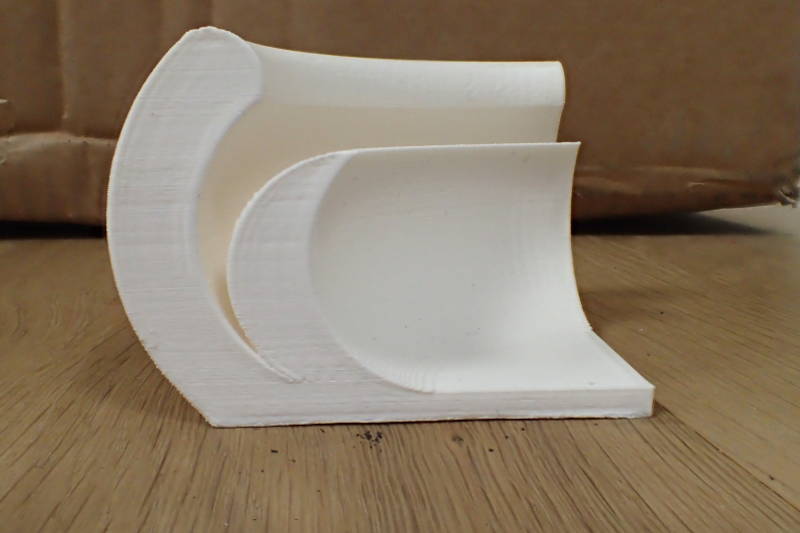 The next morning I arrived to find a perfectly printed piece and decided that I would use it as it is instead of printing a complete bowl, as this one-quarter section shows everything a complete bowl would have shown in terms of demonstrating a 3d printed piece that could not have been made with subtractive methods.
To embed this, I went to this Autodesk site, from where I could choose to share, embed or download all my Fusion 360 models in many different formats. Right click on my page and select Inspect element to see how to embed models like that.