Group Project
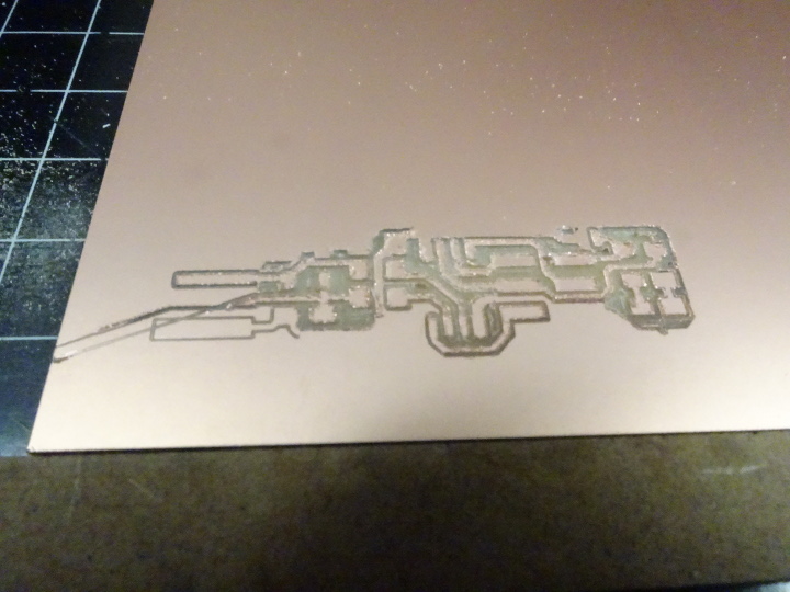
For this weeks group assignment we made a test with the Roland Modela RX-20 to see how the workflow and how well it mills. The first trace was not good since the bit was worn out and we needed to replace it.
It's good to see if the bit sits nicely in and is about halfway in or more.
.jpg)
Also the bit moved to the corner while it was milling but for what reason I don't know, after that we cut it out and it went smoothly. Next we made the line test to see what the limit of the Modela is. The bed was slighty tilted as you see in the picture.
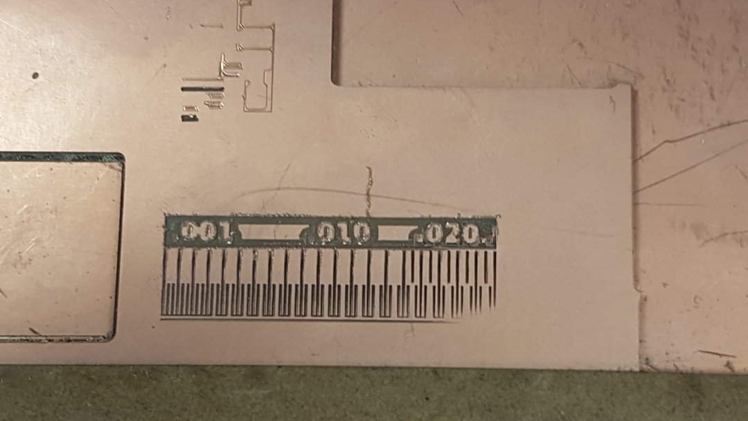
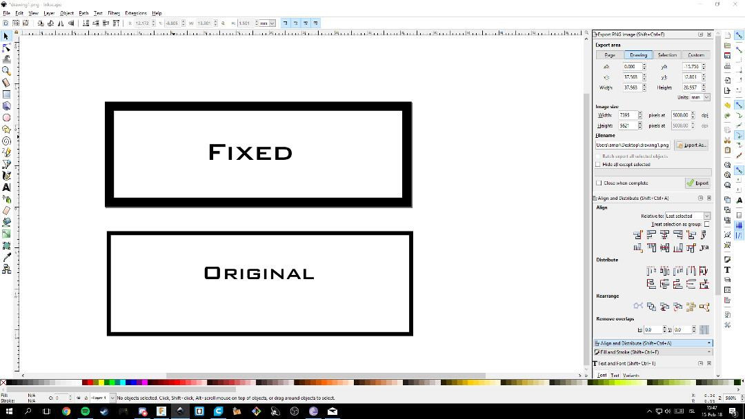
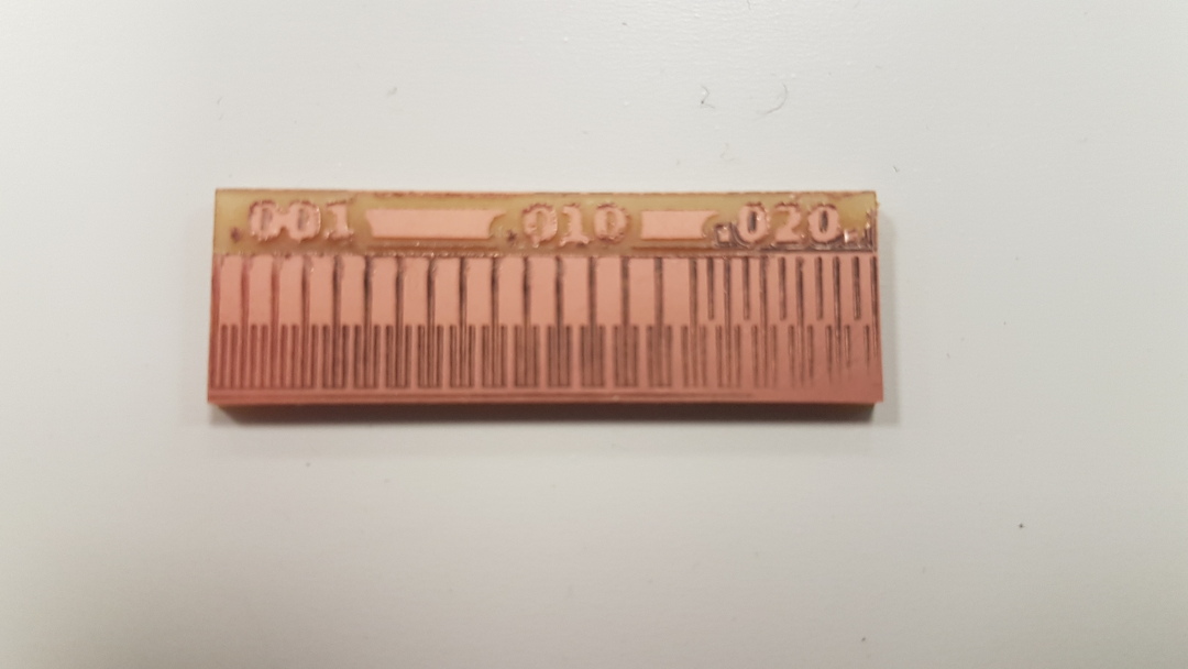
You can also see that the bit is worn out on the outline of the numbers, they were really rough. When it came to cutting out the test it didn't cut out the bottom of the part. We tried editing the sketch, I opened Inkscape and learned that it has export png settings wich is the format we use to mill out the circuit-boards and after fixing the sketch we were able to cut it out correctly.
Sending to Modela
To mill out the board we use Fabmodules.org. We use PNG images for the site to read what we want to do, next we select Roland mill (.rml) and next we select either PCB traces (1/64) or PCB outline (1/32). Next we select the machine we use and put in the xyz starting point and to see where that location is you press "move to xyz0" and when you find the correct location press calculate and before sending it check if it calculates everything correctly. We use a Raspberry Pi 3 that is connected to the internet and the Modela so we have to type in the address that the Pi has and press send to mill the circuit.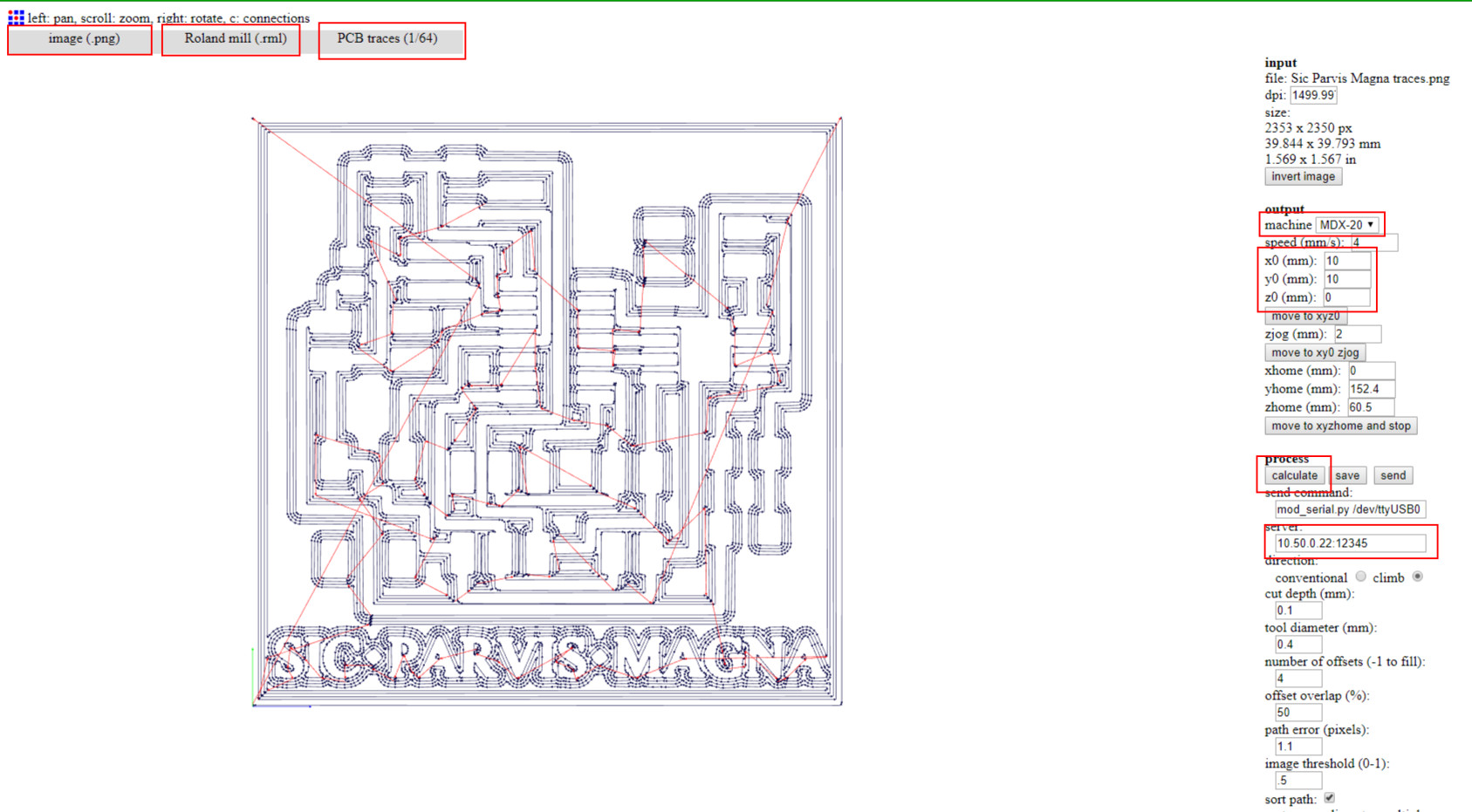
Programmer
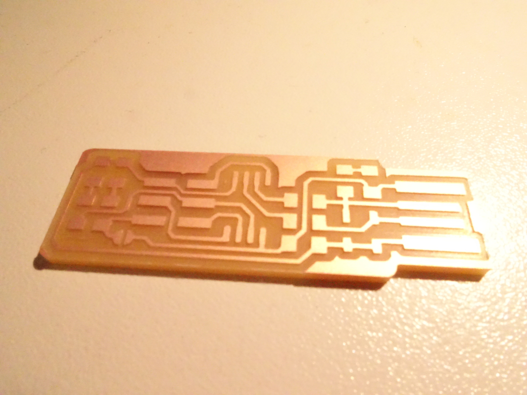
This weeks individual assignment was to make a in-circuit programmer. My first test of milling I made a mistake of reloading the fabmodules site after milling out the traces and forgot the position of the circuit so it cut out wrong.
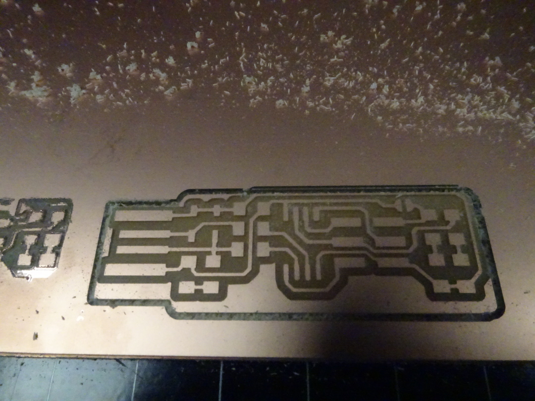
The next time it cut out nice and smooth.
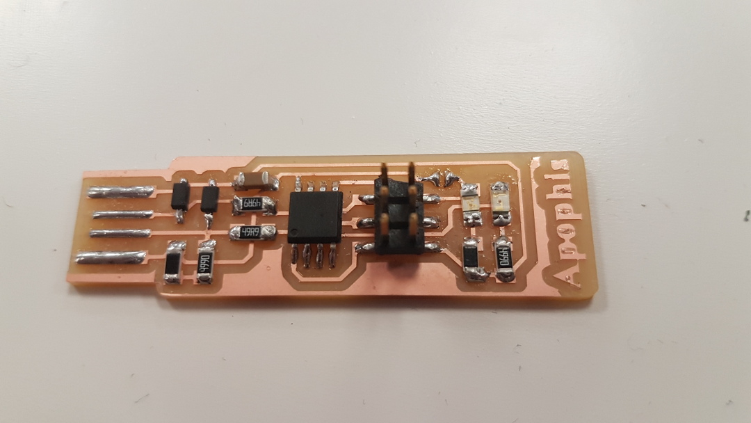
Next was to solder the electronics onto the board. Since it was my first experience soldering small electronics I didn't know how to mount them onto the board so I searched on youtube and found
this video
explaining how to properly solder the parts onto the board. The first board I made had the LED's wrong and for the life of me I tried using the copper braid to de-solder them to rotate them but was unable and also I wanted to practice soldering so I made another one and gave it a name.
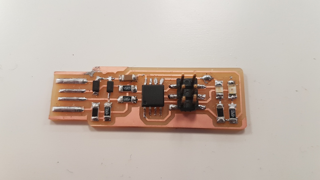
When the other board was finished I plugged it in and there was light so next up was to program the programmer. I followed
Brian's guide to building the FabTinyISP.

I tried following the instructions for the software installation for
windows 10
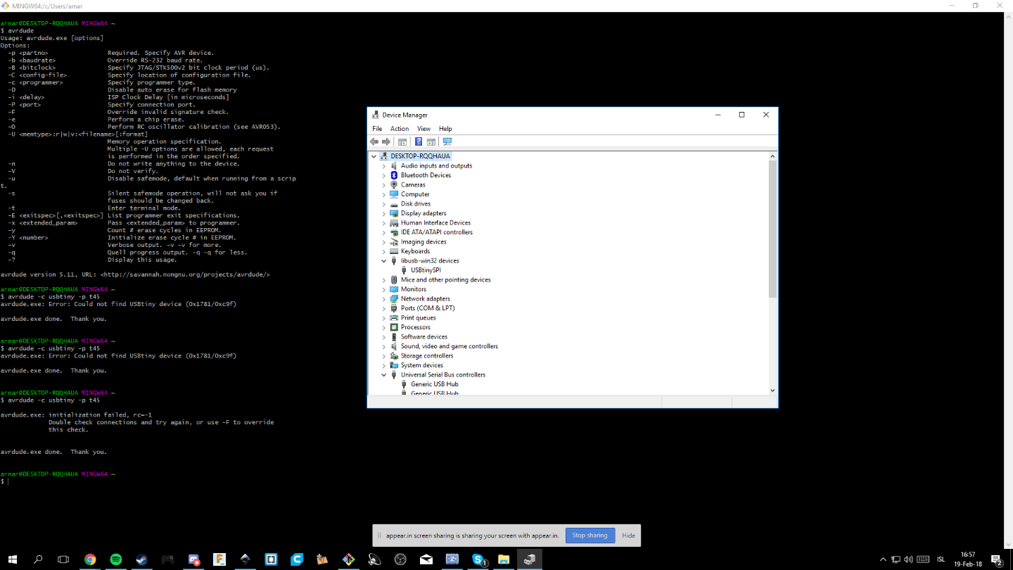
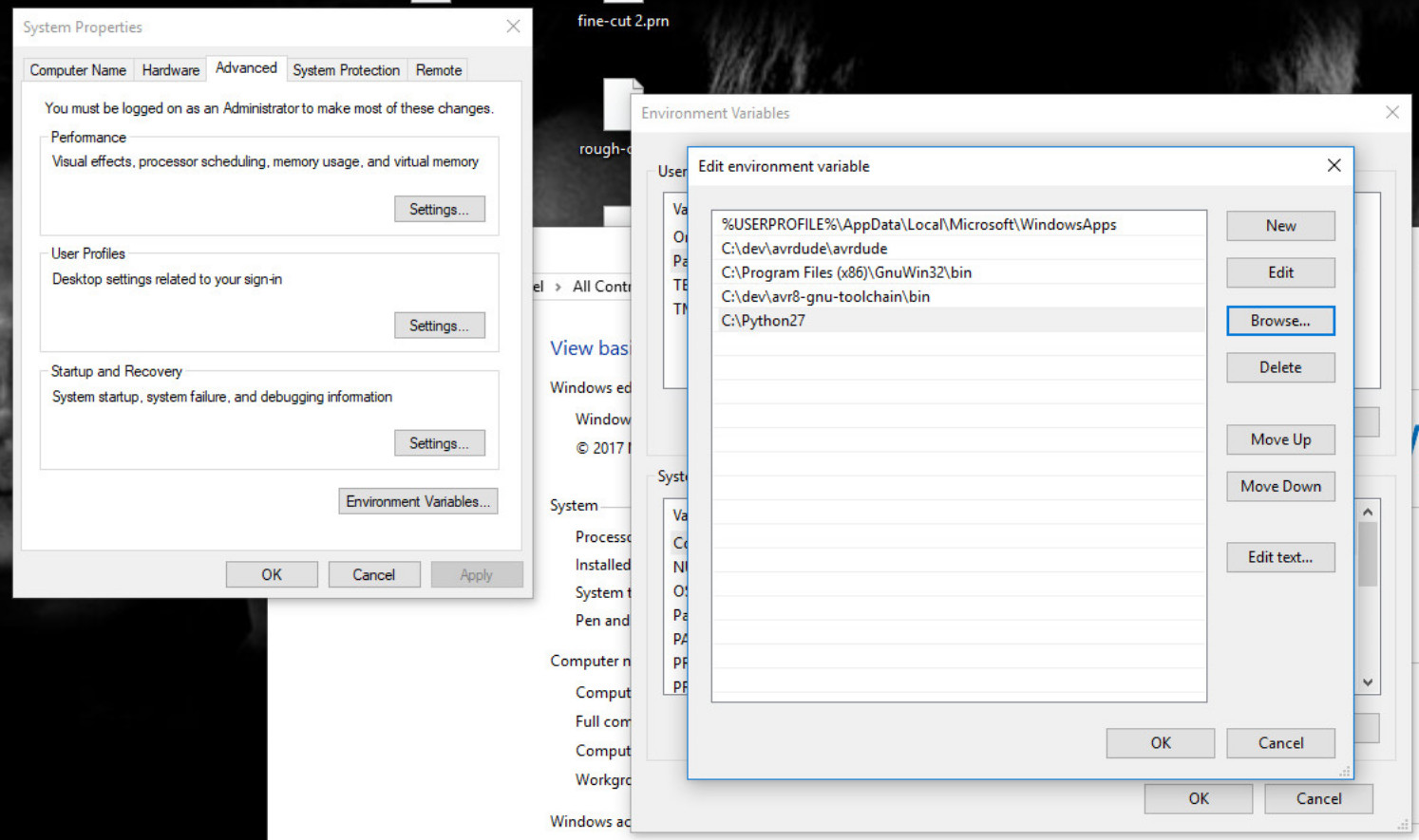
and made a mess of things on my laptop and after hitting a wall I ended up going to my pc and be more organized and go slower through the instructions. After a while my brain just couldn't cope so I ended up contacting master Bas and have him go through the setup with me. First we needed to locate the programmer. And after that I got error 193 and that was because I wrong toolchain program so after that we went after the instructions and everything went smoothly and we were able to program the programmer.
The correct toolchain is located
here
and is at the top at AVR and ARM Toolchains(C Compliers). Next is installing the
GNU Make,
downloading
avrdude
and unzip it in c:\Program Files, updating the path,
 installing
Zadig
and then the only thing left is program the programmer.
installing
Zadig
and then the only thing left is program the programmer.