Networking & Communications
Spoon networking
After I switched to what I wanted to make for my
final project
I continued with my electronics assignment. I chose to work with a commercial board because the
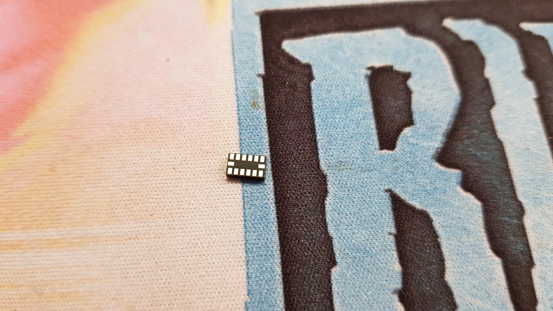
SMD accelermeter
that we have in the Lab´s inventory has its solderingpads on the bottom. Which means that mounting this on a locally made board is only possible via reflowing technique which our FabLab does't have the suitable equipment for that available.
 Then I checked if it would work with an arduino board which worked but when we switched to an ATtiny and it didn't work so I looked into the
Arduino Wire library
to see if we could communicate with arduino code from the accelerometer to the ATtiny44 but that didn't work so we found
USI wire library
which works with most of the ATtiny family. I learned that #include with "" is local and connects a file to the code and <> is global wich uses a code that is within the arduino library and you can get different ones on the internet.
Then I checked if it would work with an arduino board which worked but when we switched to an ATtiny and it didn't work so I looked into the
Arduino Wire library
to see if we could communicate with arduino code from the accelerometer to the ATtiny44 but that didn't work so we found
USI wire library
which works with most of the ATtiny family. I learned that #include with "" is local and connects a file to the code and <> is global wich uses a code that is within the arduino library and you can get different ones on the internet.
We got rid of most the
original code
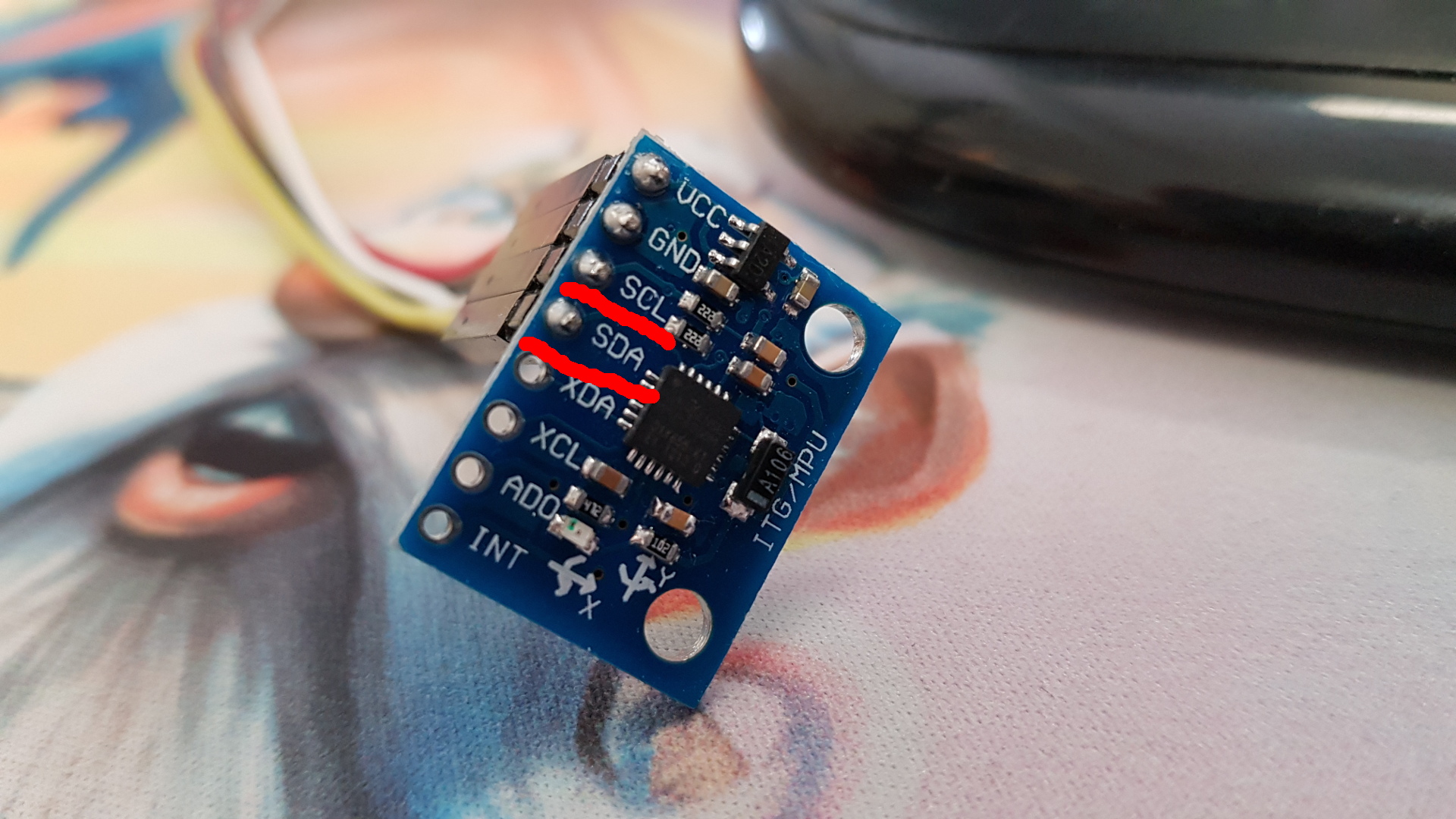
and replaced all "floats" to "int16_t" wich means integer (whole number, no commas) that is 16 bit. We also took out everything related to the gyro motion and the reason why is that the microcontroler has a limited memory and float takes alot of it and also we don't need unrelated code taking up space. We checked the datasheet for two wire mode (I²C, TWI or USI) to see if the accelorometer would work with the ATtiny'44 and it has SCL and SCA. The I²C protocol defines basic types of transactions, each of which begins with a START and ends with a STOP. It has a master that can send commands to a slave and can also read what the slave sent to it.
 After coding more and problemsolving we connected the accelerometer to a board that I made in
week 9
and that contained an ATtiny'44 and it had an 20MHz crystal so we set the clock from 8MHz internal (that's the how fast the controler can complete an instruction) to 20MHz external. Checking on the correct baud-rate is also important since that is the speed that is how fast the controller is sending/recieving/changing signals. After all that we ran coolterm to see what the controller was sending/if it was doing anything.
After coding more and problemsolving we connected the accelerometer to a board that I made in
week 9
and that contained an ATtiny'44 and it had an 20MHz crystal so we set the clock from 8MHz internal (that's the how fast the controler can complete an instruction) to 20MHz external. Checking on the correct baud-rate is also important since that is the speed that is how fast the controller is sending/recieving/changing signals. After all that we ran coolterm to see what the controller was sending/if it was doing anything.
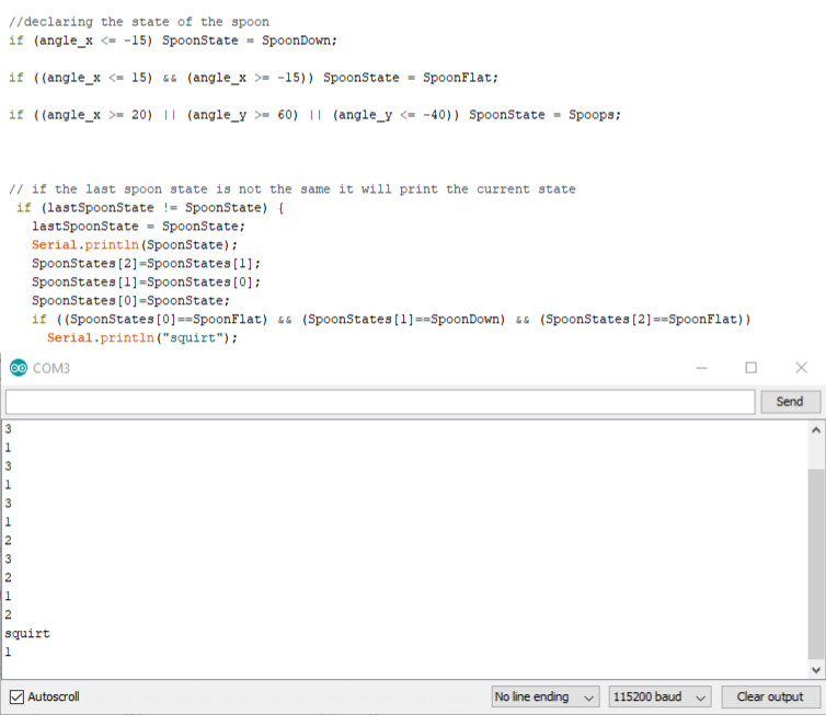
Next we made a code to display numbers for different states and after a certain flow it would "print" squirt and that is the command to make the pump rotate.
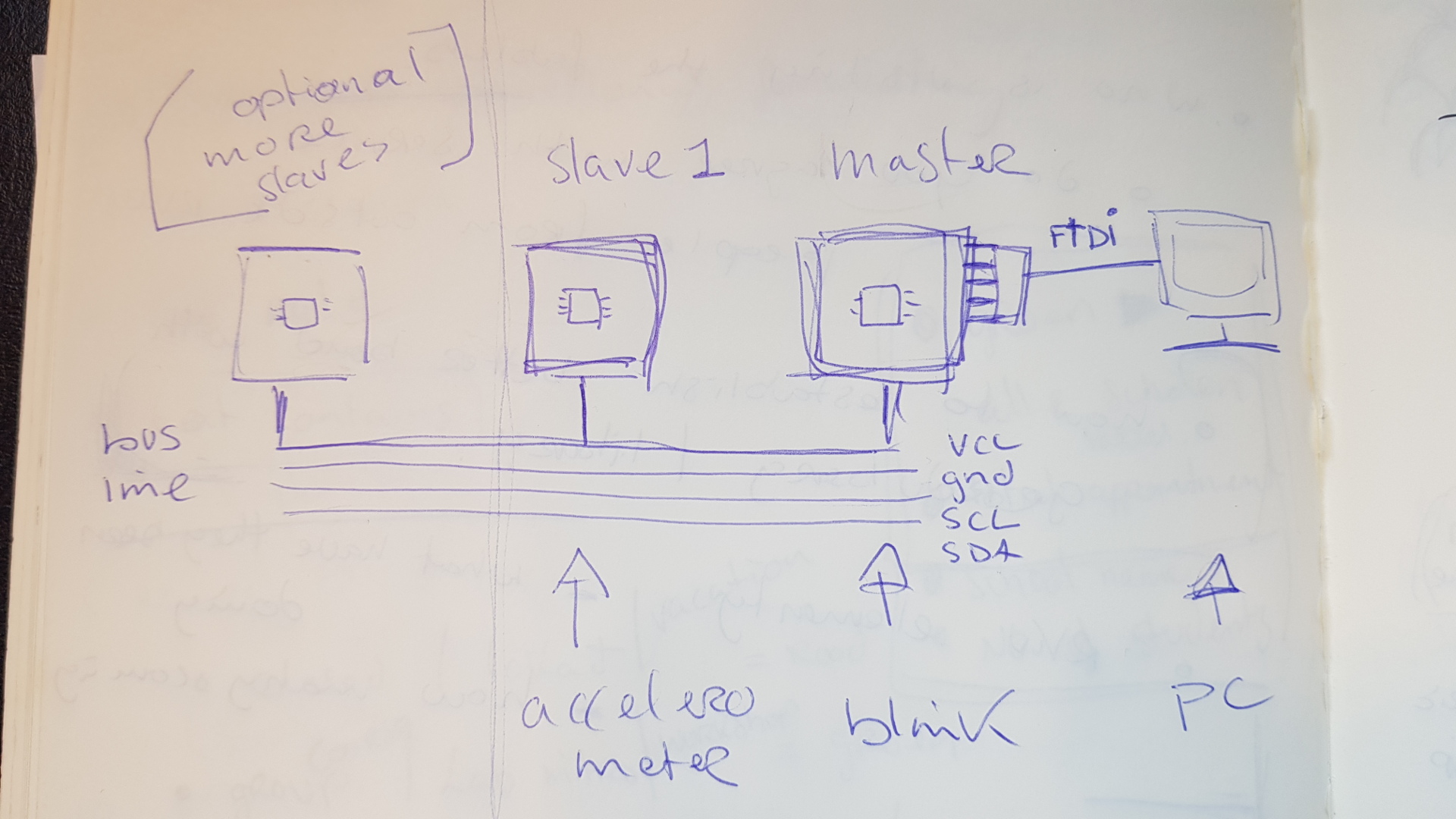
 There is a processor in the accelerometer and it's preprogrammed. The accelerometer is the slave and it measures the tilt and sends it to the master. The blink board is the master and it listenes to what the accelerometer is sending, then sends the values to my PC. The accelerometer sends the values with the I²C protocol and for that the master needs a pullup resistor which the ATtiny44 has (blink board). And it goes up to 3.3 volts which is necessary for the accelerometer.
 Arduino code For Arduino Board
PCB Outline File
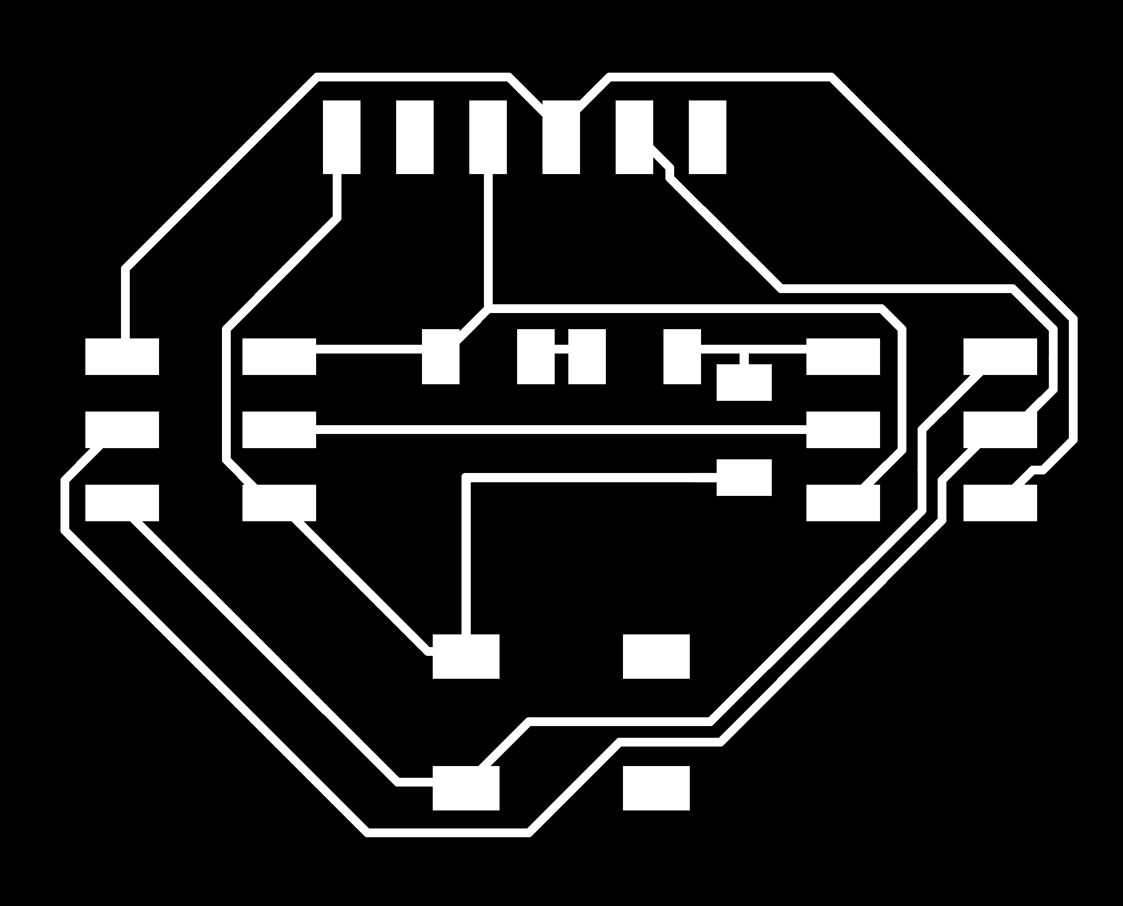
PCB Traces File
Arduino Code For ATtiny44
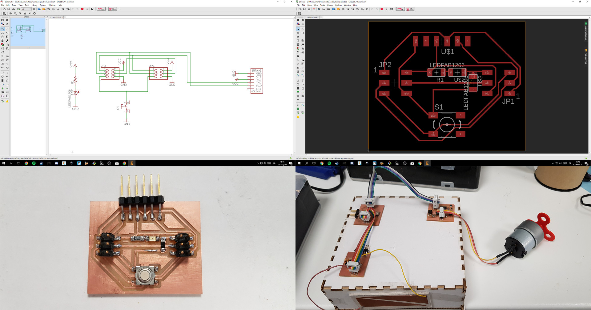
For networking & communications week I started making a board that connects with FTDI headers and 2 6 pin headers so it can transmit power, ground, rx and tx between boards. I also connected a LED on the board to see if there was power and accidentally I connected them in the opposite direction so I had to resolder that.
 Traces
Outline
Eagle Board file
Eagle Schematic file