Designing PCB
This week I continued to work on my final project. I will make a robot that just moves around on 2 wheels and avoids crashing into things. On input devices week I built the final project board, attached a HC-SR04 sonar to it and tested it with Neil's code.
This week I will continue to work on the output part of the robot, adding a board with 2 A4953 H-bridge motor drivers and two pin headers for 2 DC motors that move the wheels. I can hopefully then connect this board to the final project board, and test that it works with Neil's existing code.
The basic principle of work for the H-Bridge according to the datasheet are as follows :
- Designed for pulse width modulated control of DC motors
- Capable of peak output currents to ±2 A and operating voltages to 40 V.
- Input terminals provided for use in controlling the speed and direction of a DC motor with externally applied PWM (Pulse-Width Modulation) control signals.
- Internal synchronous rectification control circuitry provided to lower power dissipation during PWM operation.
- Internal circuit protection includes overcurrent protection, motor lead short to ground or supply, thermal shutdown with hysteresis, undervoltage monitoring of VBB, and crossovercurrent protection.
Here is the pin-out diagram, copied from the datasheet
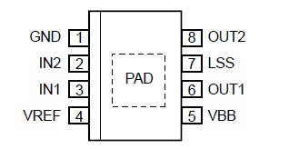
GND: Pin 1 is Ground
IN1: Pin 3 is Logic input 1
IN2: Pin 2 is Logic input 2
LSS: Pin 7 is Power return – sense resistor connection
OUT1: Pin 6 is DMOS full bridge output 1
OUT2: Pin 8 is DMOS full bridge output 2
VBB: Pin 5 is Load supply voltage
VREF: Pin 4 is Analog input
PAD: Exposed pad for enhanced thermal dissipation in the bottom of the component
To get started I studied Neil's hello.H-Bridge board layout, components photo, and dc motor video. Neil had also included sample C code and a makefile to program the board in the output devices week.
I looked at neil's board for reference, and discussed this week's project with out Local instructor Juha-Pekka, after that I started to tinker with Eagle on my own. It was a process of trial and error. For the process, I followed my own documentation from week 5 (electronics production).
Below is the first version of my board
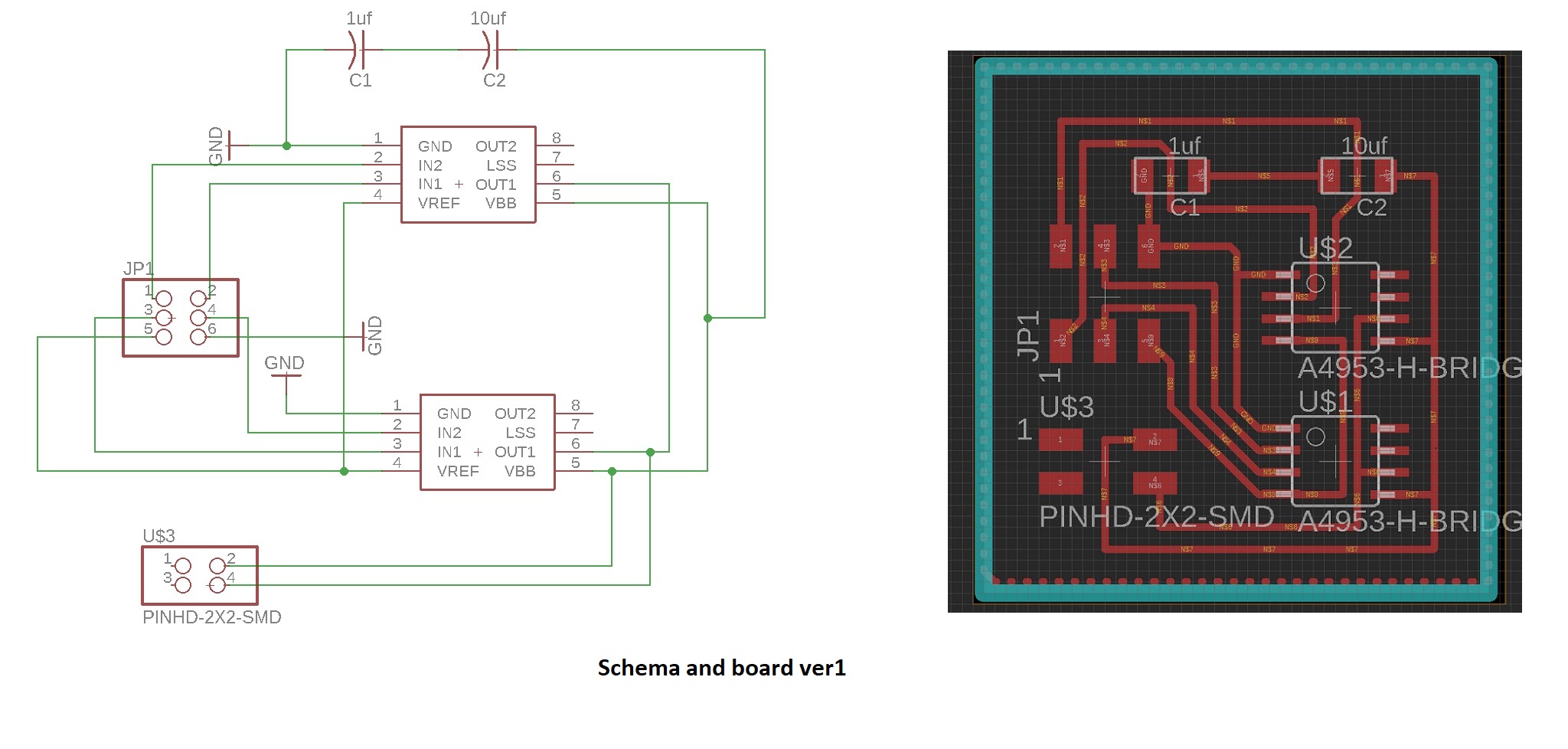
And the partlist

At this point I was veeery proud of myself, thinking that I have gotten a hang of this. Oh the error of my ways.
As I proceeded to show my design to Ivan, our FabInstructor, he pointed out quite a fatal flaw. I had not understood how the H-Bridge connects to the motors, and had therefore not included the pin headers to connect motors to the board. So back to the design board it was. This time I took a look at Ivan's documentation from last year on how to connect the pin headers for the motors to the H-bridges.
Here is the second version of my output board.
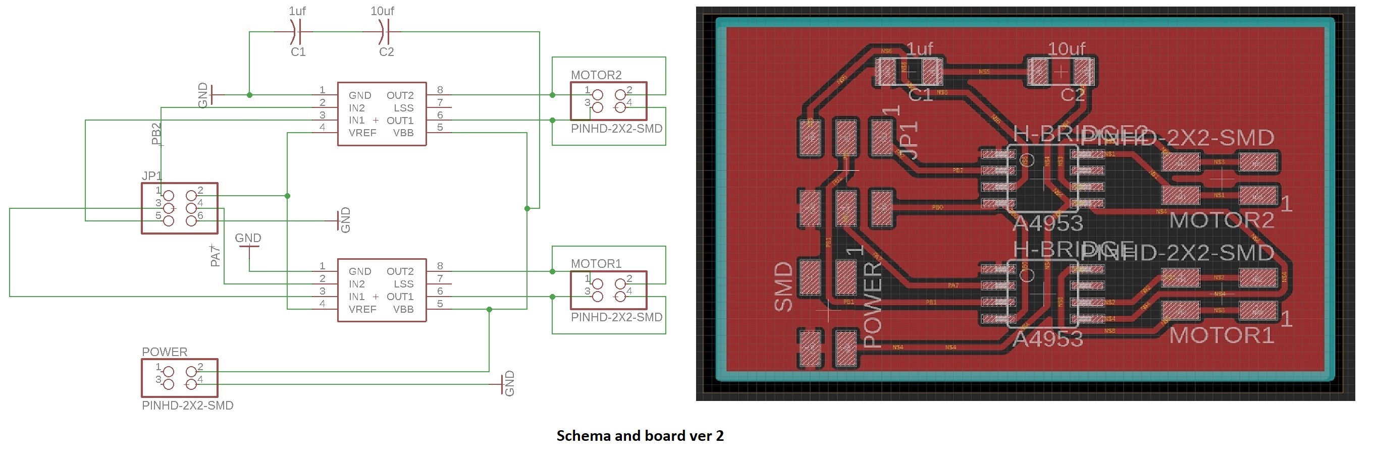
And the partlist

Again. Very proud of myself. Having been able to find information and correct my errors. I even proceeded to mill out this version of the board.
Too soon. When I talked to Ivan, I found out that I had not inspected the H-Bridge datasheet closely enough when drawing my board. I had drawn lines to go underneath the H-bridge component in Eagle, because it was possible to do so. The bottom of the component has an exposed thermal pad, and when working the board, it would have caused a shortcircuit.
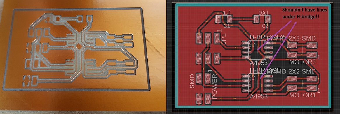
So, third time being the charm, I returned to the drawing board. The schema and the components were OK, I just needed to do the routes again for the boad that do not go underneath the H-bridges. I worked on this quite a long time, but unsuccessfully, therefore I decided to add a jumper to the design to take care of my last nuisance.
Here is the final version of the output board
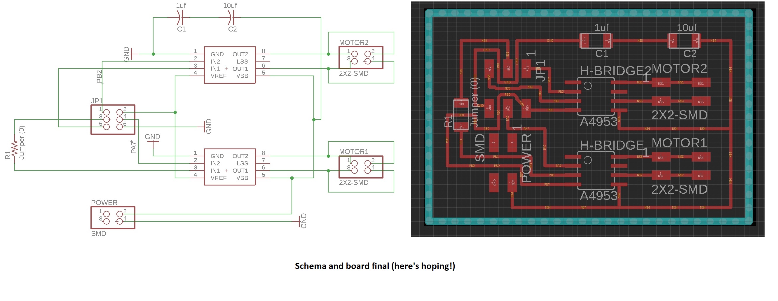
and the partlist

This time, I had really succeeded, and after the local instructors gave their OK, I proceeded to save the traces and outline to my computer as png files.
Here are my design files
- H-Bridge board .sch schema file
- H-Bridge board.brd design file
- Traces .png file
- Outline .png file
Machining the PCB
When machining the board I used the same workflows already identified on week 5 of Fabacademy.
I went to fabModules website to work on the traces and outline .png files, to include your own milling machine specifications so that the board comes out right.
First I imported my traces file,
- I selected the input format to be png.
- I selected the output format to be for Roland Mill (rml), which is the brand of milling machines that we have at FabLab Oulu.
- I specified the I am doing a PCB traces
- I selected what Roland Mill machine I am using - It is SRM-20. When I select this, the FabModules gives me some default settings for the machine.
However, as different machines have different settings, mill heads etc. I then proceeded to modify those settings according to what our local instructor advised us.
- I changed the x,y and z values from 10mm to 0mm.
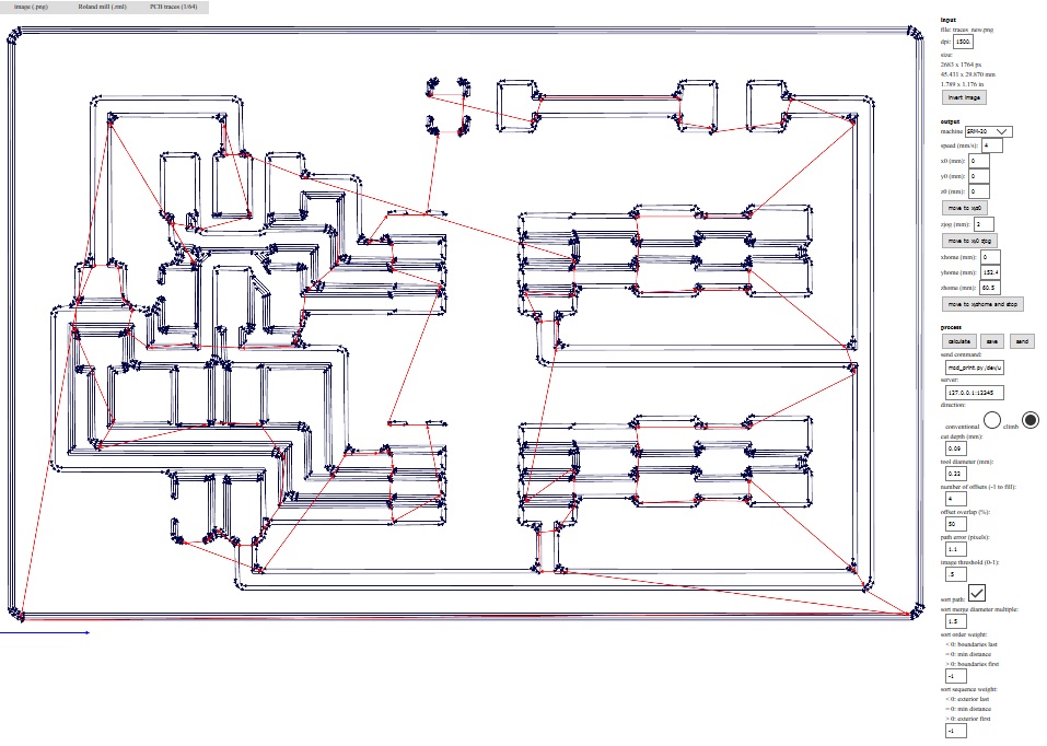
- I also did some slight modification to the process settings this time, according to what were the last "succesful" settings used by other FabAcademy students. advised I used cut depth 0.09mm and tool diameter 0.22
--> I proceeded to press calculate, and got the following result that shows me milling lines and offsets. I saved it to my computer as a .rml file
Next it was time to start working on the outline file.
- I again defined that the input file is image (png)
- I then defined that the output format will be Roland mill (rml).
- I specified that this time I am doinf PCB outline.
- I selected the output machine to be the SRM-20 again, and changed x,y and z values from 10mm to 0mm.
- I also did some modification to the process settings: Tool diameter was changed to 0.9mm, cut depth was set to 0.6mm.
--> Pressing calculate gives me a picture that shows me milling lines and offsets. At the first try it gave me this picture, which shows two sets of milling lines like this:
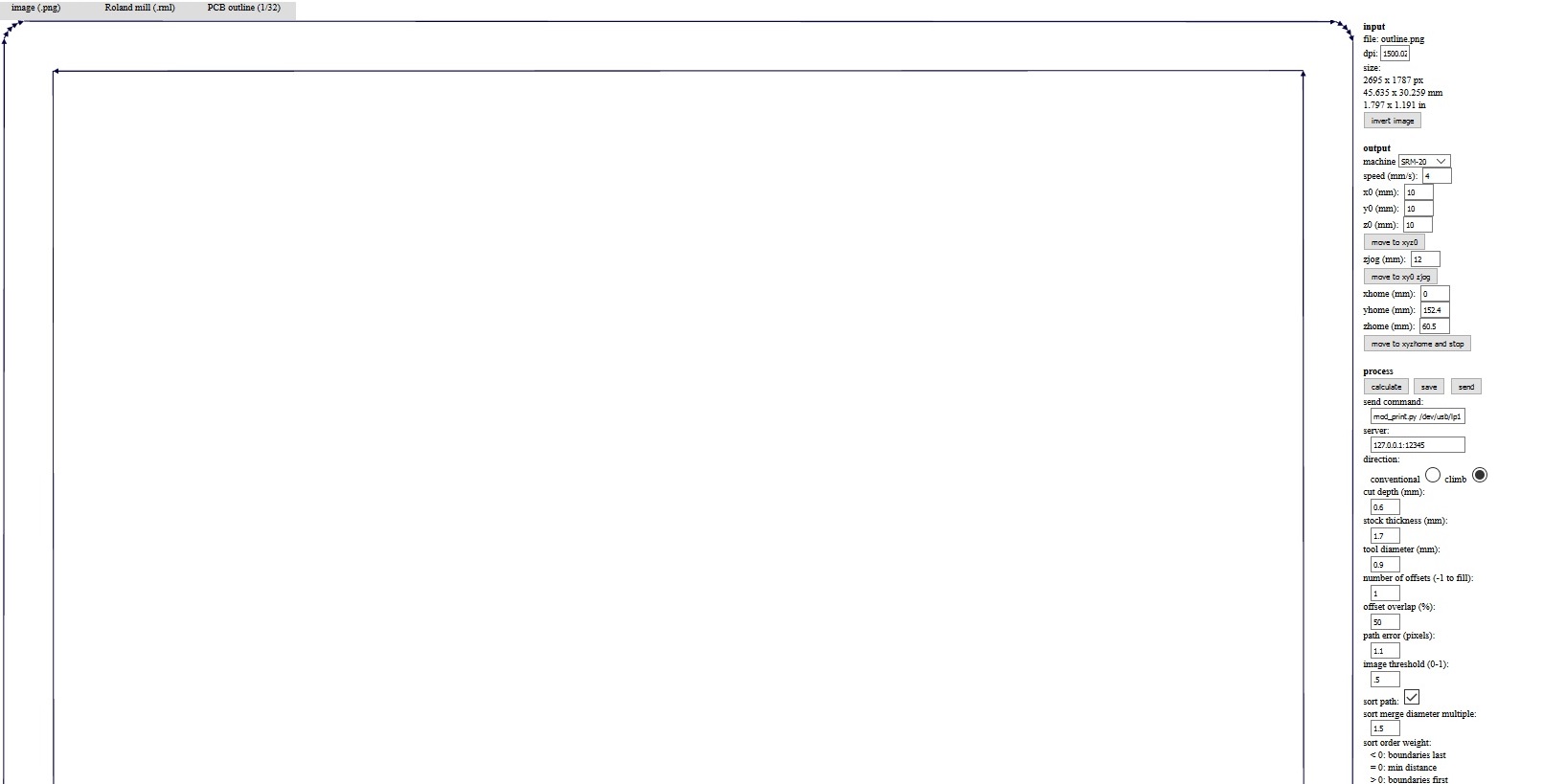
This is of course unnecessary. The board does not have to be cut out twice. My local advisors told me that I had somehow saved the outline png file with the colours inverted, and to correct this I was advised to press the "invert image" button on fabmodules, and to try again. This worked.

I proceeded to save the resulting file to my computer as a .rml file
Here are my milling files
- Traces .rml file
- Outline .rml file
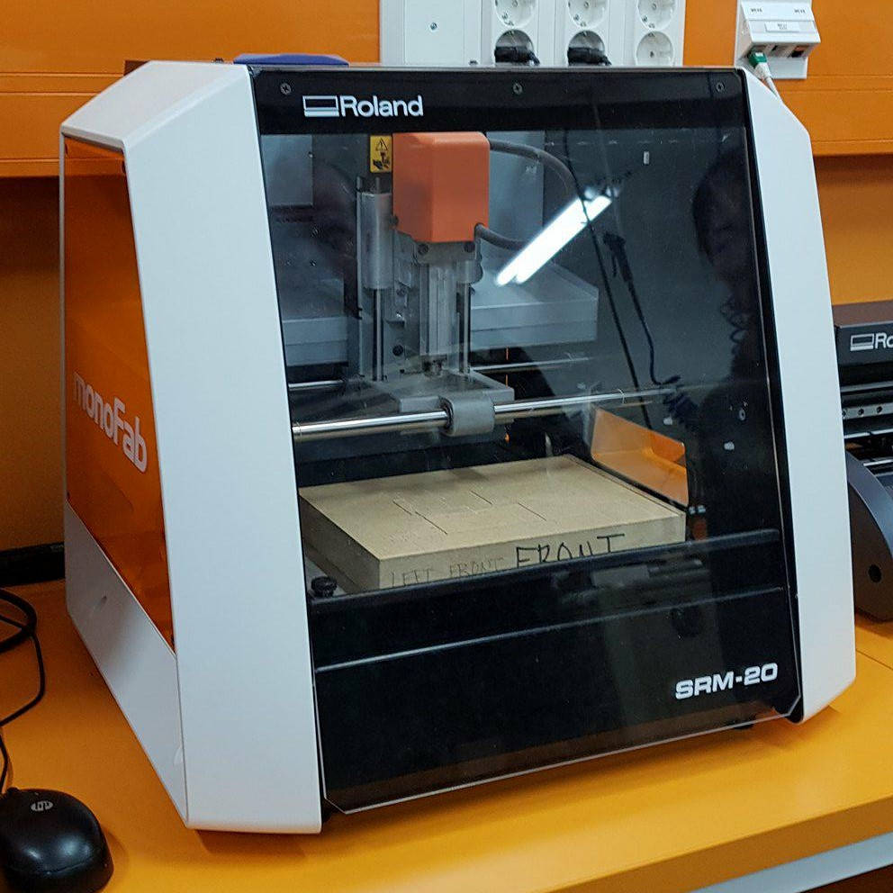
I took my rml trace and outline files and headed towards the milling machine and the computer that it is controlled with. Here is the Roland Mill SRM-20 that is used in FabLab Oulu.
- I removed the inner baseplate from the machine
- I took a fresh copper plate that I will be milling my hello world PCB into, placed double sided tape on it's bottom, and secured it on the baseplate.
- I put the baselate back in the machine and secured it to place, and closed the lid of the machine
- I put in the milling head to the milling machine with the help of the allen key
Next I started to work on the computer.
- I opened up the application that you use to control the machine. the UI of the Roland Mill at FabLab Oulu is called VPanel for SRM-20.
- I used the XY movement keys to move the milling head to the front left corner of the copper plate, and then hit the X/Y button (9) to set the origin.
- I used the Z movement keys to lover the milling head close to the copper plate, then used the allen key, loosen the milling head so that it touches the copper plate, and then tighten it back on. Then used the Z movement keys to lift it a bit from the plate and then hit the Z button to set the Z position of to the base point.
--> Once I got the coordinates fixed, I pressed cut, cleared the cutting queue by pressing "delete all", and uploaded my own traces file there. I press the output button to send my file to the machine to be milled.
- When the traces were milled, I vacuumed the board (without removing it from the machine), and set out to cut the board out of the copper plate.
- First I changed the proper milling head to the machine. We used the flat headed 0.8mm tool. Then I repeated the some of the steps described above for the outline file:
- I used the Z movement tool to lover the milling head close to the copper plate, then used the allen key, loosen the milling head so that it touches the copper plate, and then tighten it back on. Then used the Z movement keys to lift it a bit from the plate and then hit the Z button to set the Z position of to the base point.
--> once I got the coordinates fixed I pressed cut, and a dialoque window opened up. I cleared the cutting queue by pressing "delete all", and uploaded my own outline file there. Next I pressed the output button to my file to the machine to be milled.
A photo of my outline being milled

Once the outline was cut, I vacuumed the board again, and carefully removed my PCB from the machine. (As there usable copper board still left, I left it attached to the baseplate).
Soldering the PCB
After removing the PCB from the machine, I rubbed it with steel wool.Next it was time to head to the treasure closet to scour all of the components needed for the board. I took the list with me and got:
--> 1uf Capacitor
--> 10 uf capacitor
--> H-Bridge driver for motor1
--> H-bridge driver for motor2
--> 2x3 pin header to connect to the final project board
--> 2x2 pin header to connect to motor 1
--> 2x2 pin header to connect to motor 2
--> 2x2 pin header to connect to power/battery
--> 1 0 resistor (Jumper)
I turned on the power and the ventilation, and, got me some tweezers to move the components, and some tin (the good studd with lead in it) and started soldering, keeping an eye on my board picture for reference. I was advised by Ivan to first just solder one of the H-bridges and connected pin headers to the board for testing, if there was a problem with the components, it would be much easier to isolate the problem this way.

Here is my finished "halfboard". I tested it with a multimeter, and all seemed to be in working order.

Programming the PCB
I carried out the pogramming part of the assignment using Atmel studio.
- clicked on file --> New C executable project
- I selected Attiny44 tob be the device.
- I replaced the small code structure that the program automatically generates with Neil's hello.Hbridge44.c code.
- Next I proceeded to connected the 2x3 pinheaders in the final project board to the corresponding pins in the H-bridge board according to specified my Eagle file pictured below.
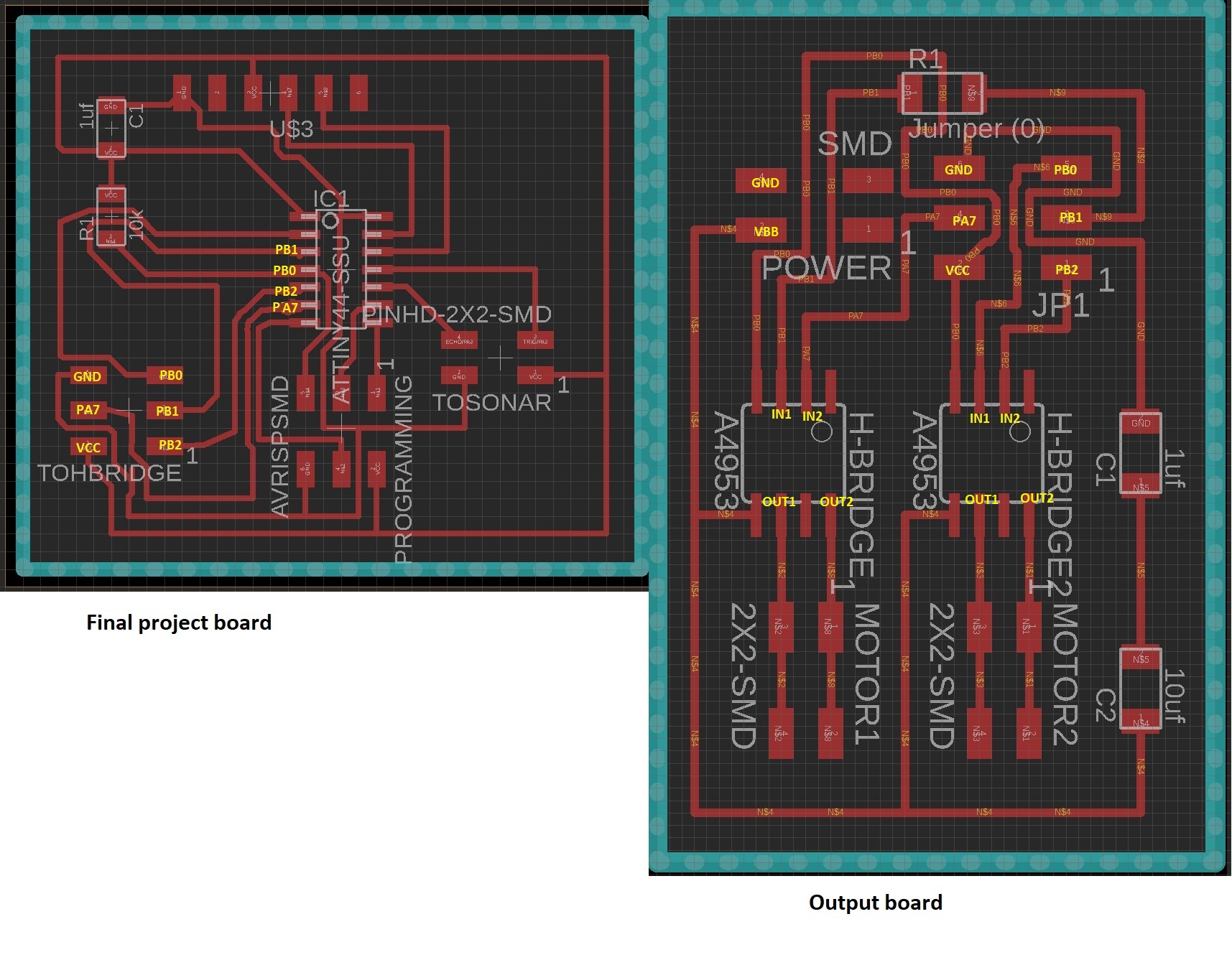
- I also made the corresponding changes to pins in neil's C code, and added the F_CPU to be 8 mhz as earlier in input week. I did no changes to the main code.

- After these changes in the code I selected build --> build solution, and
- build --> Compile solution. Both went through without problems
- Next I connected the FabIsp programmer to the computer and to my final project board
- Then I connected my final project board to the computer with the ftdi cable.
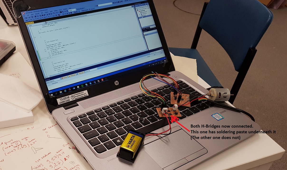
Below you can see my fancy setup. The main project board is on the keyboard there, the H-bridge board is on the lower left, almost making it to the picture, and also the sonar used on week 11 is seen dangling there.
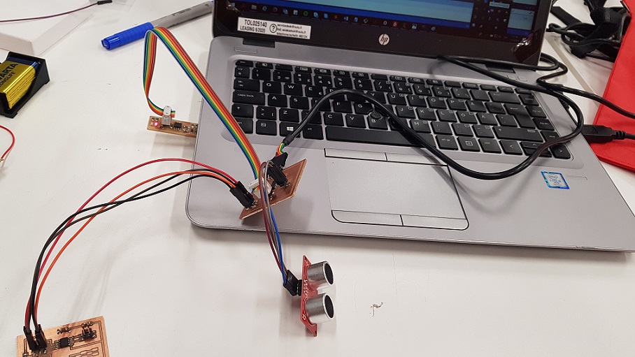
All was ready, I was excited. I selected build --> AVRDude, and everything again wen't through without a glitch.
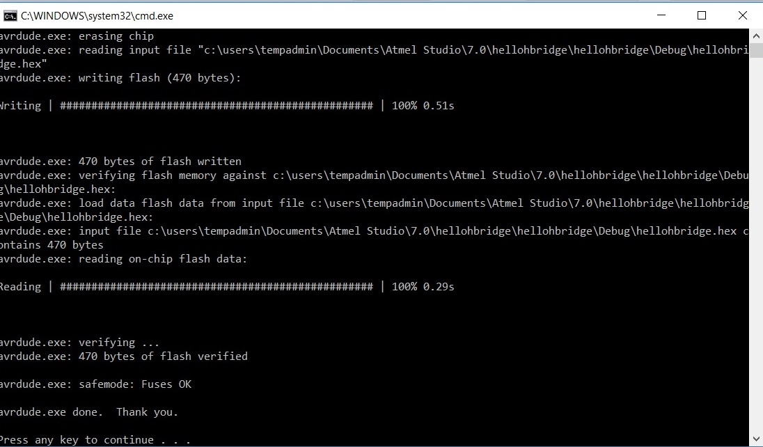
Here is my c code
- Slightly modified c code
Padding myself in the back here. A real electronics guru in the making, everything working like it should.
- I removed the fabISP from the computer and from the final project board
- Then I attached motor to the H-Bridge board
- And the 9v battery to power the motors.
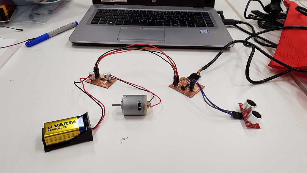
Didn't work.
A very anticlimatic end to a friday night I might say.
Troubleshooting
On friday I fiddled with the project for a while trying to troubleshoot. To help me was my fellwo FabAcademy student Ari. We noticed that:
- When the battery and motor are connected, nothing seems to be overheating
- The battery and the motor work - We got the motor running with the straight connection
- My final project board and FabISP still work, I reprogrammed the sonar code there, all good and working
This isolates the problem to
a) The H-Bridge board (is all soldering OK, the components working? Is the schema wrong?)
b) the connection I made between the two boards (which I doublechecked using my connections picture)
c) the connection between the board and the battery
d) the connection between the board and the motor, or
e) my changes in the code.
Next monday, with the help of my local instructor
- I simplified the code a bit, commenting out all of the other parts of the main loop, except "go forward fast"
- I tested both boards with a multimeter, "beebing" to make sure all of the pins from the final project board attach to the corresponding pins in the H-bridge board
- I checked for short circuits
- I tested both boards with an oscillator. It seems that the attiny is sending the signals, and they can be traced all the way to the H-Bridge input pins. The output part just does not seem to happen
- I checked the H-bridge input and output pin voltages with a multimeter (one side to ground, one side to pin you are measuring) :
-- In1: 0v
-- In2: 3.75v
-- Out2: 9.27v
-- Out1: 9,27v
-- VBB from the battery: 9v
-- Vref from the final project board:5v
--> Ivan advised me that one of the "outs" should be at 0, so there is atleast one problem. But why does this happen?
To troubleshoot further, I have checked some of previous years FabAcademy student files, Neil's board and in the datasheet
- Grace Copplestone W11: Here it says that the A4953 has a ground pad on the underside of the chip that needs to be soldered to the board.
-->This is something I had not noticed. I checked the datasheet of the A4953: "For optimum electrical and thermal performance, the A4952/A4953 must be soldered directly onto the board. On the underside of the A4952/A4953 package is an exposed pad, which provides a path for enhanced thermal dissipation. The thermal pad must be soldered directly to an exposed surface on the PCB in order to achieve optimal thermal conduction. Thermal vias are used to transfer heat to other layers of the PCB."
--> The local instructors believed that the H-bridge should work even without having the pad attached. Nonetheless, we tested this with the other H-Bridge (also the thermal pad) and the 2*2 pin header to my board (changed Neil's the code to fit the new pins), and connected the motor to the new H-Bridge. Did not work.
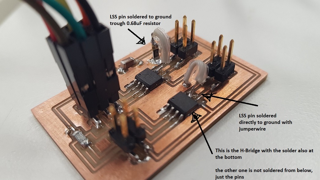
- Robert hart W11: "The motor driver chip, A4953 has a pin that I am not using. It is labelled LSS and provides current feedback. I did not connect it to anything on my board, and as a result the chip did not drive the motor. As soon as i connected it to ground, first through a 0.33 Ohm resistor (as on the datasheet) and then directly, the chip functioned."
- This is also something that was mentioned in the datasheet: "In order to use PWM current control, a low-value resistor is placed between the LSS pin and ground for current sensing purposes. To minimize ground-trace IR drops in sensing the output current level, the current sensing resistor should have an independent ground return to the star ground point."
--> We connected the LSS pins to ground while troubleshooting with Jari (not through a resistor though),this did not work
--> Next as advised by our lab leader Jani, I added the low value resistor to the LSS pin of the other H-Bridge. This still did not work
What I am thinking about now:
- In Neil's board, the LSS pin is connected to the ground pad underneath the H-Bridge. Is that the "star ground" that is discussed in the datasheet? He does not have a resistor there in the middle.
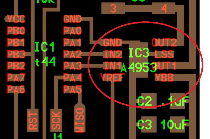
- From the datasheet: "The load supply pin, VBB, should be decoupled with an electrolytic capacitor (typically 100 μF) in parallel with a lower valued ceramic capacitor placed as close as practicable to the device."
- I also found something related to this from Randi Williams' documentation: "One important thing to not forget is to use capacitors on both H-bridges. I only used one set of capacitors, so this could be a reason why the electromagnets did not work"
--> I have 2 capacitors, so this should be OK, buuuut - I also have 2 Hbridges. Should I also have 2 more capacitors? If not, could the capacitor be too far from the H-Bridges?
--> I spoke to the lab leader Jani, who believes this should not be an issue. He did take a look at my documentation though, and said that one problem with the capacitors is that they are now in a series (sarjana) when they should be parallel (rinnakkain).
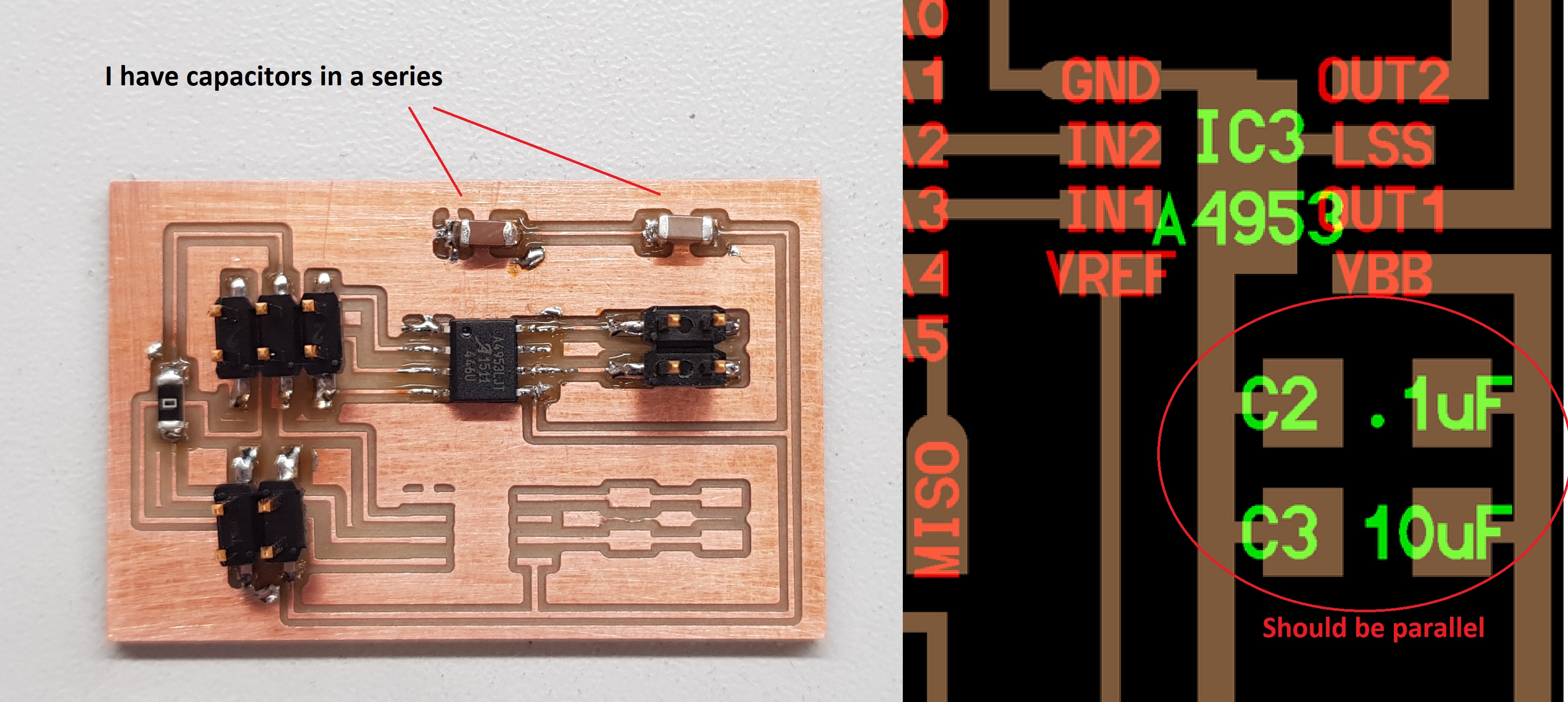
I therefore unsoldered one of the capacitors, connected one end to the pad, and one on the ground, and addded a jumper. The soldering job is crappy on the last jumper though. Didn't work.
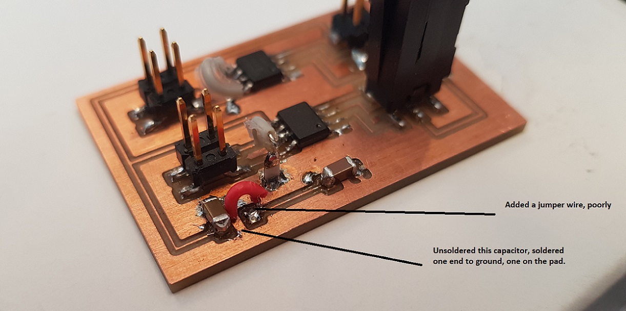
Hello H bridge
After spending more time than I would want on this, I finally decided to try and go back to the basics. I redraw Neil's Hello H-bridge board, thinking that if I could get this to work, I could then just start elaborating from that for the final project.
Here is the board and schema
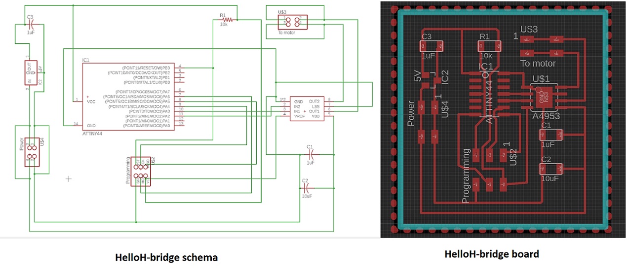
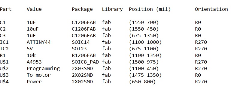
and the partlist
Here are my design files, and the traces and outline files
- H-Bridge board .sch schema file
- H-Bridge board.brd design file
- Traces .png file
- Outline .png file
And the milling files for roland mill prepared at fabmodules
- Traces .rml file
- Outline .rml file
aaaaaaand - After I redraw this, I of course got my original board to work. THis was ever milled of stuffed.
Below is how we pinpoited the flaw in my board.
My original design worked!
After I redrew the board, we checked it once more with Ivan, Jari and Antti from our lab helping me troubleshoot. We found two problems:
- I had named the pins that I used for the H-Bridge wrong in the pic that I had used when programming the attiny. I had named one one pin as PB0, when it was actually PB3. We saw this when we took a look at the ATTiny44 datasheet. It did not matter, as in the code, I had used the correct pins. I however uncommented the code back to the format that it came from Neil (so not just going forward).

- Then we checked how much power it takes to run the motor that I was using. It seems that the answer was more than it was getting. I connected my board to a another DC motor by Jameco, and it worked just fine.
I also tested the other H-bridge. It also works.
I fiddled with the Hbridge again a bit later. modified the code, adding the other H-bridge into the loop, as well as the sonar. All worked. Sonar was updating a little slow, but who cares, worked. Now i -just- have to come up with a way to make the motors react to data from the sonar.
Here is my code
- Both H-bridges and the sonar C code combined
Now I am of course thinking if I ever needed to do that resoldering of the components in the first place. Can't hurt I guess.
Some ideas:
- Maybe the 9v battery is not a good idea with the original dc motor, and instead I could use 2AA batteries.
- We thought about using two 90 RPM micro gearmotors instead of the stepper motor. We tested one with neil's code and it was running fine with the simple code (just forward), but when we uncommented rest of the functionality, the micro gearmotor did nothing. The local instructors troubleshooted that it might be about the code --> Something happens too fast for the motor to be able to react.
Problems had and lessons learned
- There were A LOT of problems this week. That actually in my case spanned over 3 weeks before I got one motor to work. I did read the H-bridge datasheet before starting, but when you don't speak fluent electronics, these things are not that easy to understand. And that is where I think a lot of my problems originate from: my lack of experience with electronics. But hey, with this many failures I am learning a lot. Next goal, world domination.
- I have documented my problems above in detail, here is a summary:
--> Drew the boards over and over, and still managed to name some pins wrong
--> Using a serial connection with my capacitors, when I should have used parallel
--> Not noticing I need to use connect LSS pin on h-bridge to ground (and then not noticing I need to add a small resistor between them)
--> Not noticing that the Hbridge bottom pad should be soldered to ground
--> Got two smaller motor to work with the Hbridges, the original does not work, there is not enough power.
Copyright © Heidi Hartikainen 2018
Template copyright ©Blackrock Digital LLC 2013-2018

This work is licensed under a Creative Commons Attribution-NonCommercial-ShareAlike 4.0 International License.