Designing the positive mold with Fusion 360
I decided to make a snowflake design for my mold this week. As my skills with Fusion 360 are quite limited, I figured this sort of a geometric shape would be easy to do, and I figured I could use the mold to make christmas ornaments or my own chocolates.
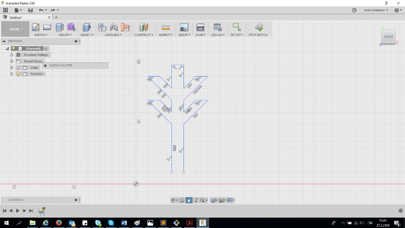
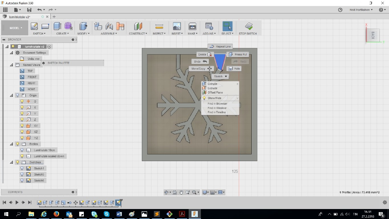
I started the sketch, and used the line tool to draw one branch for my snowflake
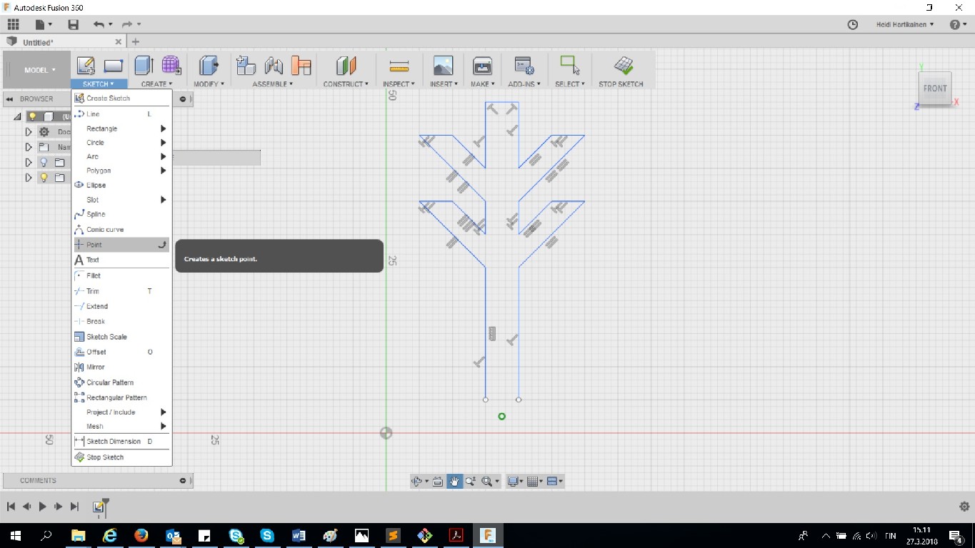
Then I created a point under the branch, and defined it to be a fixed center point.
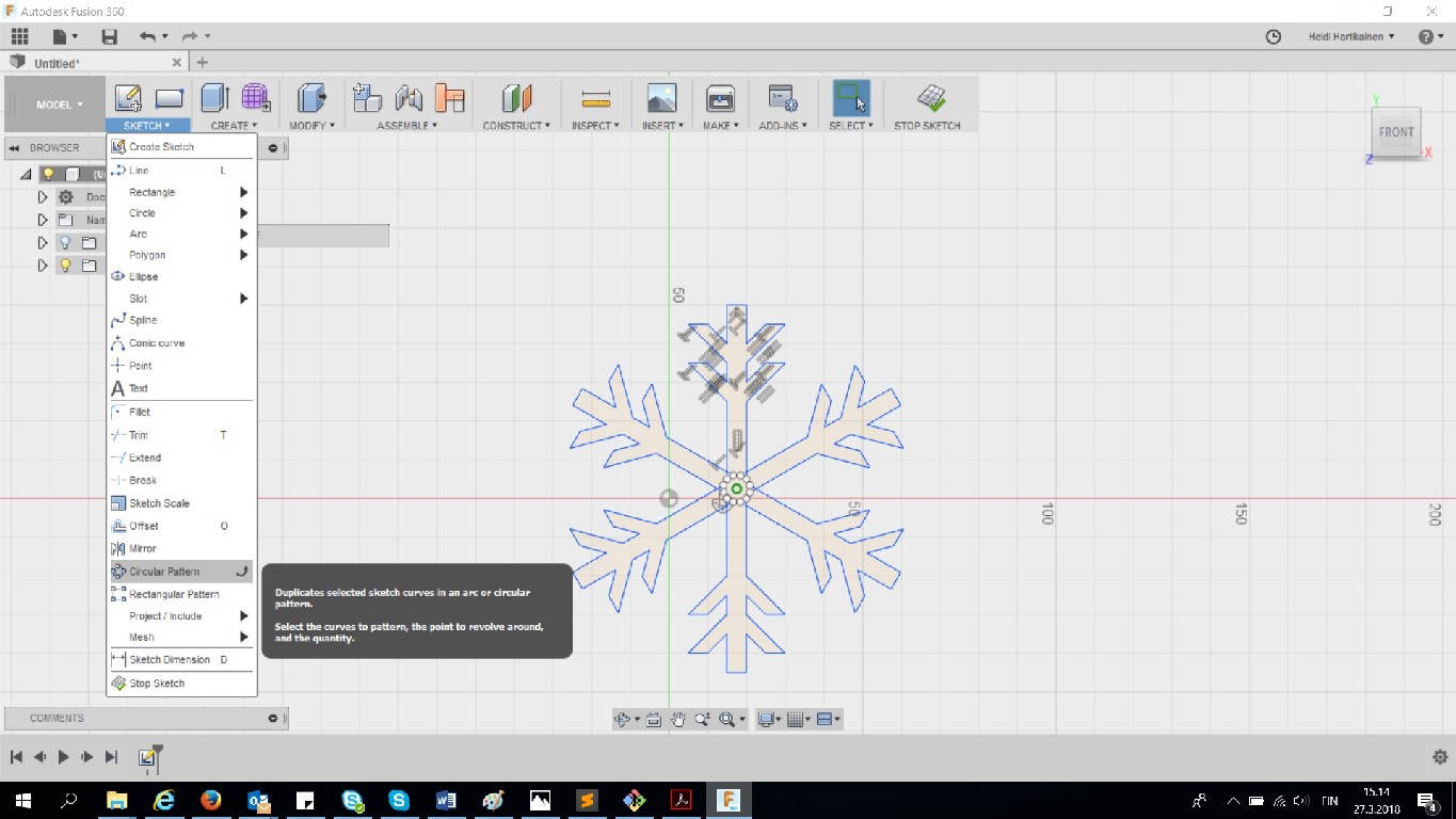
After that, I selected the snowflake branch I had just skeched, and selected to create a circular pattern around the fixed center point I had just created
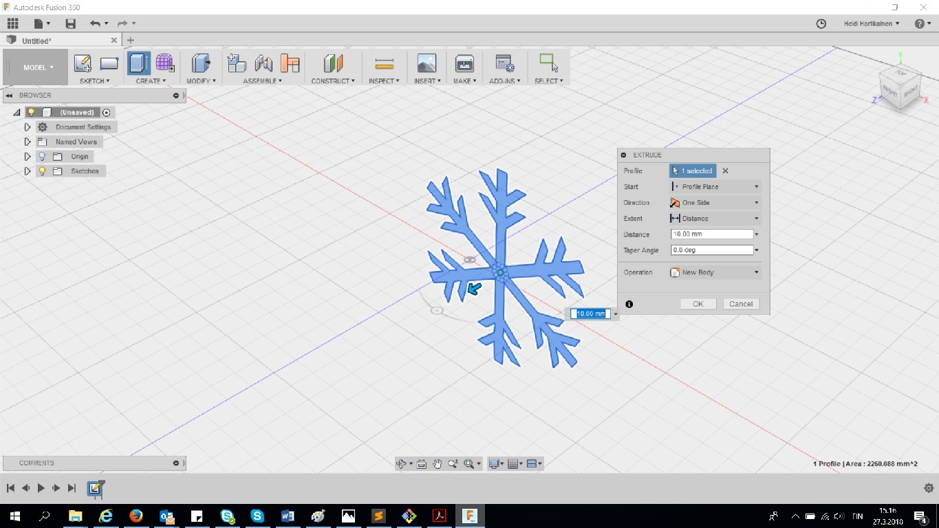
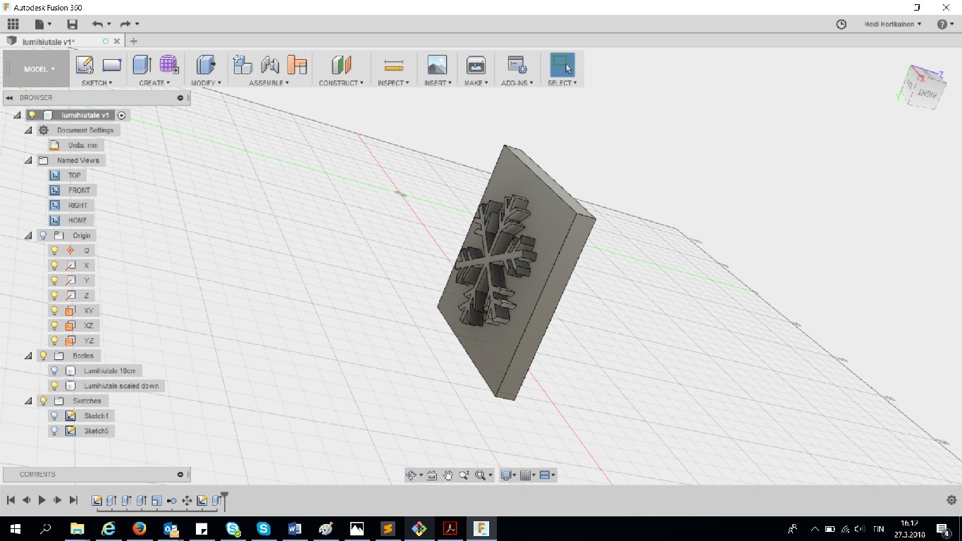
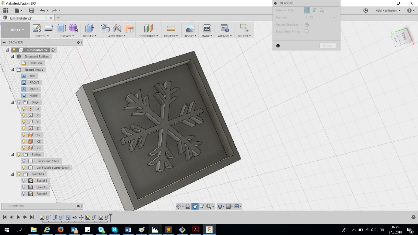
Next I selected create --> extrude, and made my snowflake 10mm deep
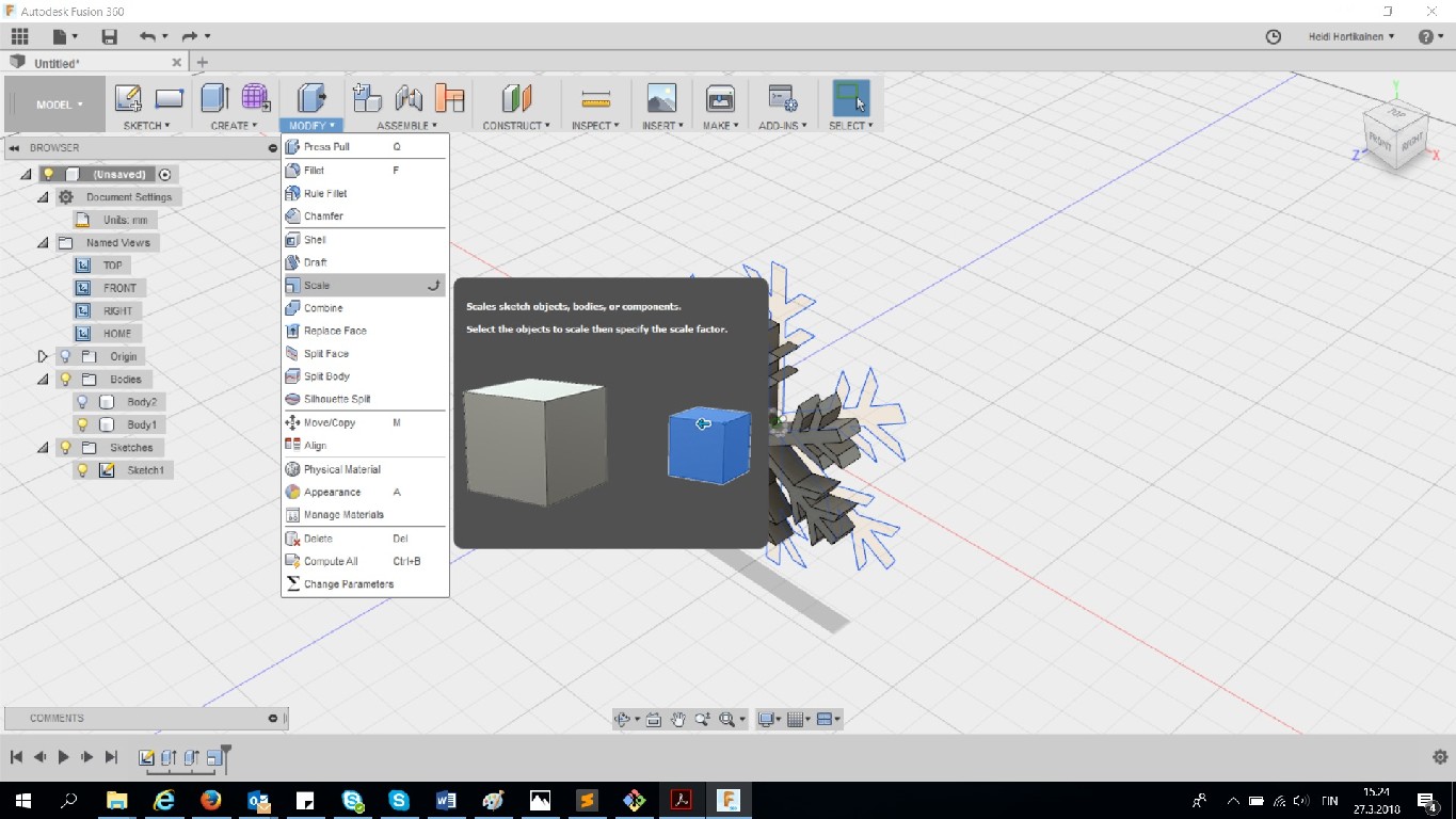
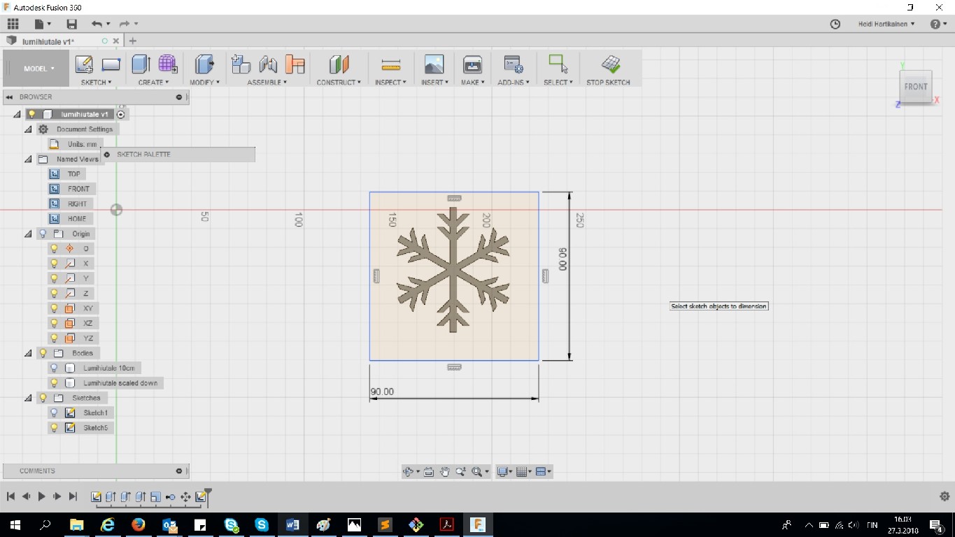
At this point, I noticed that my snowflake was quite big, over 10cm in diameter, so I decided to scale it down a bit --> I scaled it down to 7,5 cm.
After I scaled the snowflake down, I proceeded to create the box around the snowflake. I first selected the "backside" of the snowflake, and selected to create a new sketch on it. I created a two point rectangle
Then I again used create --> Extrude, and pulled the box to be 10mm deep
After that, I created the edges for the box. I selected the front side of box I had just created, and selected to create a new sketch on it. I created another two point rectangle inside the original one. The thickness of the walls is 2.94mm
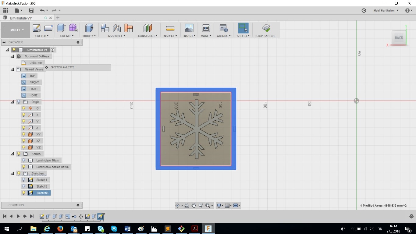
Then I again used create --> Extrude, and pulled the sides to be 10mm deep.
Next I created the hole for pouring in whatever material I would use to create snowflakes, as well as an airhole for air bubbles to escape
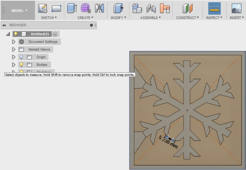
After that, the mold was pretty much finished. I still used the "inspect" tool from the menu to double check that the drilling bit will have anough space to move (for example between the branches). I was explained by the local instructor Ivan, that if the tool does not have enough space to move, depending on the software used to define toolpaths, the tool might remove more material than is planned, or it might not mill the paths which would not fit with the given mill size.
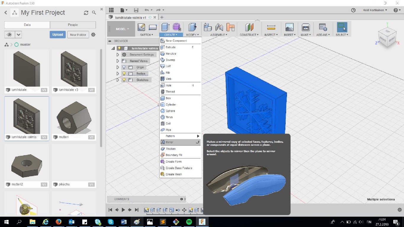
After all of that was checked, I used the mirror tool to create the mirroring part of my mold.
Here are my design files
- Fusion 360 editable (.f3d) file
- Side A of snowflake mold
- Side B of snowflake mold
Machining the positive mold
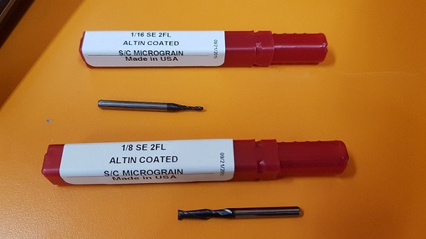
I took my design files out as .stl files, and headed towards the milling machine and the computer that it is controlled with. Here is the Roland Mill SRM-20 that is used in FabLab Oulu. I am using blue machining wax as material for the mold and 1/8'' flat milling bit (2 flutes) for roughing and 1/16' for finishing.

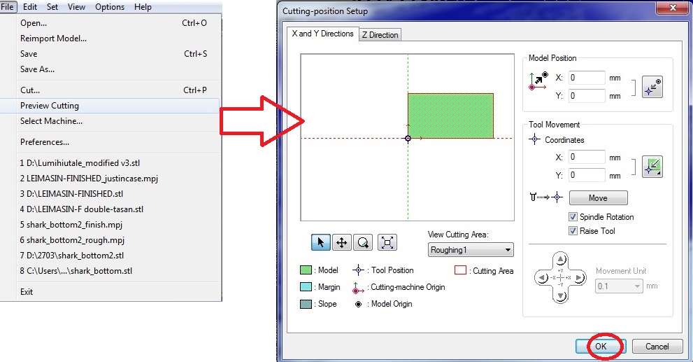
The program that is used to set up the cutting this is called MODEL A player. I opened the program, and then opened .stl file in it
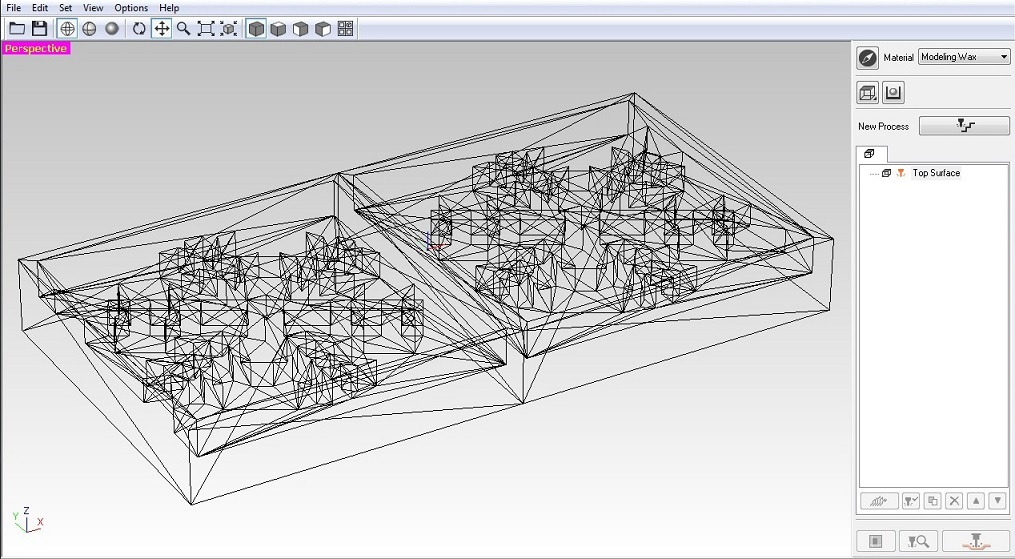
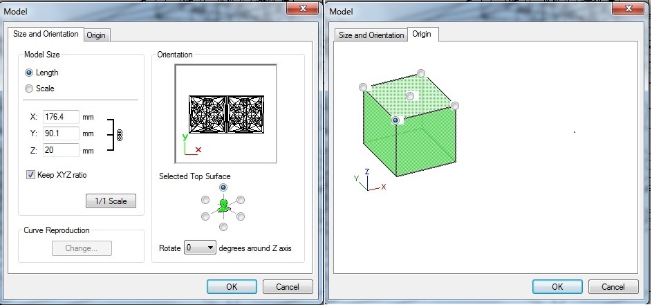
The first thing I did, was to use "set"-->"model" options from the menu above to set the size and orientation, as well as the origin point of the milling. The size and orientation came from the design file and I did not change them, as for the origin point, I selected the lower left corner, on the surface of the material
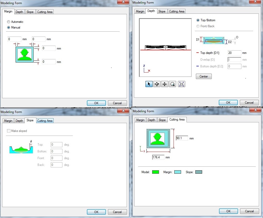
Next I selected use "set"-->"modeling form" options from the menu above.
I specified the marging to be 0, but left the other settings untouched
Next it was time to create processes for roughing and finishing
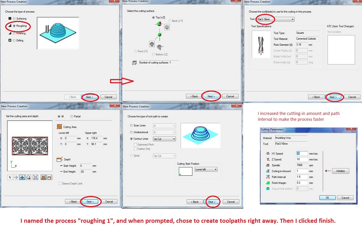
First I selected "set" --> "New process" to create the roughing process and define parameters for it.
- I selected the process to be roughing
- The cutting surface is the top by default
- I selected to use the 3.18mm flat tool for this process. The tool (Flat3.18mm (1/8''), was already created by Fab Lab staff.
- The cutting area is basically the size of your design
- "contour lines" and for the machine to cut upwards are a default setting here
- In the cutting parameters tab
--> The X/Y speed is 30mm/sec. I think that this was the default for roughing. I was explained by our local instructor Ivan that the XY speed depends on the milling bit used as well as on the material to mill.
--> the Z speeds is 10mm/sec
--> Spindle is 7000rpm
--> The cutting in amount (how deep the milling bit goes on each path) is 1. This was increased from the default to make the process go faster. This means that the machine will cut more material. This makes the end result will be a bit rougher, but the finishing process should take care of that.
--> Path interval (How much space there is between paths) was set to 1.5 to make the process faster. This means that the tool parth will be further away from each other and this makes the end result will be a bit rougher, but the finishing process should take care of that.
--> Finish margin is 0.2mm
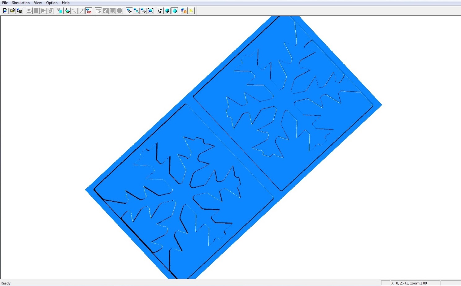
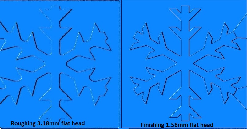
Once I was done setting up roughing, I selected to preview cutting to see how it would look with my settings, and how long it would take.
As you can see, a lot of the details of the snowflake are lost in the roughing process. The larger milling bit would round up some of the sharp 45 degree angles I had, because it had no room to fit in them. However, I was told not to worry about this - We could change the milling bit for a smaller one in the finishing process which would bring out the detail.
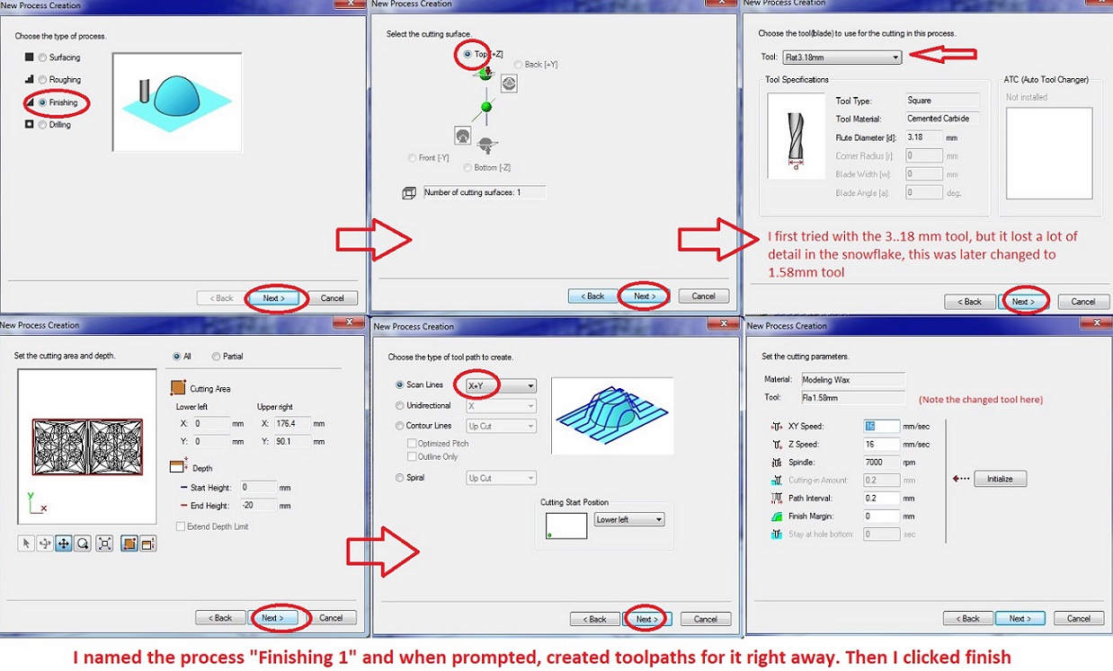
Next I selected "set" --> "New process" to create the finishing process and define parameters for it.
- I selected the process to be finishing
- The cutting surface is the top by default
- I selected to use the 1.58mm flat tool for this process, as it would allow me to keep more detail in the snowflake as the bigger tool. The tool (Flat1.58(1/16') was already created by Fab Lab staff.
- The cutting area again is the size of your design, walls and all
- I chose the "scan lines X+Y" as toolpath type instead of the default (just X) as I heard that it will produce a nice finish (cleans the surface from both x and y directions)
- In the cutting parameters tab
--> The X/Y speed is 16mm/sec
--> the Z speeds is 16mm/sec
--> Spindle is 7000rpm
--> Path interval is 0.2mm (I might have lowered the path interval from 0.3 to 0.2mm - I am not completely sure). As you can see, in the finishing the path interval is much smaller than in the roughing.
--> Finish margin is 0mm
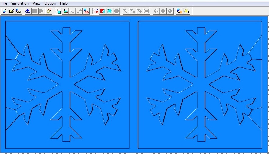
Once I was done setting up finishing, I selected to preview cutting to see how it would look with my settings, and how long it would take. As you can see, the smaller milling bit brought a lot more detail out of the snowflake.
Now all that I had to do, was to click "File" --> "Cut" to send the job to the roland mill.
The Roland mill needs some setting up as well before you actually start cutting.
- First a block of blue machinable modelling wax is attached to the milling machine with double sided tape. This is where the mold will be milled.
- Next, an allen key is used to remove the milling bit inside the machine, and to secure the milling bit used. I had to change the milling bit once: I used the larger milling bit in the front for roughing, and then changed to the smaller milling bit for finishing
After the modelling wax and the correct milling bit were in place, I open up the control panel program of the roland Mill and set up the X/Y/Z parameters.
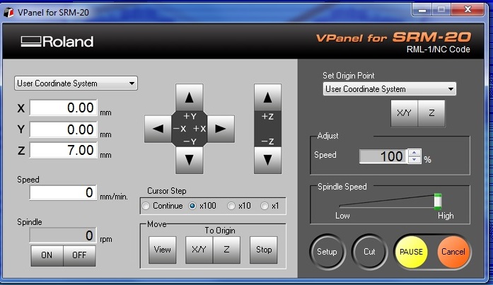
I first used the X/Y buttons to move the milling bit as close to the front left corner as possible and pressed Set Origin point --> X/Y.
Then I used the Z button to lower the milling bit as close to the wax block as possible. Before it touched the surface, I loosened it a bit with the allen key (so as not to drive it into the block), and lowered it manually. Then I pressed Set origin point --> Z. After that, I raised the milling bit a away from the surface, and pressed cut.
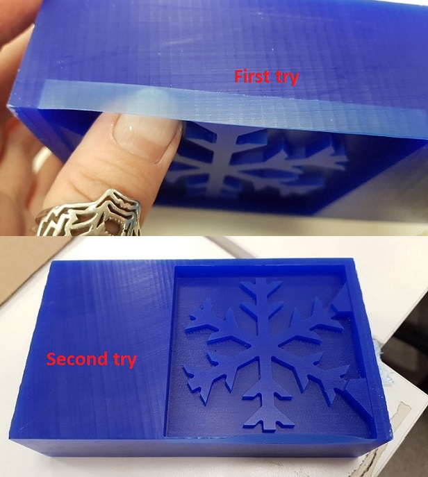
Here is the roughing being done, and the result of the roughing.
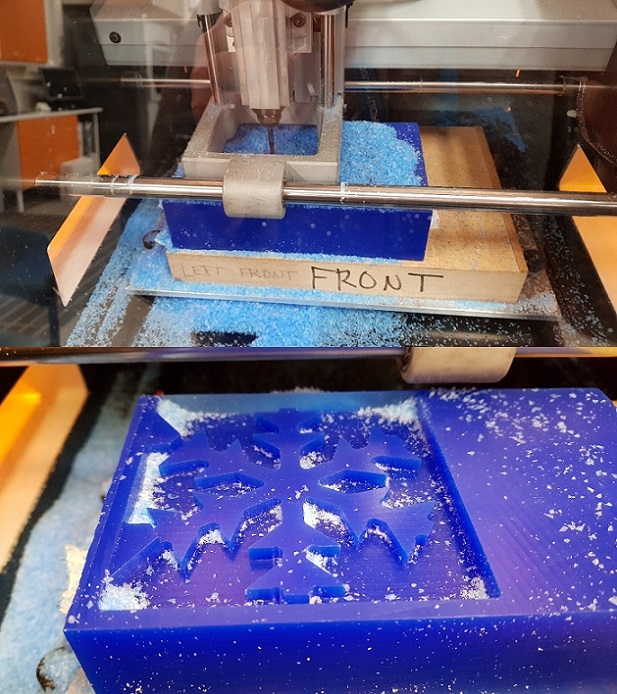
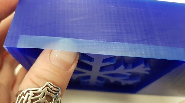
As you can see, the back wall of the mold was super thin, so I had to enforce it.
When milling the other side of the mold, I set the X/Y coordinates of the mill further front, and this did not happen again.
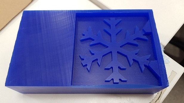
Here is the final result, after the finishing process. The roughing and the finishing combined took about 90 minutes.
Casting the mold
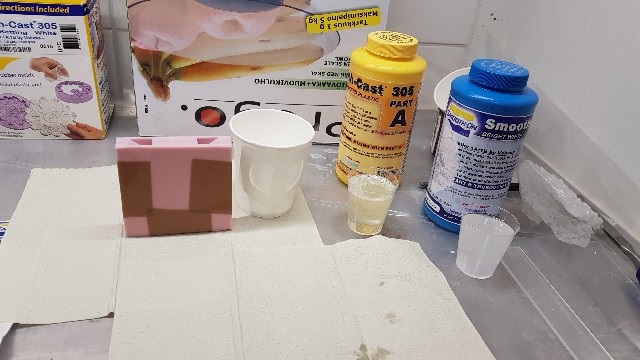
I selected to use the same rubber for making our my molds that we used in groupwork: SmoothSil 940, so I knew how to prepare it. I went to a properly ventilated room and started preparing it by mixing part A with part B. The mixing ratio is 100A:10B by weight. When Smoothsil 940 is mixed, it has a pot life of 30 minutes (pot life meaning that you have to use it within that time frame). The cure time is 24 hours – meaning that your mold is ready to be used in 24 hours after it is cast.
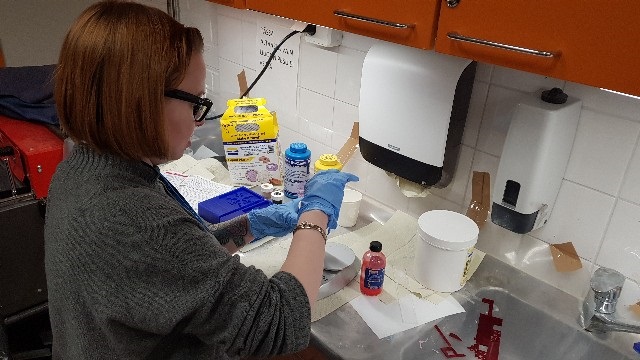
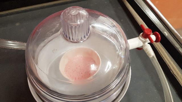
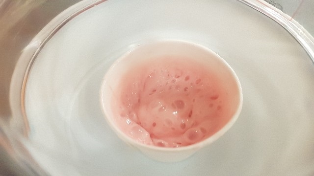
Before measuring the ingredients, I shook part B (red liquid) througly, as advised in the instructions. This was done to re-disperse the pigments that might have settled in the bottom of the bottle. Then I used a digital scale to measure the ingredients individually. As my mold was quite large I used 80 grams of part A and 8 grams of part B. Then I mixed them together a total of 3 minutes, scraping from the sides and the bottom several times. When I was done mixing the ingredients, I placed the pot in a vacuum for degassing. The instructions said the mixture should be in the vacuum for 2-3 minutes. I however held the mixture in the vacuum overtime, closer to 5 minutes, as new bubbles seemed to form all the time. At this point the product also expanded a lot in the pot, so it was good that I left quite a lot of room in it
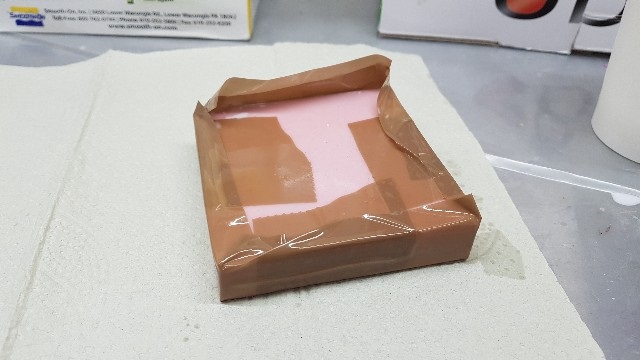
After vacuum, I poured the rubber into the mold on it’s deepest point, letting it seek its own way up and over the model. Here I noticed that there was only enough rubber to fill one mold, so I had to mix another batch, put it in the vacuum, and pour it. The consistensy of the two batches was a little different, with the second batch one having more bubbles. This is perhaps because I didn't let it to be in the vacuum for as long as the first batch.
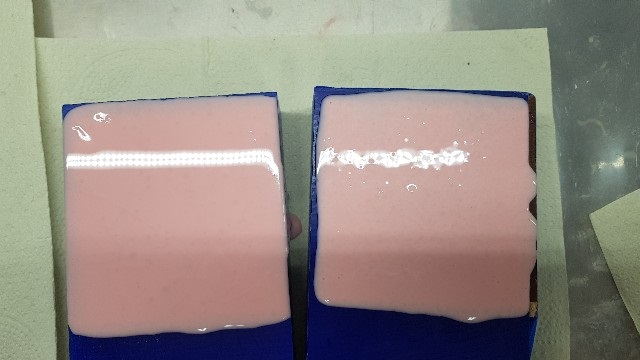
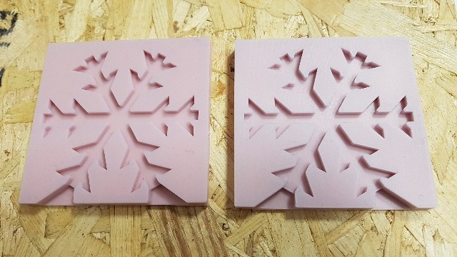
Here is how they turned out
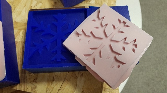
After removing the finished molds, I just cut out the leftover rubber on the sides with the scissors
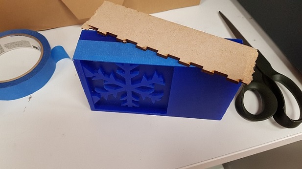
Using the mold
I used the mold two times with Smoothcast 305. I taped my mold to hold the two sides together so that I could pour the liquid plastic could be poured in. Smoothcast 305 has a potlife of 7 minutes and cure time of 30 minutes so you have to be quick to fill your mold. I shook the bottles containing Part A and Part B thoroughly, and dispensed equal amounts of both into measuring cups (4mils), then I mixed them together in a pot, making sure to scrape the bottom and the sides of the pot several times
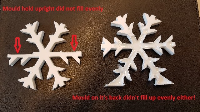
With the mold upright, I then poured the liquid into it slowly, and left the filled mold to cure for about an hour.
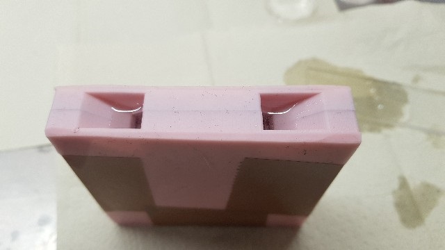
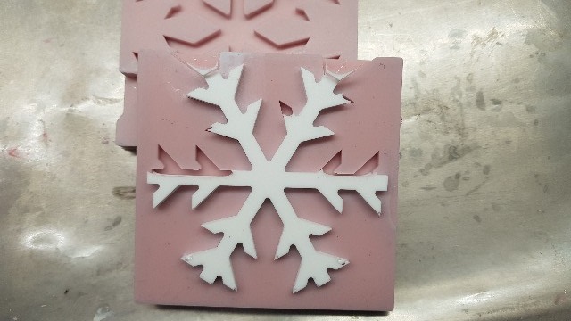
This was the finished result, as you can see, the mold did not fill up evenly on the sides, instead some air got trapped in the side braches.
I decided to try again, this time placing the filled mold on it's back, to see if it would fill up more evenly this way. As the airholes were on the top of the mold, I had to tape them shut to make sure the plastic does not pour out of them
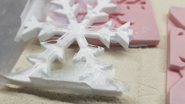
On the "backside" that was facing the table, the snowflake looks good!
The other side, on the other hand, was a whole different story. As the mold was filled standing up, some air was again trapped in the side branches and when I laid the mold on it's back, it just rose to the top of the design.
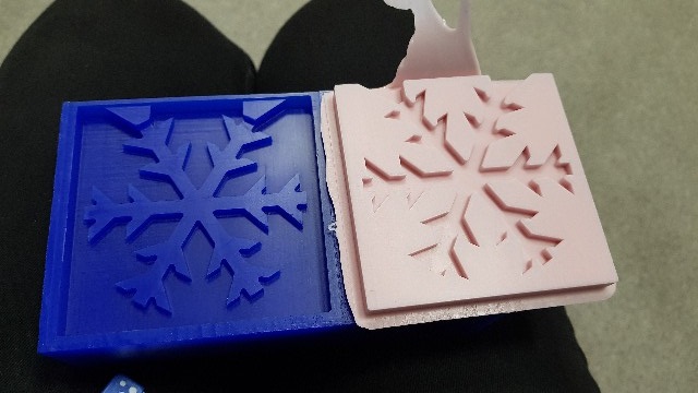
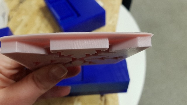
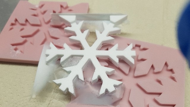
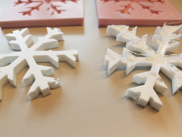
Here are the two snowflakes side by side
Problems had and lessons learned
Designing and Milling
- When I exported my positive mold to the Roland mill and simulated the milling with MODEL A player, I saw that a lot of details were lost of the snowflake design with the 3.18 milling bit we were supposed to use. It roulded up a lot of 45 degree angles that were geometric in the design because it was quite large and round in shape --> I had to change to a smaller milling bit for the finishing process so that the mold would turn out half decent / not too much detail would be lost. Perhaps the mold could be improved by making the angles less sharp, or by incorporating a more rounded in the first place
- However, my original design was too deep to mill out with the smaller milling bit and I had to modify the design. As my Fusion 360 skills are limited, I did not know how to slope the edges of the mold to account for the smaller mill bit --> so I just lowered the edges and the snowflake design. This caused the mold to be very shallow in some places (only a couple of mm), but not problematically so
- In my original design where the molds were side by side. However, this design was too large to be milled on to the wax block provided. I had to divide it into two parts.
- Even after dividing the molds into two, the design was still quite large. On the first mold I milled one of the edges very very thin and I had to reinforce them. --> When milling the next side, I made sure that the origo was set as close to the front left corner of the wax block as possible and it turned out better
Using the mold
- The snowflake design was very tricky to try and fill up with plastic. First I cast the parts with the mold standing up, and the plastic I used to cast my parts did not rise evenly in the branches of the snowflake --> The braches were quite thin, and when they filled up from the center, instead of rising up and filling the smaller parts of the snowflake side branches the plastic just rose up in the mold. Result, there was a lot of air left inside on the sides. I then tried to lay the mold on it's back and the result was not much better. --> the problem now was that I still had to fill the mold standing up, and there was not enough material even when I laid it on its back. Perhaps the problem of air getting trapped in the braches could be fixed by adding airholes
--> Somewhere in there I had the inevitable "doh" moment when I realized that there was really no need for me to do a two sided mold. The snowflake was symmetrical and I could have just made it a bit deeper to make nice snowflakes while laying just one side of the mold in it's back.
- Just a note: I also milled out 3D molds for my a composite later on in FabAcademy with a CNC machine, during wildcard week. I think that the work done in molding an casting week really gave a good basis for this.
Copyright © Heidi Hartikainen 2018
Template copyright ©Blackrock Digital LLC 2013-2018

This work is licensed under a Creative Commons Attribution-NonCommercial-ShareAlike 4.0 International License.