- Assignment 12
Interface and Application Programming
This week I wrote several lines of code to interface my output board output board with my PC using Processing. With these tools I created a keyboard that generates on my PC the seven notes and controls the shape and amplitude of the waves.
Processing
Processing is an open-source computer programming language and integrated development environment (IDE) built for the context of the visual arts. I used it to make a small synth with GUI and serial controllable.
Requirements
To design the GUI I used the library ControlP5 2.2.6, while for the generation of the sound I have used the library Minim 2.2.2.
To install them I looked in the Contribution Manager by going to Tools -> Add Tool... and then to the section Libraries.
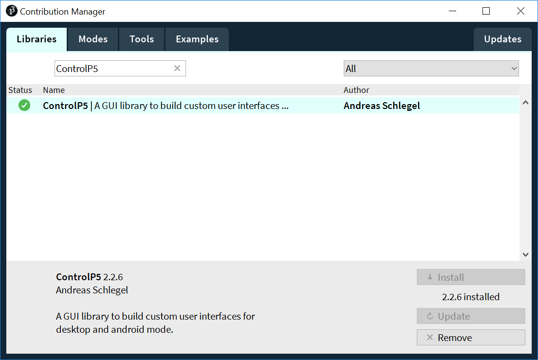
Figure 1. ControlP5
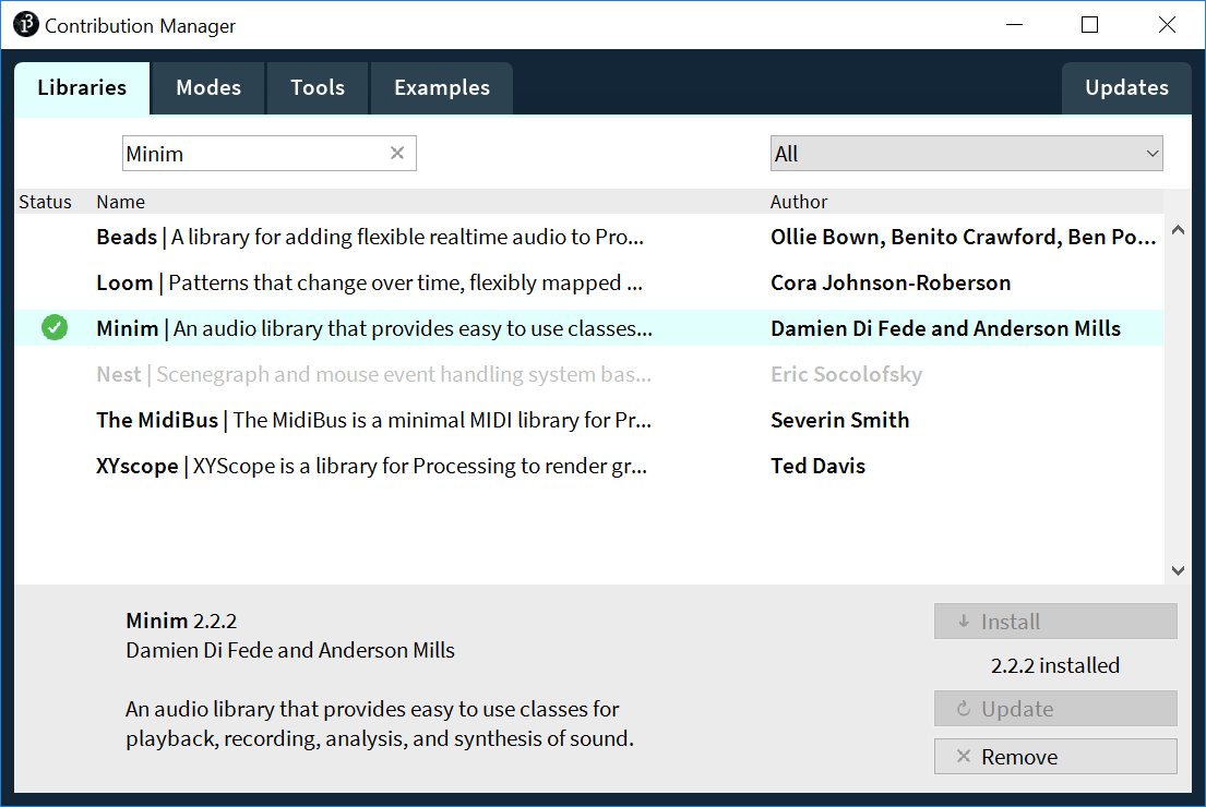
Figure 2. Minim
Sketch
Processing sketches, like Arduino's, need two functions: setup() and draw() (which
replaces Arduino's loop()).
In setup(), after defining the size of the window, I initialized 7 wave functions (one for each
note), 7 keys to play them and two knobs to control amplitude and waveform. Finally, if present, it connects
to the first serial port that it finds.
In the draw() there is only the background definition but it never changes.
Afterwards I declared some functions that are called by
callbacks when certain events
happen, in particular when the knobs are turned (knobX()), the keys are pressed
(controlEvent()) or a message arrives from the serial port (serialEvent()).
These in turn recall the functions to play the notes and change their amplitude and waveform.
In case the data comes from the serial port (in this case from an Arduino UNO) to execute
the corresponding command they must have the following format:
noteON n: start playing note n ( 0 to 7 )noteOFF n: stop playing note n ( 0 to 7 )setAmp value: set amplitude to value ( 0 to 1023 )setWf value: set waveform to equivalent value ( 0 to 4 )
Arduino
To control the PC by serial I loaded on my output board a sketch written by myself and to which I connected the various inputs.
Circuit
To make the circuit to connect to output board I used a breadboard, 7 momentary buttons and 2 potentiometers. I inserted 7 buttons with the GND in common with each other and the other contact with the output board pins, one each from pin 3 to 9. Instead, for the potentiometers I connected the side pins to the GND and VCC, while the center contact respectively to pins A4 for the amplitude and to pin A5 for the waveform.
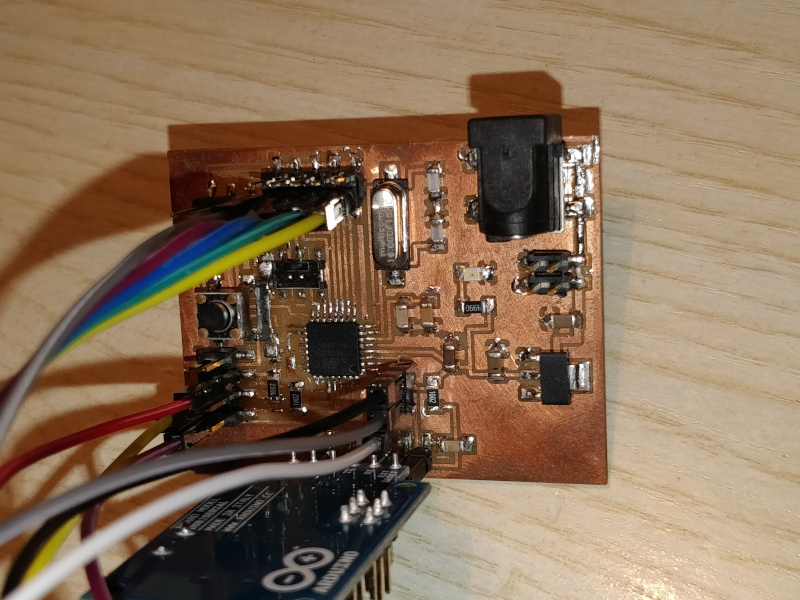
Figure 3. Connection on output board
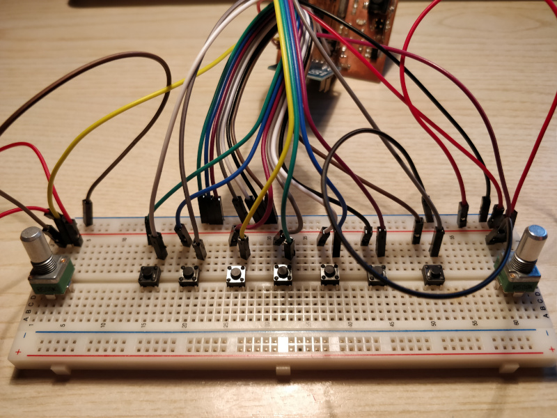
Figure 4. Connection on breadboard
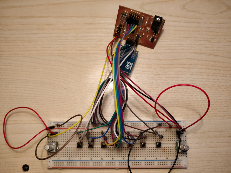
Figure 5. The complete circuit
Sketch
The Arduino sketch does not use any particular library.
In the setup it initializes the Serial to the baudrate of 9600 like the Processing sketch does and
initializes the digital pins as input by also activating the internal pull-up, this allowed me to avoid the
resistors in the circuit.
In the loop it reads the seven buttons and the two potentiometers, if any value has changed with respect to
the previous cycle, it sends the information of the new current state using the same format set
in Processing. The value read by the waveform potentiometer is first mapped from 0 to 4
before being checked and sent.
Result
To use the previous steps, first connect the output board to your PC and then click on Run to start the Processing sketch. Now by pressing on a button on the breadboard the PC plays the corresponding note and by rotating the potentiometers I can adjust the amplitude and shape of the wave. It is also possible to play from the PC by clicking on the respective virtual buttons and modifying the values of the potentiometers.
Unfortunately the amplitude reading does not have a stable value so the microcontroller continues to update the value even with very small variations making it useless to control it directly from the PC.
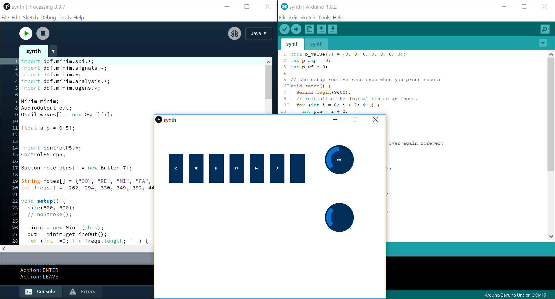
Figure 6. A screenshot of my PC during sketch running