- Assignment 09
Molding and Casting
To learn the technique of molding and casting I made simple stackable checkers.
Design
I used Fusion 360 to make the drawing as it already has CAM functions integrated. The shape of the checkers is very simple and easy to realize as rotational solid.
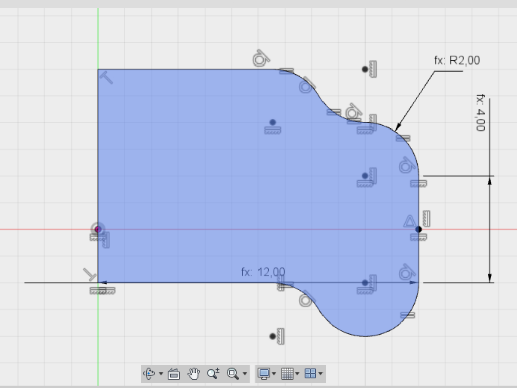
Figure 1. Section
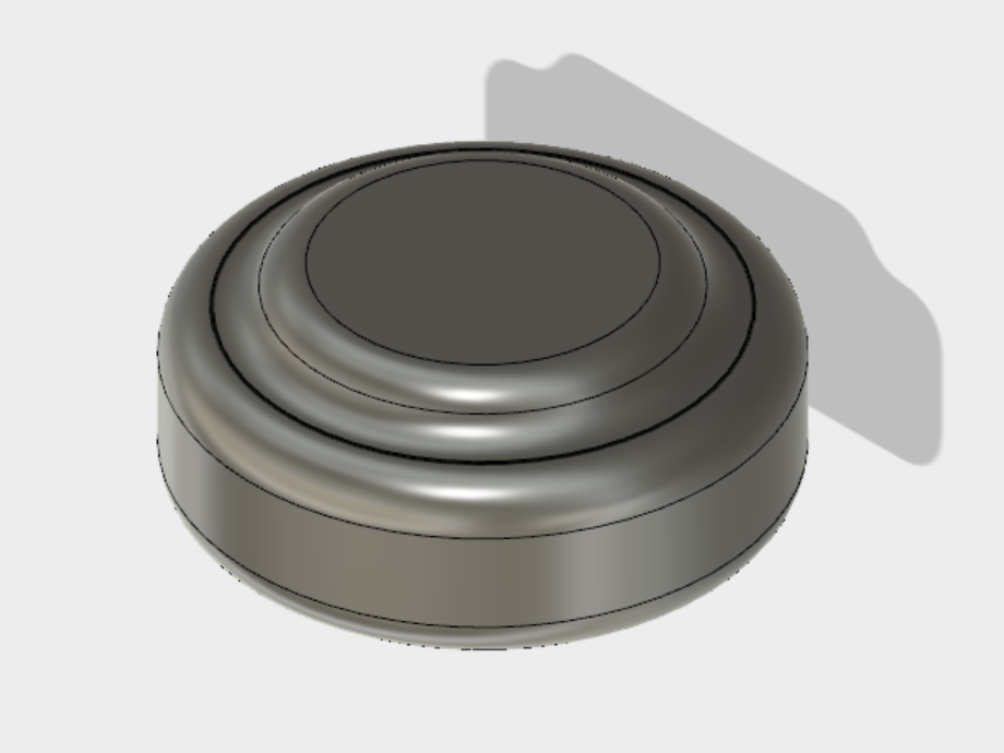
Figure 2. Checker
After I cloned it with a rectangular pattern and added the joints and a mouth. Finally I added the walls and the centrelines, this for both halves.
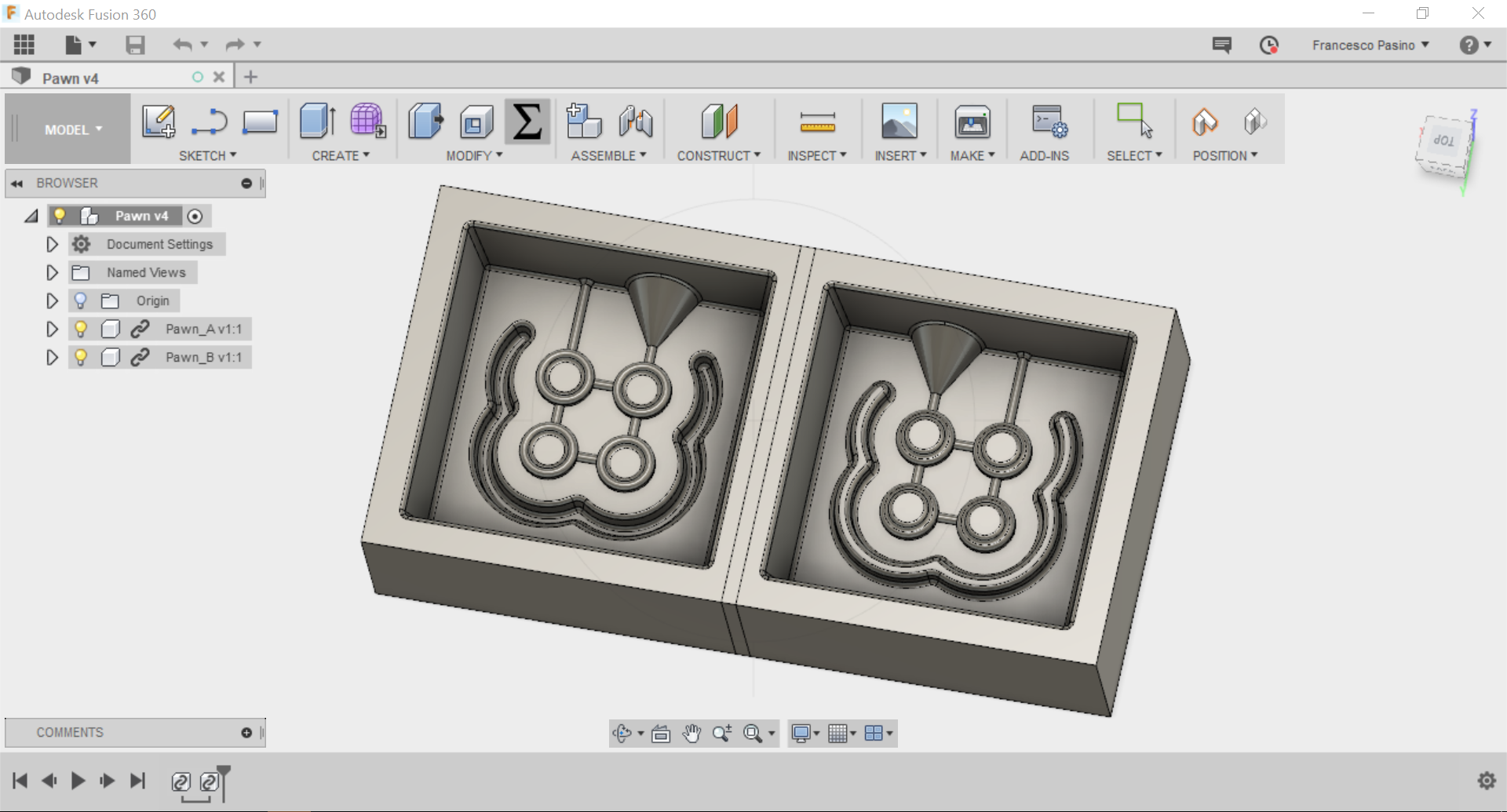
Figure 3. Masters
Toolpath
To mill the master I chose to use two tools, a ball end mill and a flat end mill.
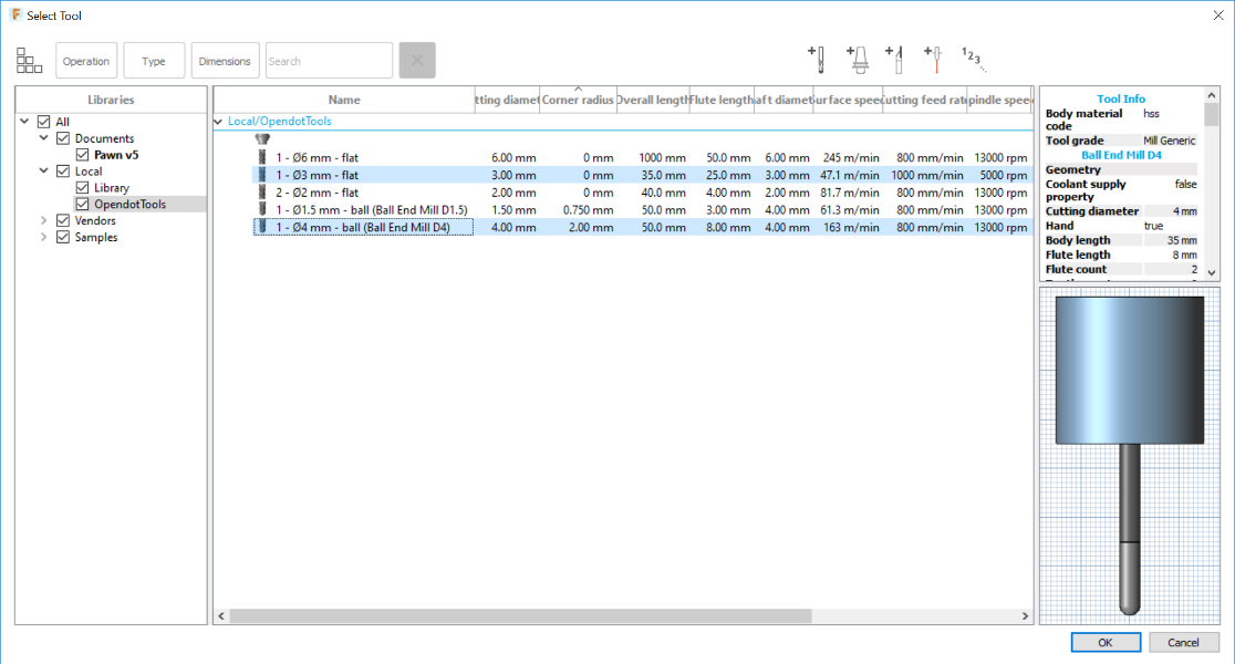
Figure 4. Library tools
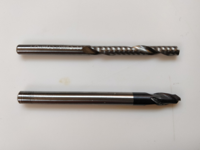
Figure 5. Tools
Ball end mill
With the Ball end mill I have created two toolpaths, one for roughing and one for surface finishing.
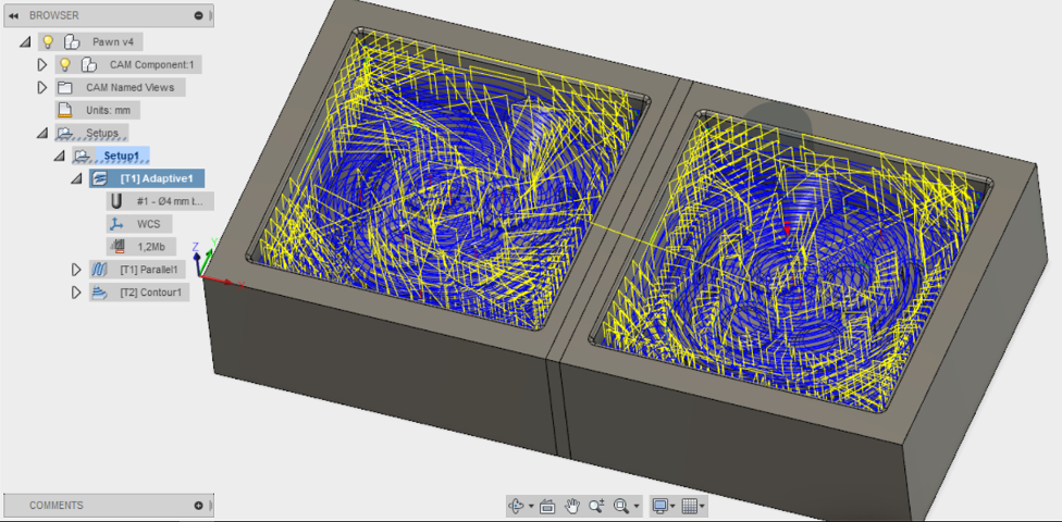
Figure 6. Roughing
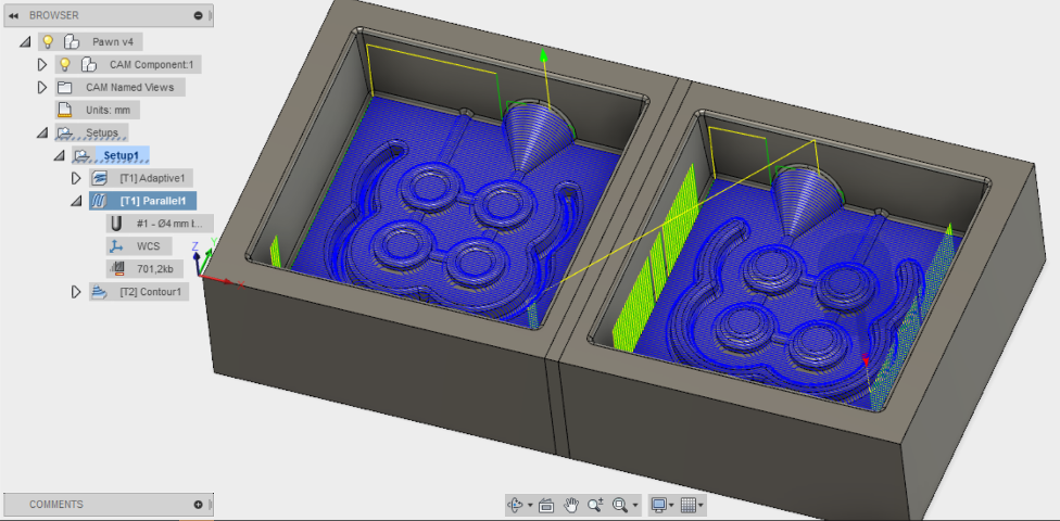
Figure 7. Finishing
Flat end mill
With the flat tip I have reworked all contours on the contact surface.
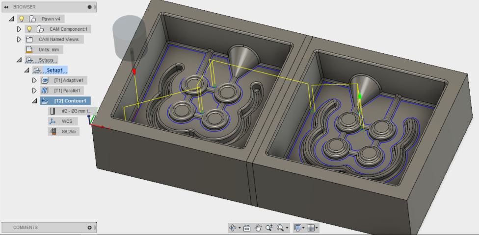
Figure 8. Contour
Export
To export the toolpath I used the Post Process feature and selected Roland ISO as Post Configuration. This I did separately for both tools so I have two files, one each.
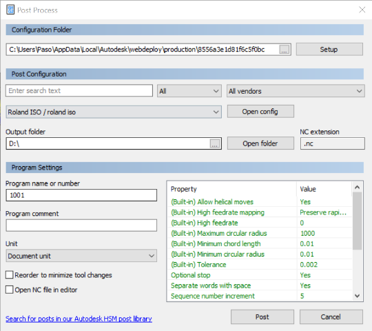
Figure 9. Post Process
Master
I chose polyurethane foam to make the master because it is very easy to mill and even in case of accidental collisions I would minimize damage. So I took a sufficiently large piece and with some double-sided adhesive I glued it to a wooden panel that I then fixed to the table with some office clips.
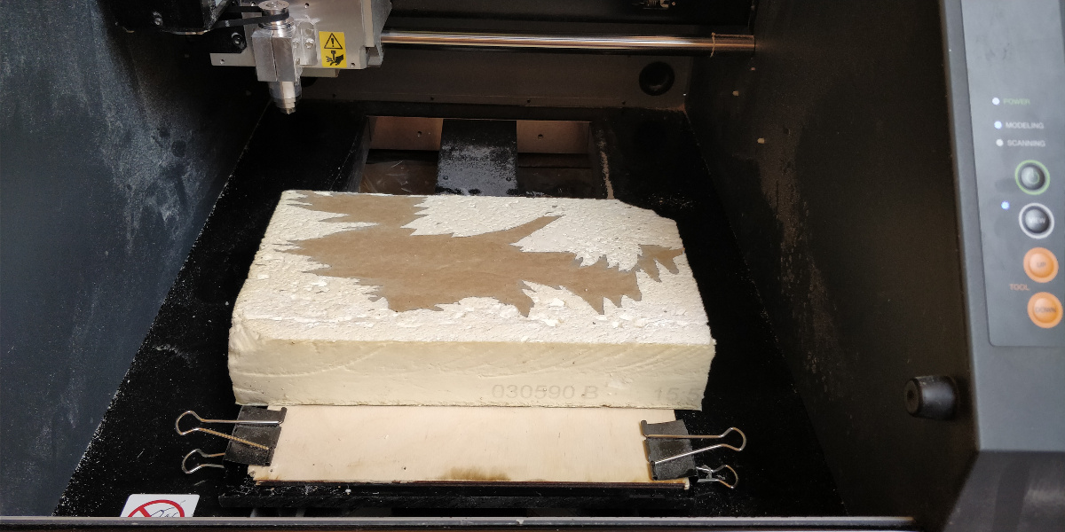
Figure 10. The raw piece
Ball end mill
Before starting the roughing procedure I reset the User Coordinate Systems to zero at a stable location using the method for electronic production. This will be used for tool change.
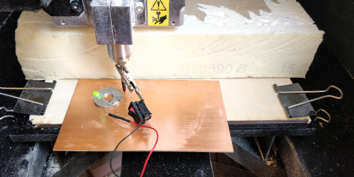
Figure 11. Z settings on machine for tool change
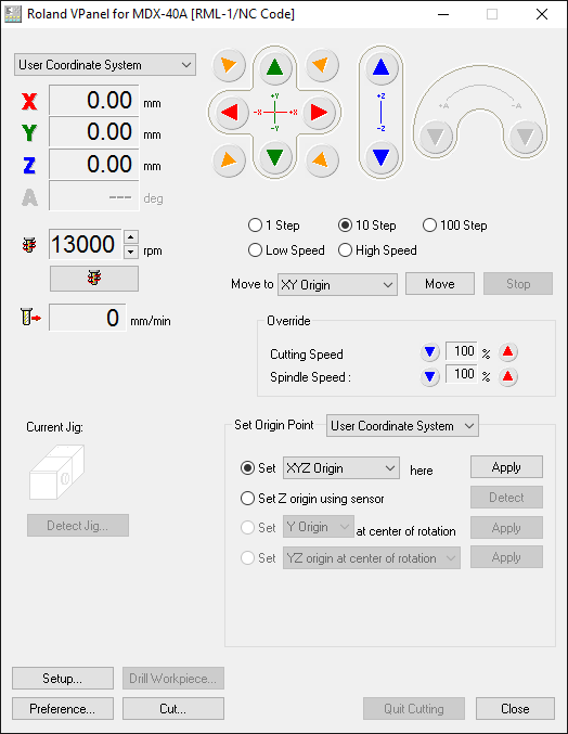
Figure 12. Z settings on PC for tool change
Therefore I placed the tip in the lower left corner of the top surface of the workpiece and reset the G54 coordinate system to zero. I chose that coordinate system because it is the one used by the gcode generated from the previous step.
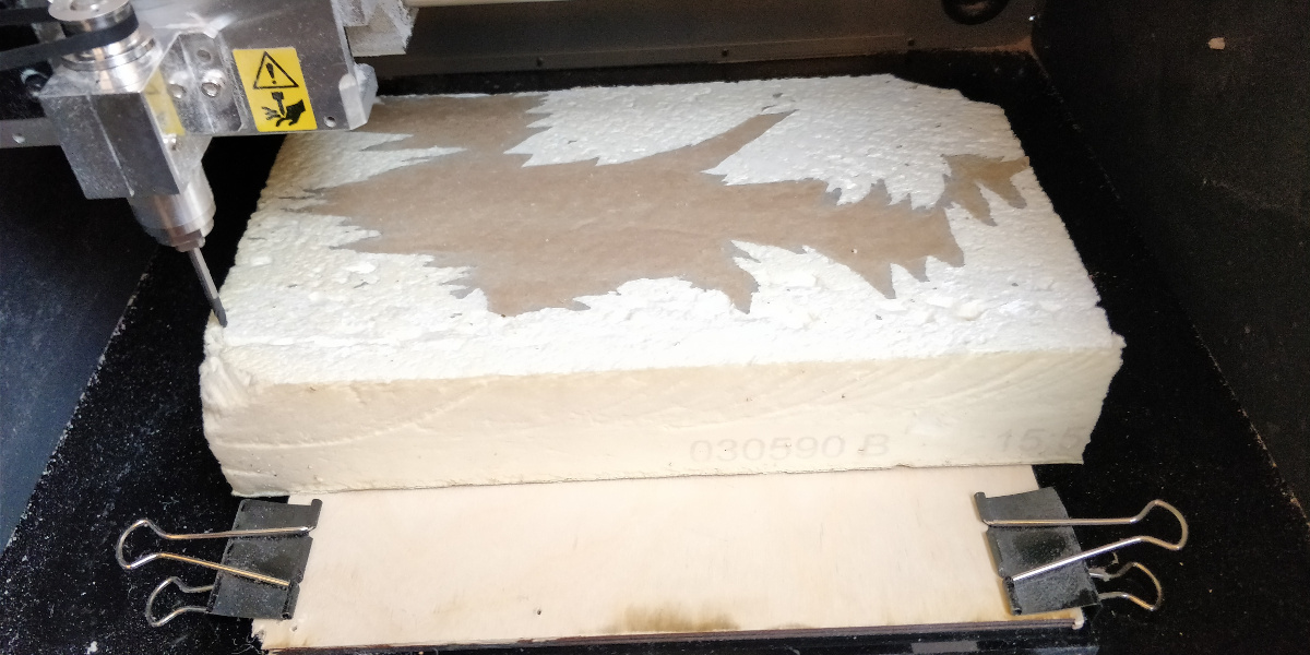
Figure 13. Z settings on machine to mill
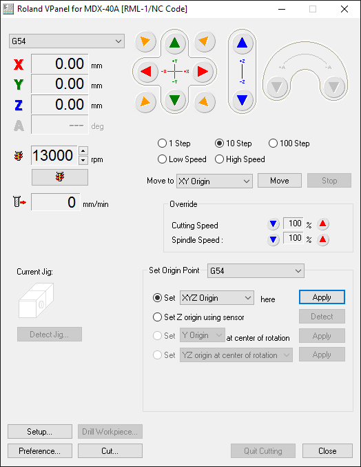
Figure 14. Z settings on PC to mill
Here are some photos during the milling process (after pausing and aspirating the already milled foam).
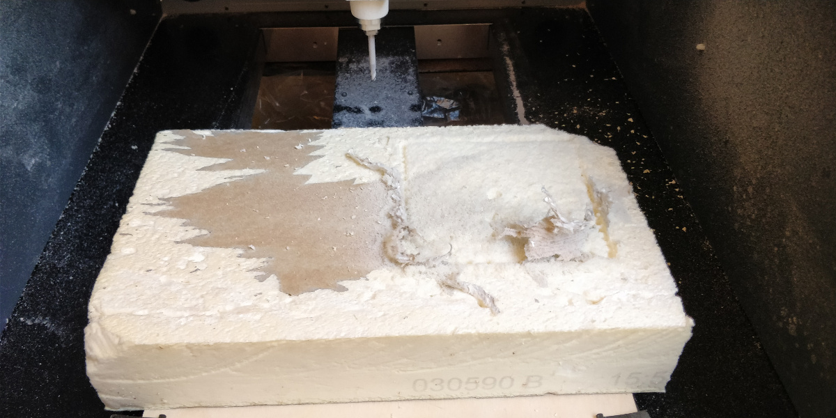
Figure 15. Roughing
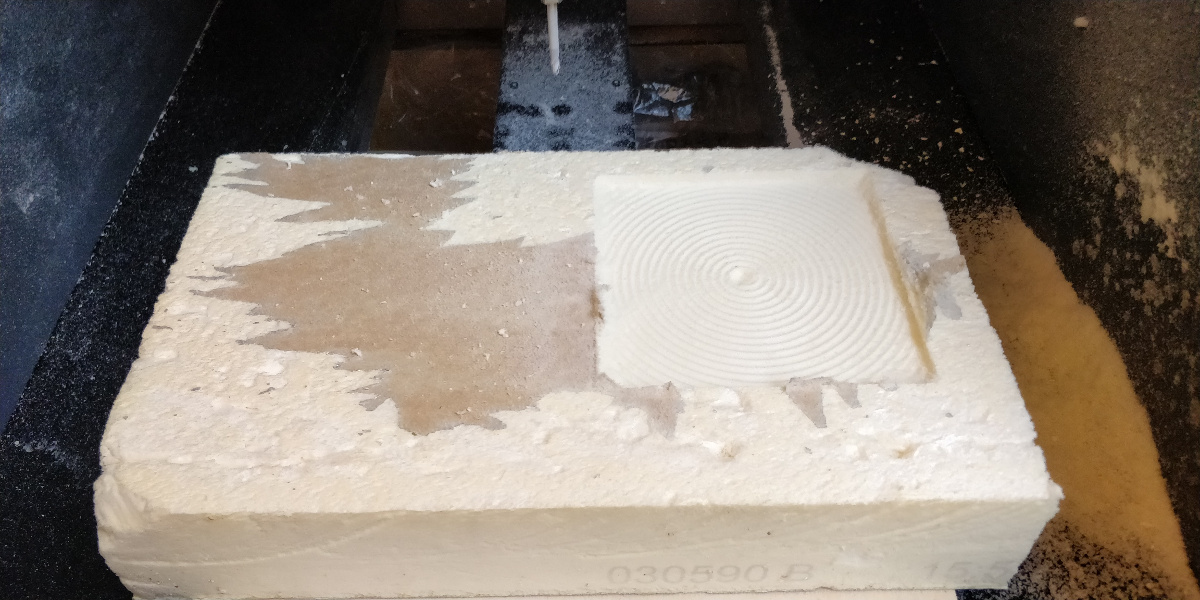
Figure 16. Roughing
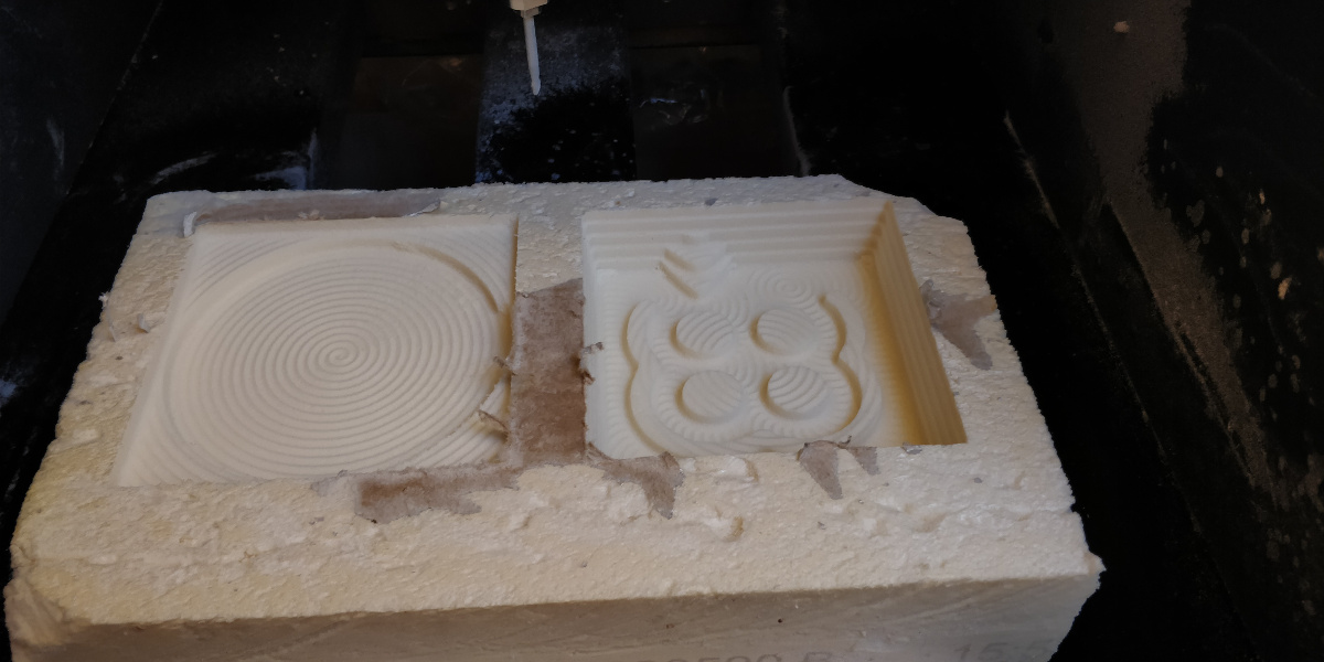
Figure 17. Roughing
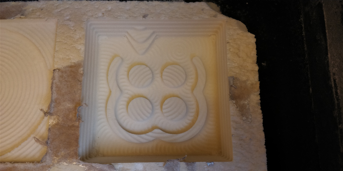
Figure 18. Roughing
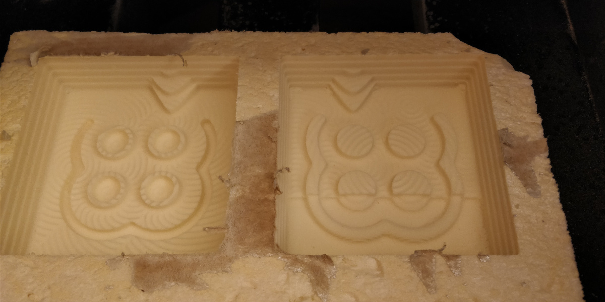
Figure 19. Finishing
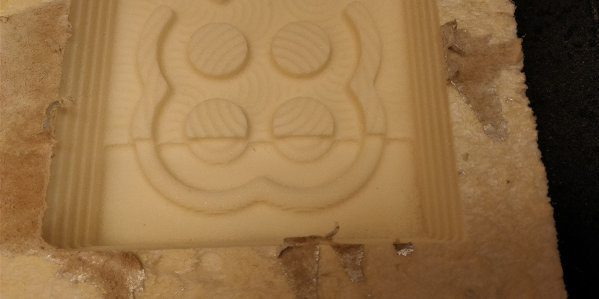
Figure 20. Finishing
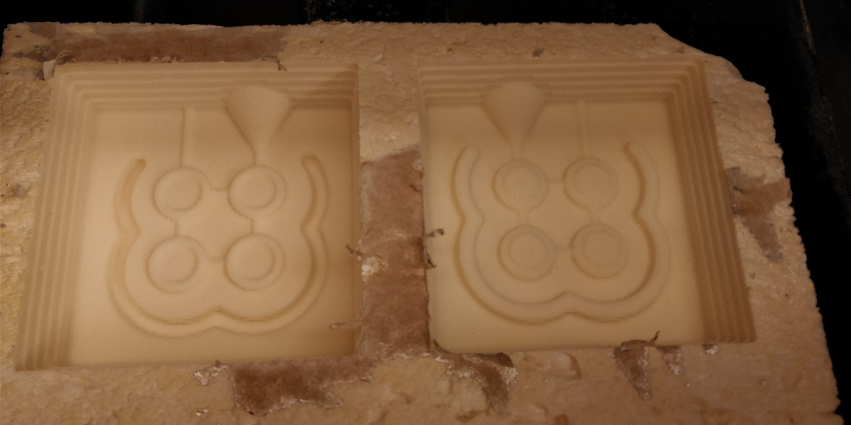
Figure 21. Finishing
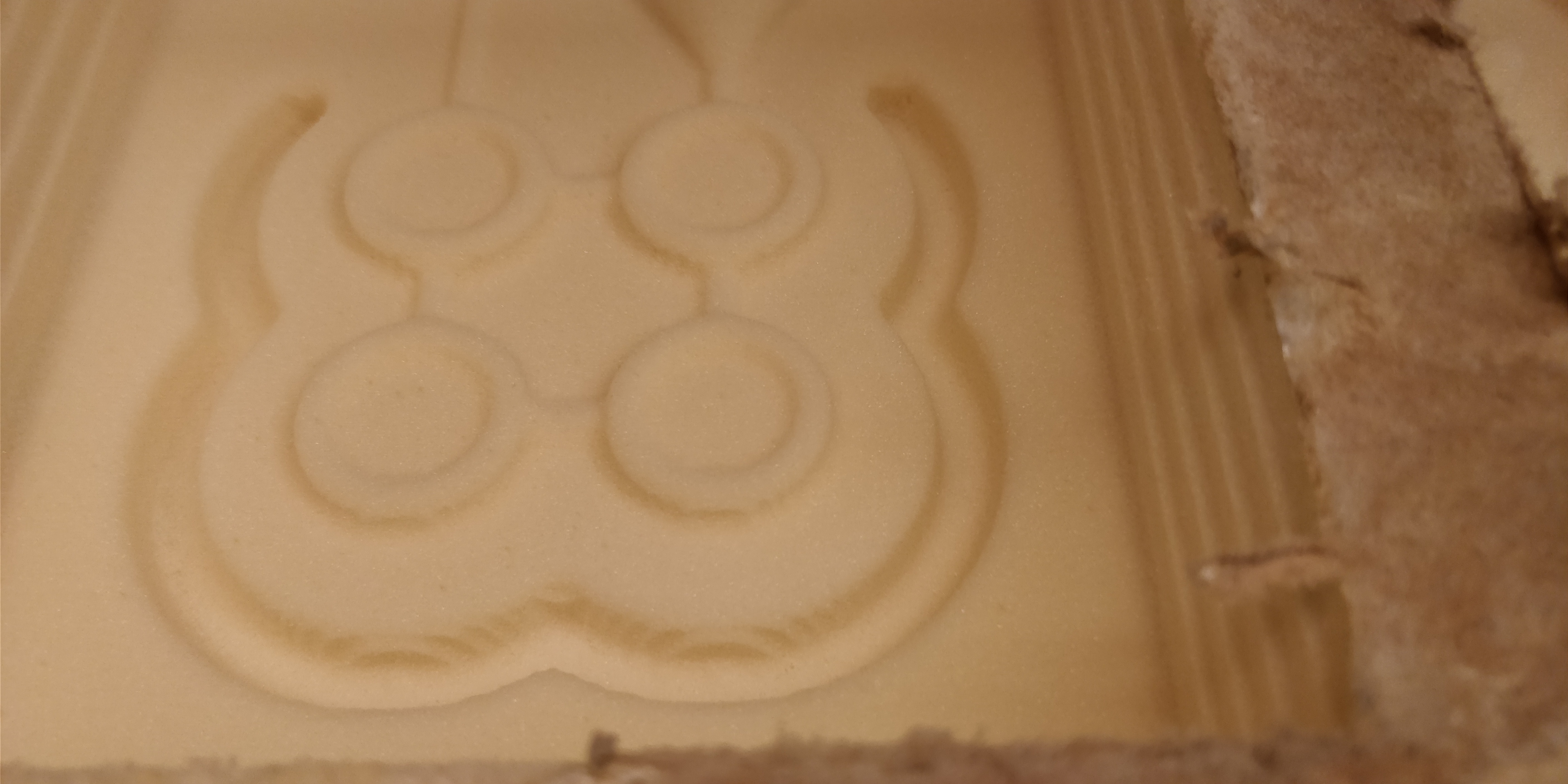
Figure 22. Finishing
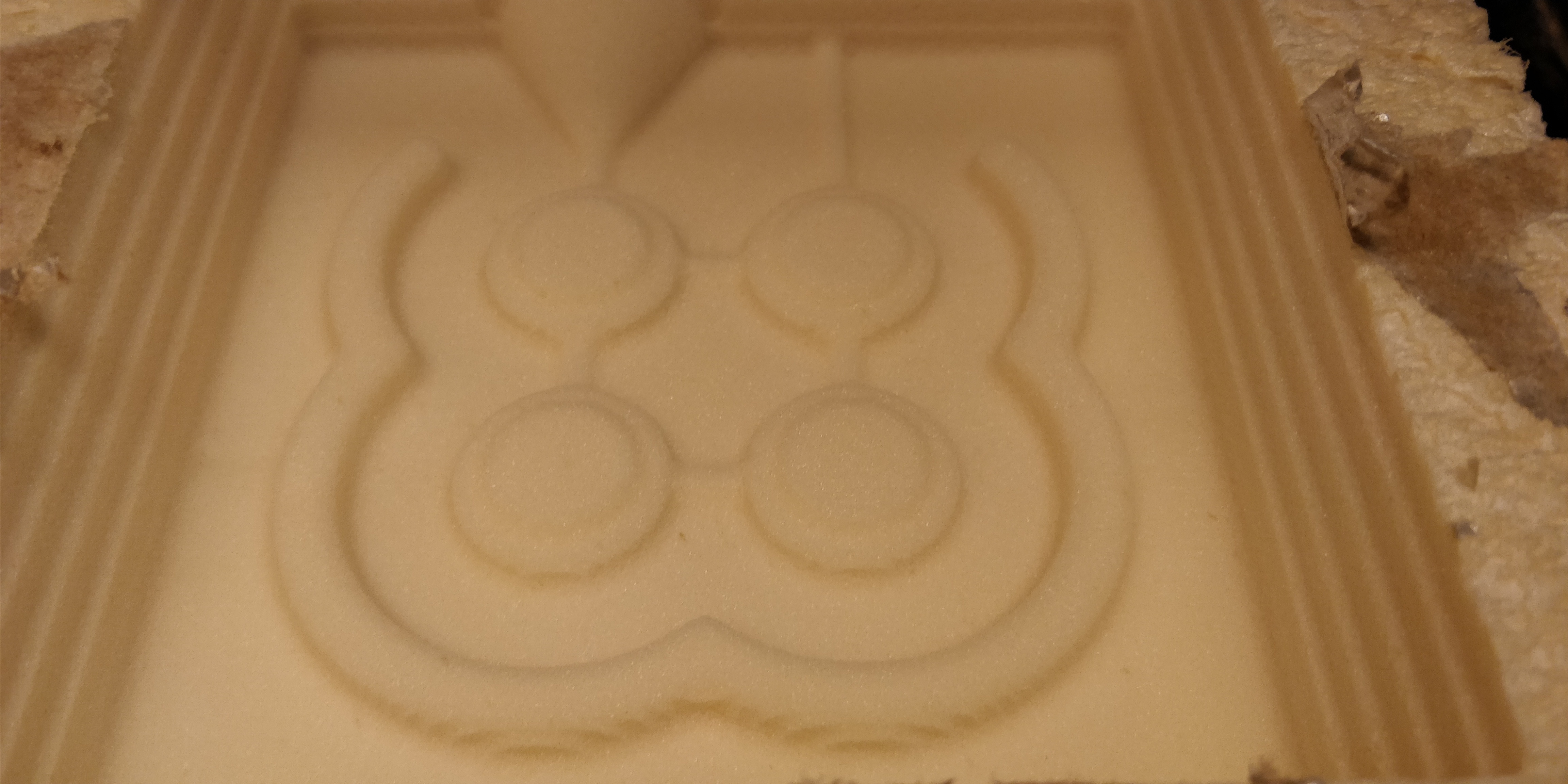
Figure 23. Finishing
Flat end mill
Once the ball end mill work was finished I inserted the flat end mill and put in contact with the copper base as before, but instead of zeroing I marked the value of the Z in User Coordinate System.
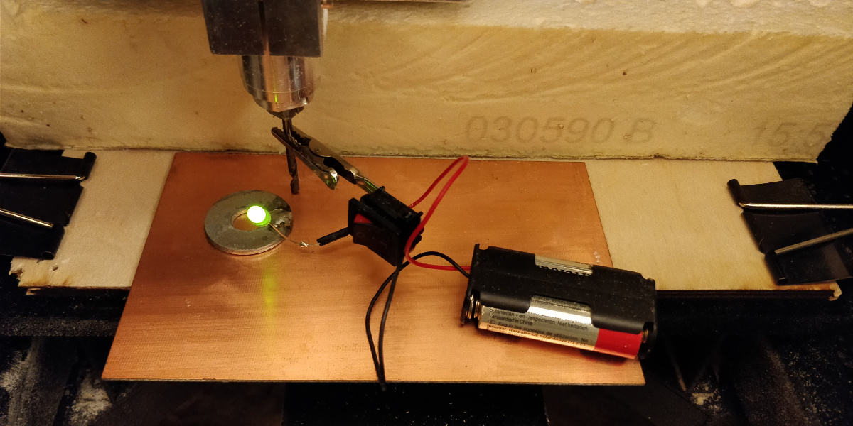
Figure 24. Z settings on machine for tool
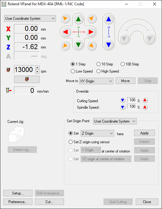
Figure 25. Z settings on PC for tool
Then from the G54 coordinate system I increased Z to the same value I marked before and set it as new Z Origin.
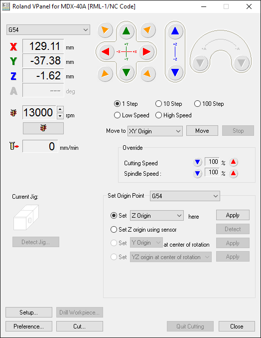
Figure 26. Z settings on PC to mill
This is the final result of the milling
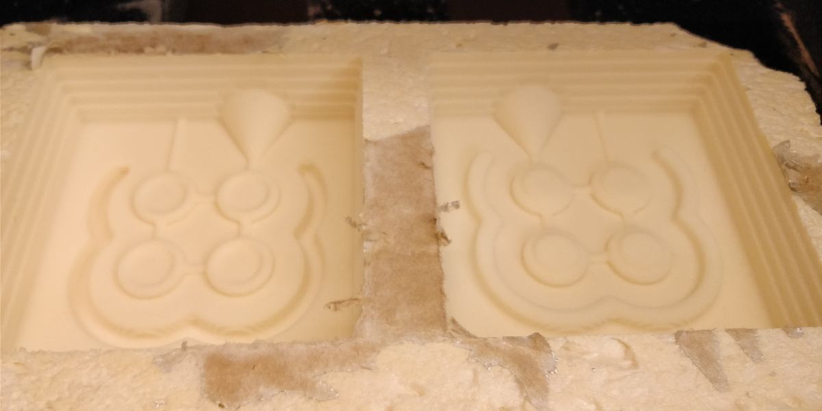
Figure 27. The block finished
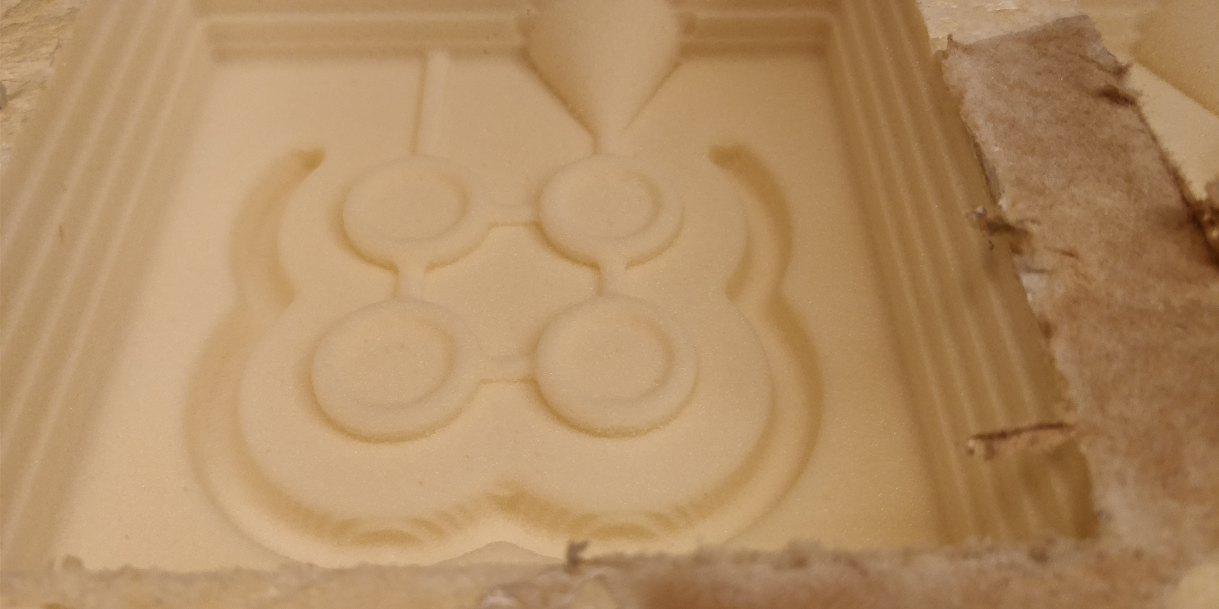
Figure 28. Part A finished
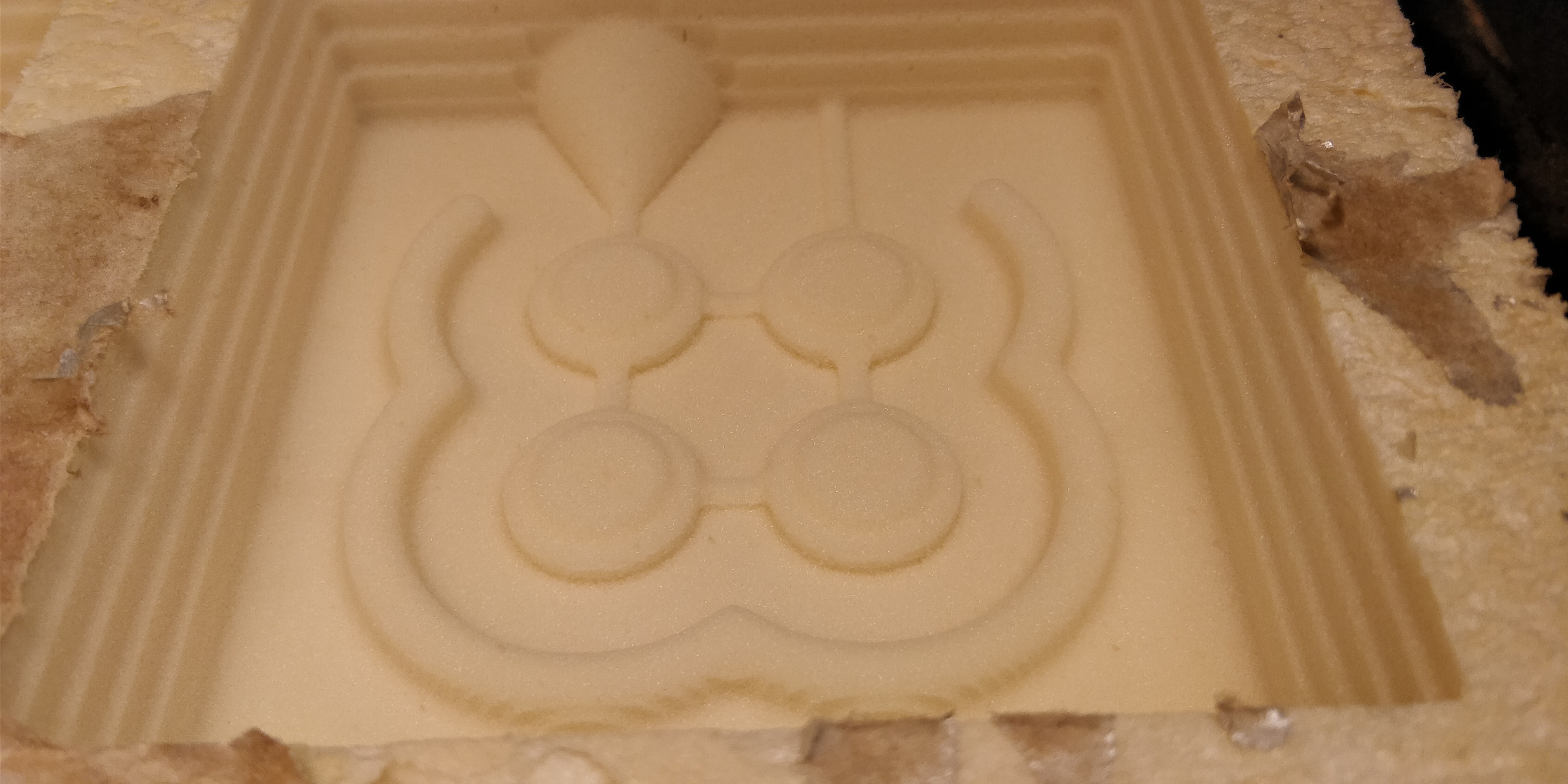
Figure 29. Part B finished
Molding
The material I chose for the mould is a white RTV BL30 silicone rubber with a blue catalyst. This also serves as a dye to help you understand if you have mixed the two compounds uniformly.
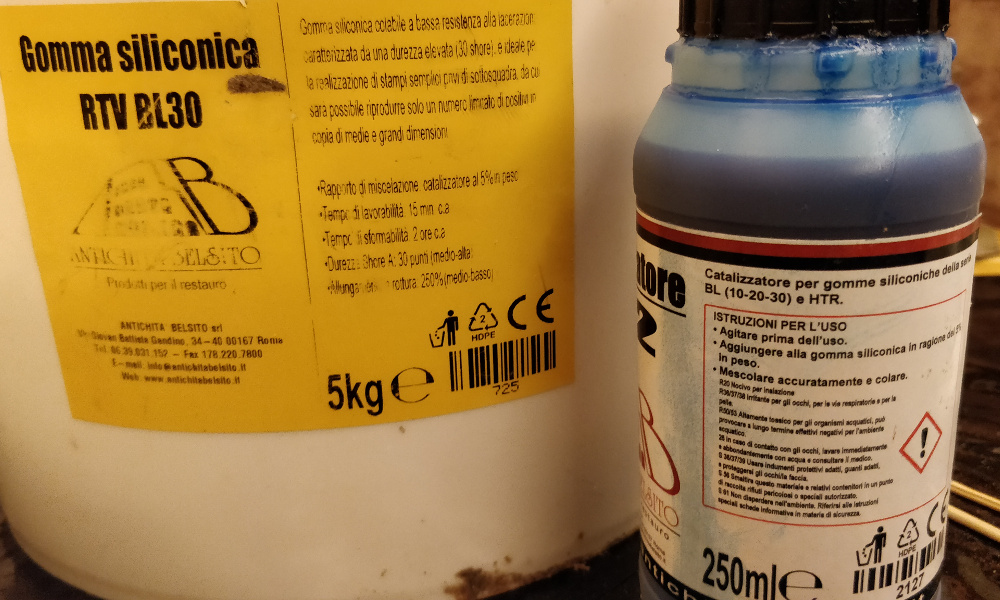
Figure 30. RTV BL30 silicone rubber
I poured the mix into a corner of the master to reduce the formation of air bubbles and waited two hours that catalyzes completely.
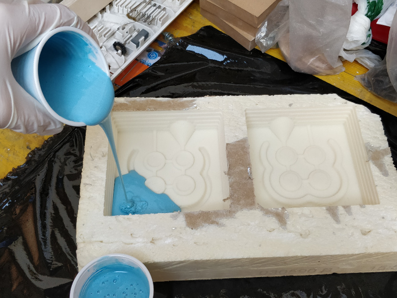
Figure 31. The pouring
In total I used 4 glasses of about 150g each with 5% catalyst added. Since the balance I used has an error of 1g I always kept a bit abundant, always approximating to excess.
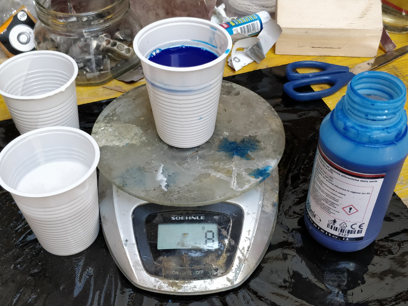
Figure 32. The scale
After the catalysis I easily removed the mold from the master but I damaged it. So I had to wash and dry the mold before I proceeded with the casting.
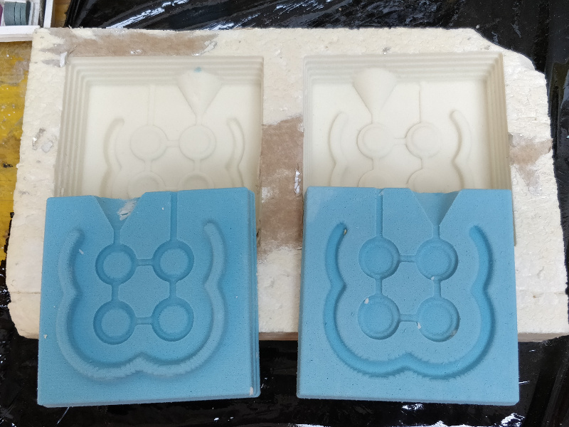
Figure 33. The molds
Casting
To get a satisfying result I had to make some tries with different mixes.
Plastic
The first attempt at casting was made with a two-component plastic to join the equal parts in volume.
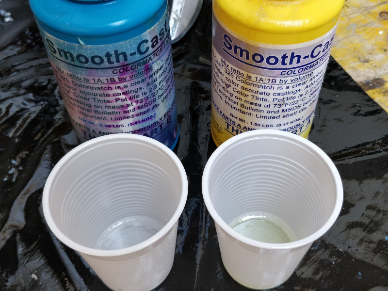
Figure 34. Smooth-Cast 325
Since the silicone is very soft I had to clamp it in the middle of two pieces of mdf to hold it in place. Then I proceeded with the casting.
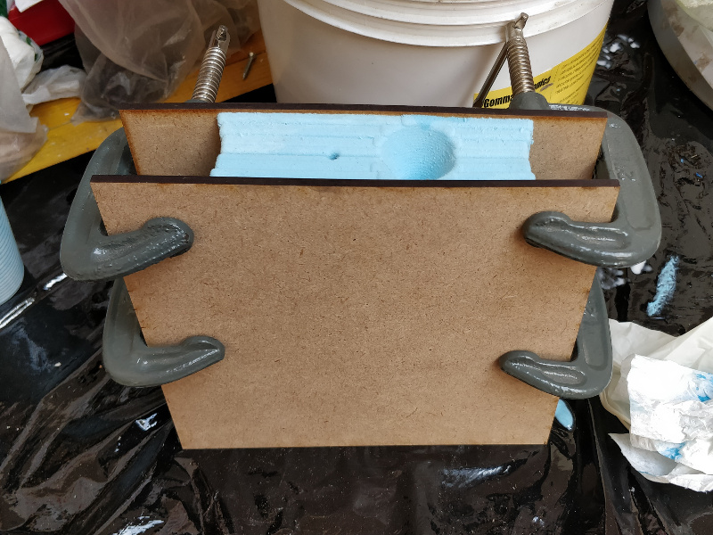
Figure 35. The clamps
Unfortunately, it has not catalysed correctly, probably because of the old age of the components.
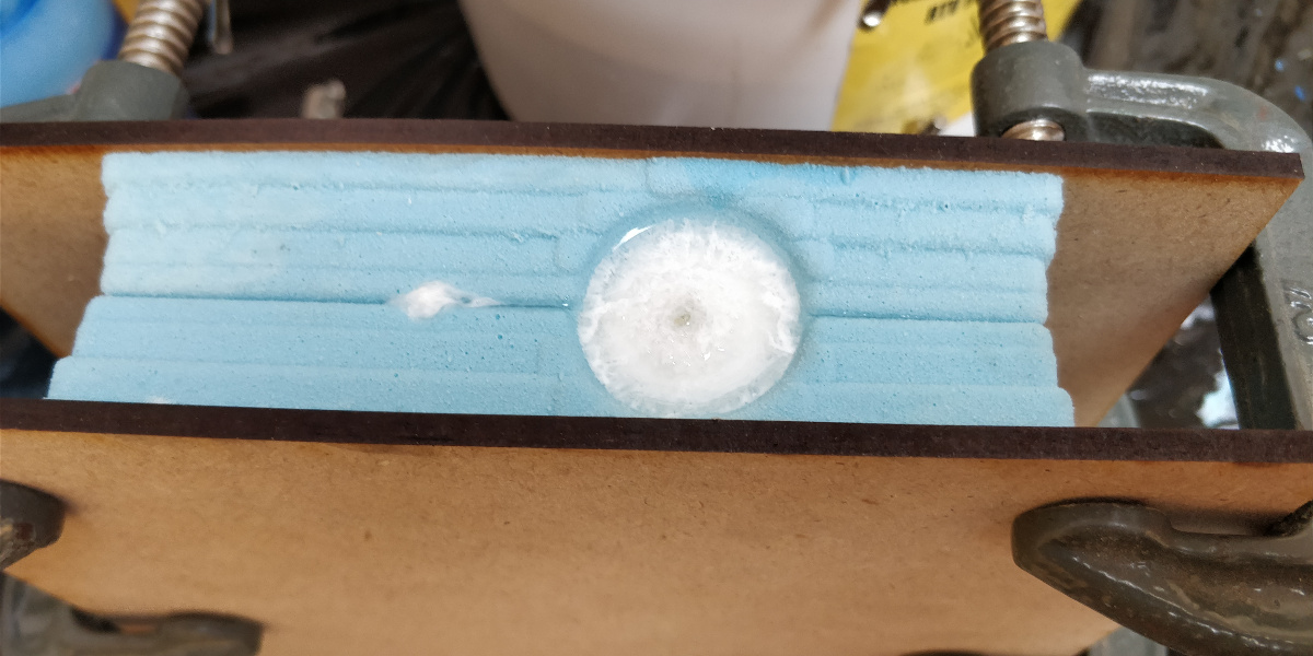
Figure 36. Long after casting
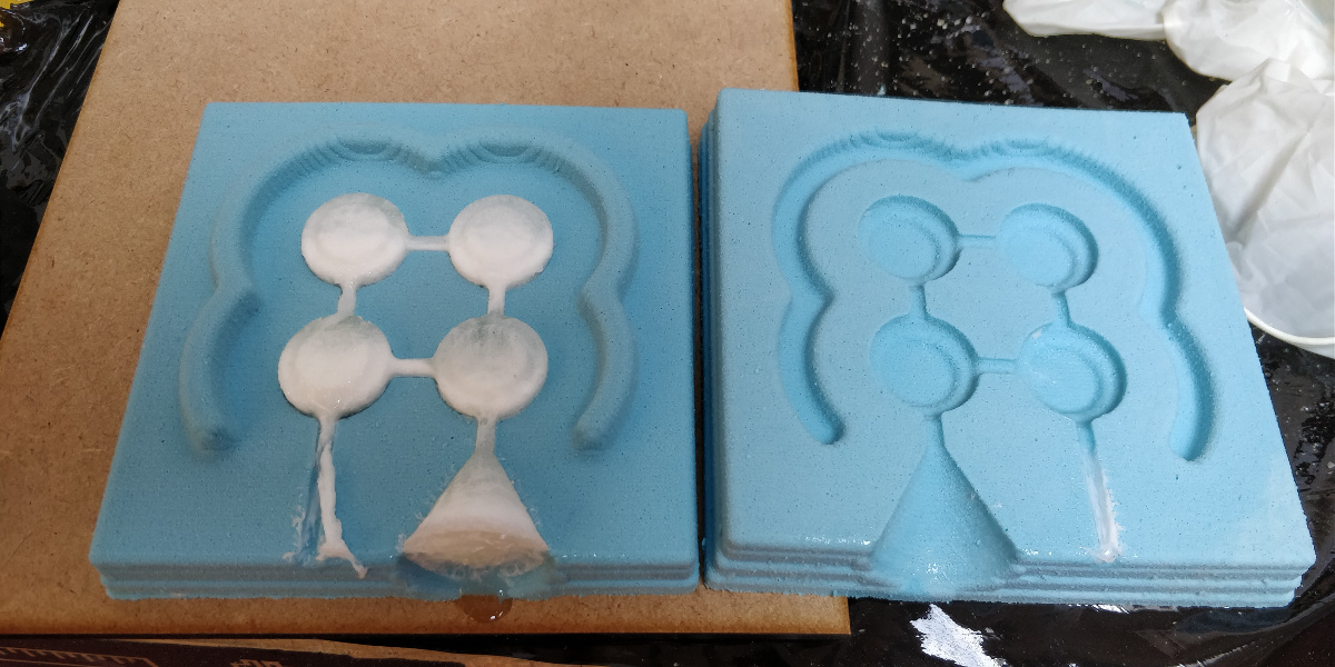
Figure 37. The mould opened
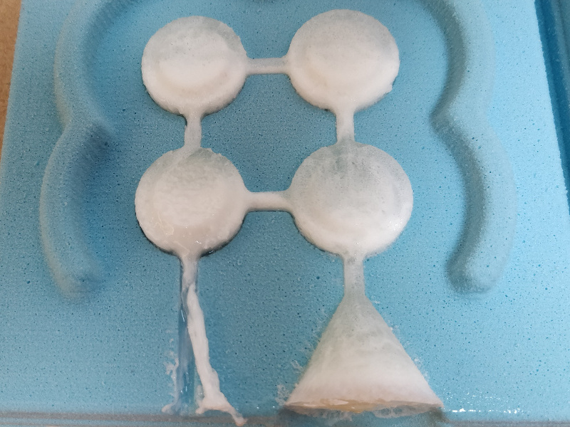
Figure 38. The plastic not catalysed correctly
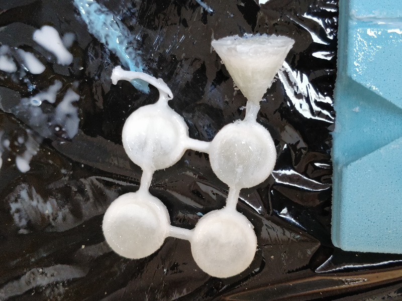
Figure 39. The plastic not catalysed correctly
Gypsum
The second attempt was made with a gypsum powder to be added with water.
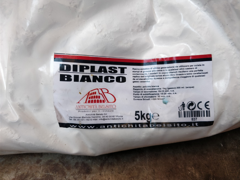
Figure 40. The gypsum
For the doses I looked at the mix for good density, but I put not much water and didn't fit well into all the pawns. In addition, there were many air bubbles, even large ones.
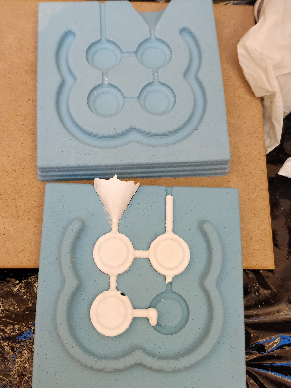
Figure 41. The first attempt
So I made one last attempt to dilute the gypsum more and the result was quite satisfactory even though some small air bubbles remained.
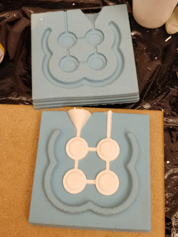
Figure 42. The second attempt
This is the end result after sanding the joints.
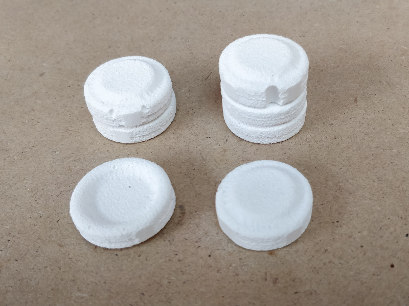
Figure 43. My pawn in gypsum
Group Assignment
More info on the Opendot group assignment page.