- Assignment 04
Electronics Production
In this week I milled and programmed a FabTinyISP with the Roland MODELA MDX-40A.
File
The starting file are two black and white PNG file with a resolution of 1000 DPI downloaded from the section FAB Fabrication of this guide.
I added a small hole with GIMP to customize it, so I also extended the other file.
download pcb 118 kB (.xcf)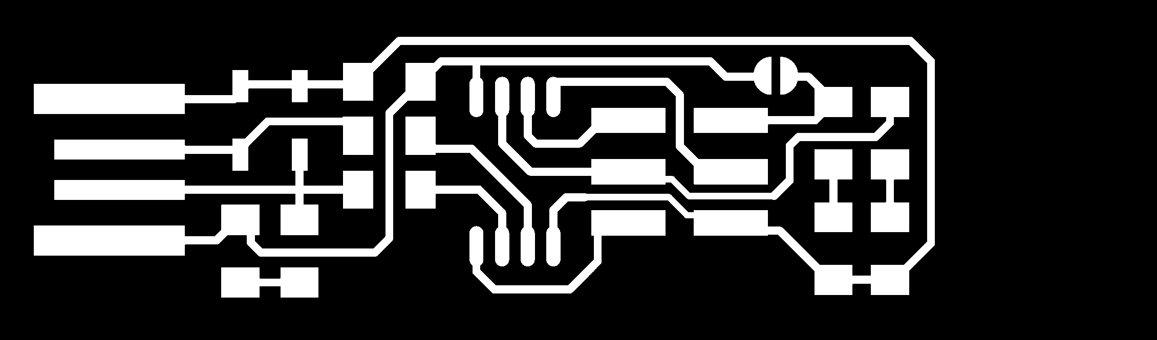
Figure 1. Traces

Figure 2. Outline
CAM
The CAM that I used is the online tool FabModules.
Traces
Starting from left to right I started importing the image pcb-traces.png, selected Roland mill
(.rml) like output format and PCB traces (1/64) like process.
On right column I set MDX-40 as machine and only 2 as number of offsets.
Before saving the file I calculated the tracks.
download pcb-traces 17,4 kB (.rml)
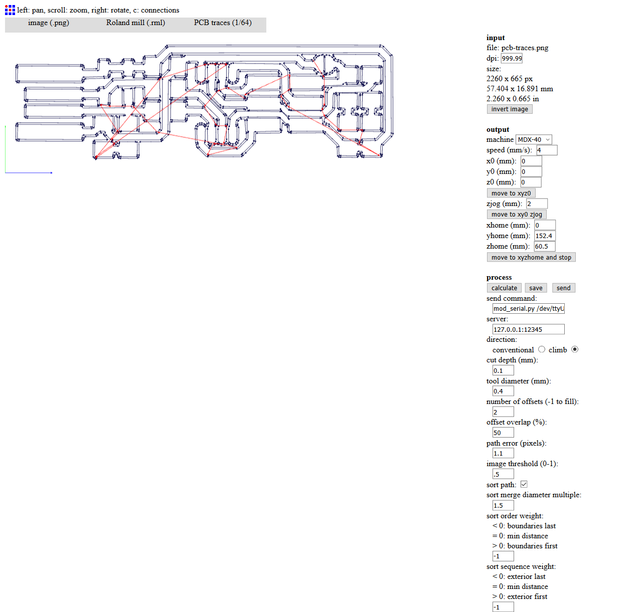
Figure 3. Traces in FabModules
Outline
I repeated same procedure with pcb-outline.png using PCB outline (1/32) like process and changing the tool diameter in 2.
download pcb-outline 2,93 kB (.rml)
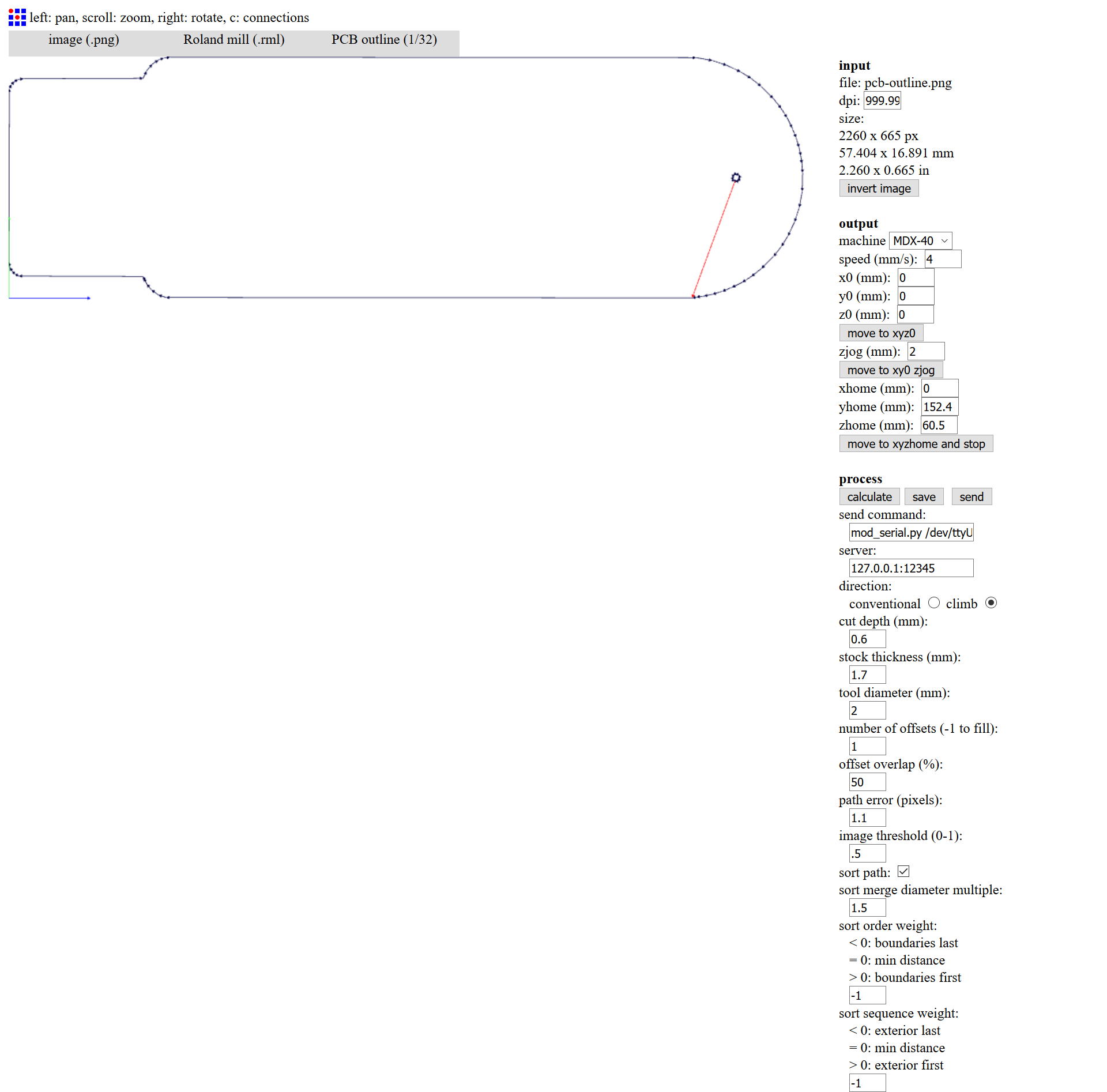
Figure 4. Outline in FabModules
Milling Machine
I used two different tips to build the PCB, one for process.
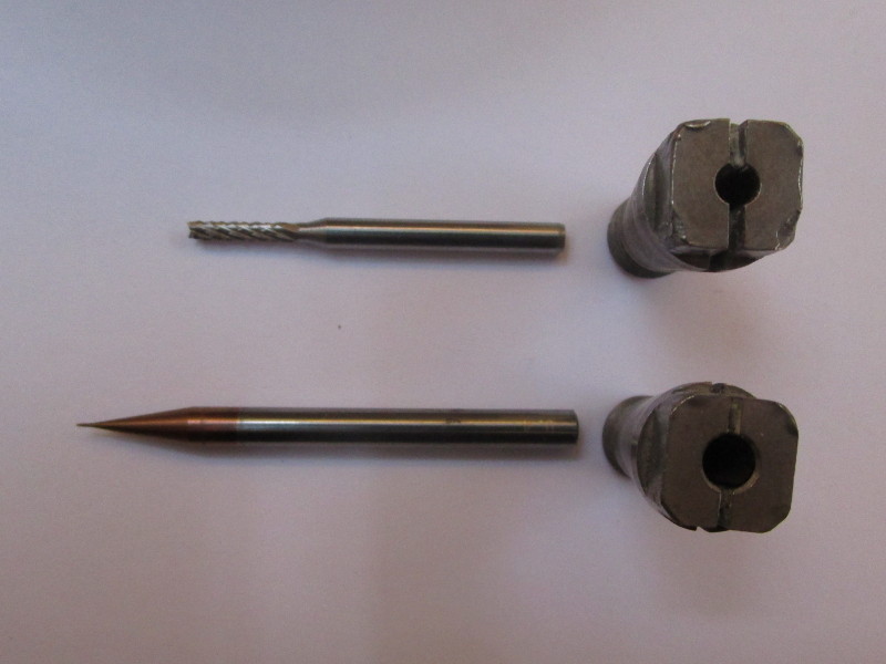
Figure 5. 0.4 and 2mm tips
Unfortunately I forgot to take the photos during the making of my board, so I made them again making the board for Fabkit (which is slightly different, but the process is identical).
Copper PC Board
First I took a Copper PC Board single sided large enough and glued it with the double-sided adhesive tape to the worktable.
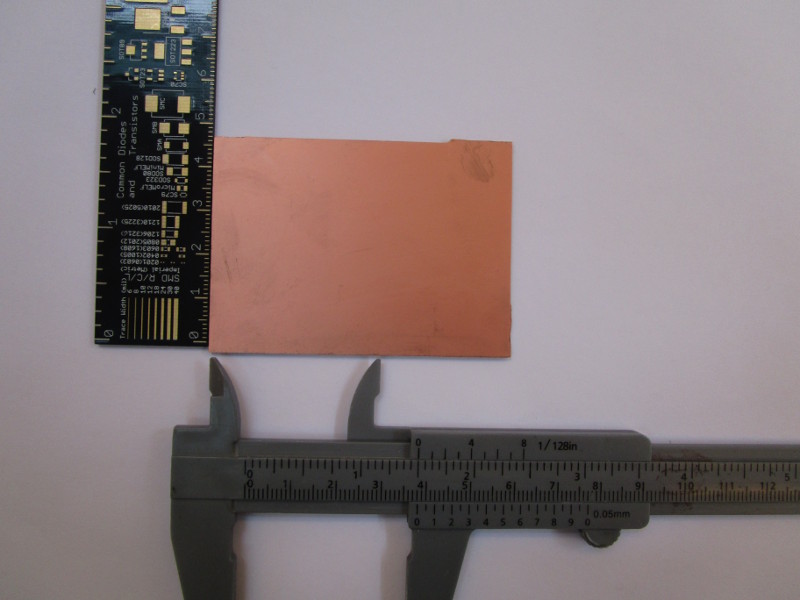
Figure 6. Copper PC Board
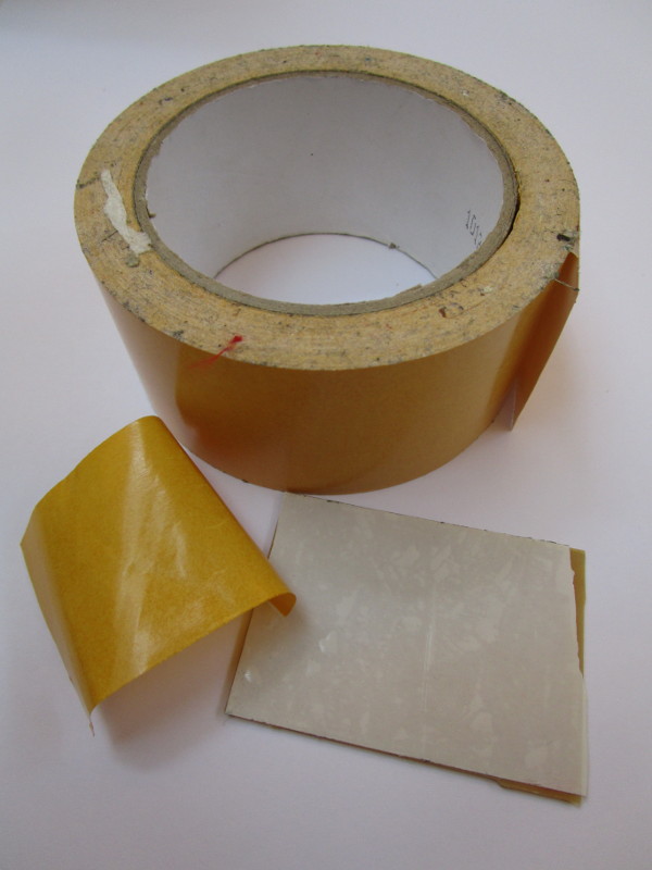
Figure 7. Double-sided adhesive tape
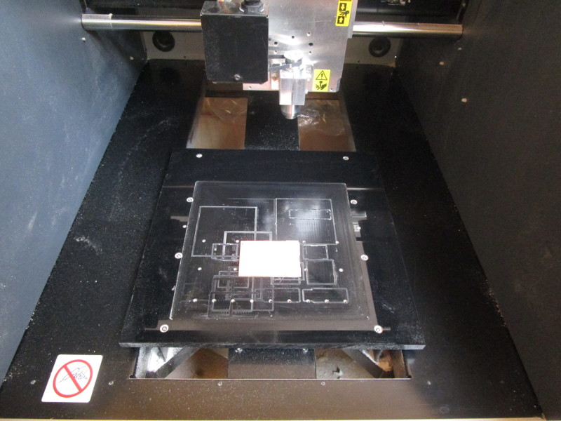
Figure 8. Copper PC Board on the worktable
Traces
After inserting the 0.4 mm tip, I found the relative origin of the axes. I did it in two stages, first X
and Y (using red and green arrows on the software) and after Z (using blue arrows). It is important that the
Z value is very precise for milling the tracks correctly, to
find the right height I used an ingenious DIY system that closing the circuit between the tip and the board
a led lights up.
By clicking on Apply in the Set Origin Point section I set to zero the relative origin of the
axes.
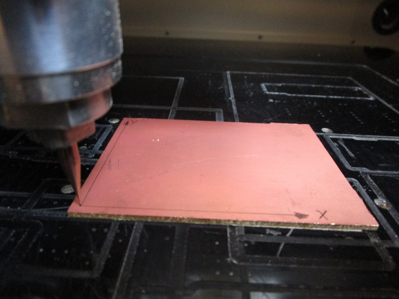
Figure 9. Relative origin of X and Y
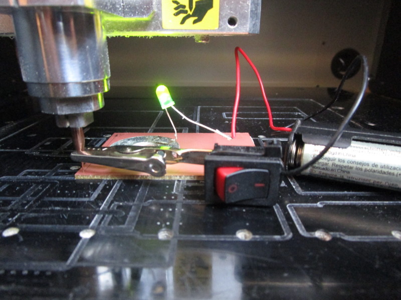
Figure 10. The ingenious DIY system fo Z
Clicking on Cut... opened a window from which I selected the file pcb-traces.rml and sent it to the machine.
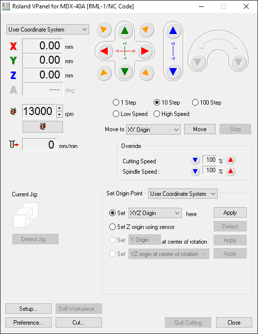
Figure 11. Software
For safety reasons, the machine does not start with the door open...
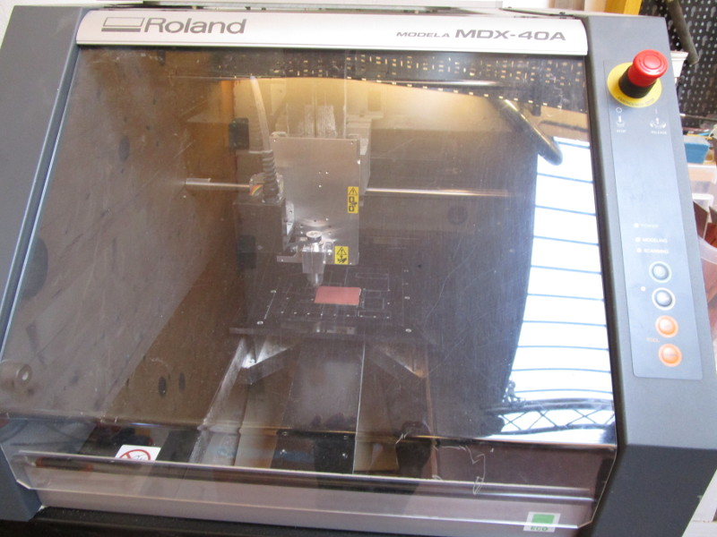
Figure 12. The machine with the door close
This is the result after milling the tracks.
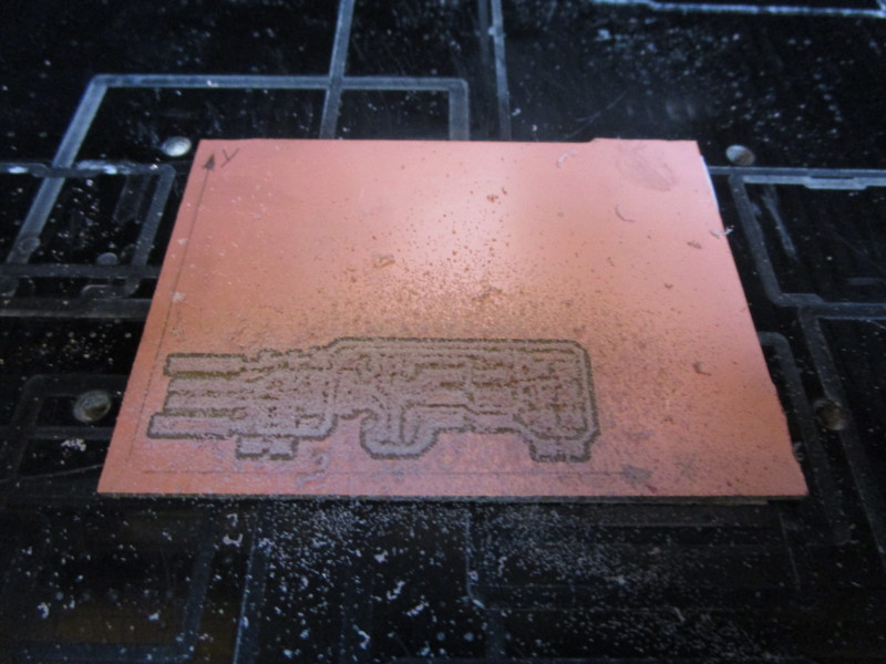
Figure 13. Tracks
Outline
To cut the outline I had to change the tip to 2mm and set the Z axis again, this time with a sheet as less precision is needed for this process.
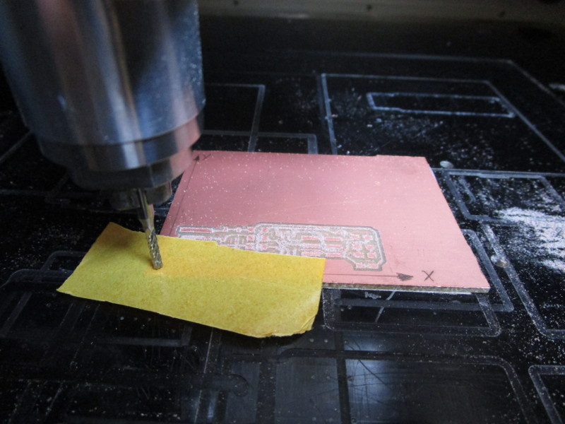
Figure 14. Less precision system for Z
This is the final result .
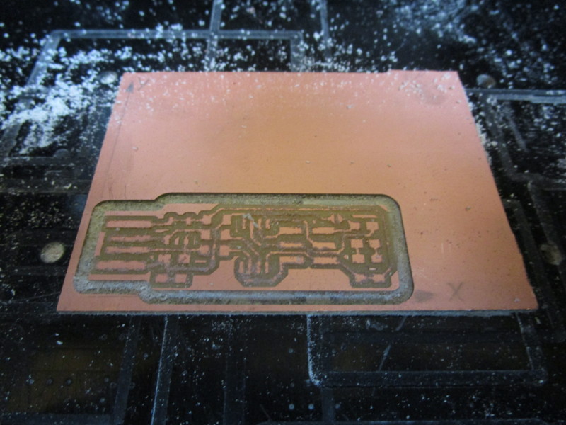
Figure 15. Tracks and outline
Soldering
Before proceeding with the soldering I cleaned the board with a kitchen sponge and with isopropyl alcohol and
with the cutter I removed the extra parts of the usb connector.
To keep the base blocked to the table I used the double-sided adhesive tape.
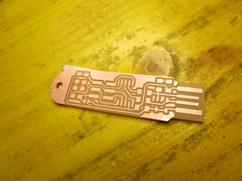
Figure 16. PCB cleaned
To make soldering easier I first tinplated a pad for each component, then with tweezers I positioned and soldered the components one by one.
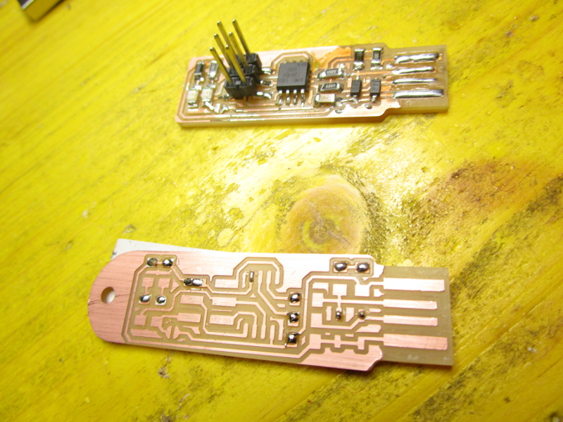
Figure 17. A pad tinplated for each component
This is the final result:
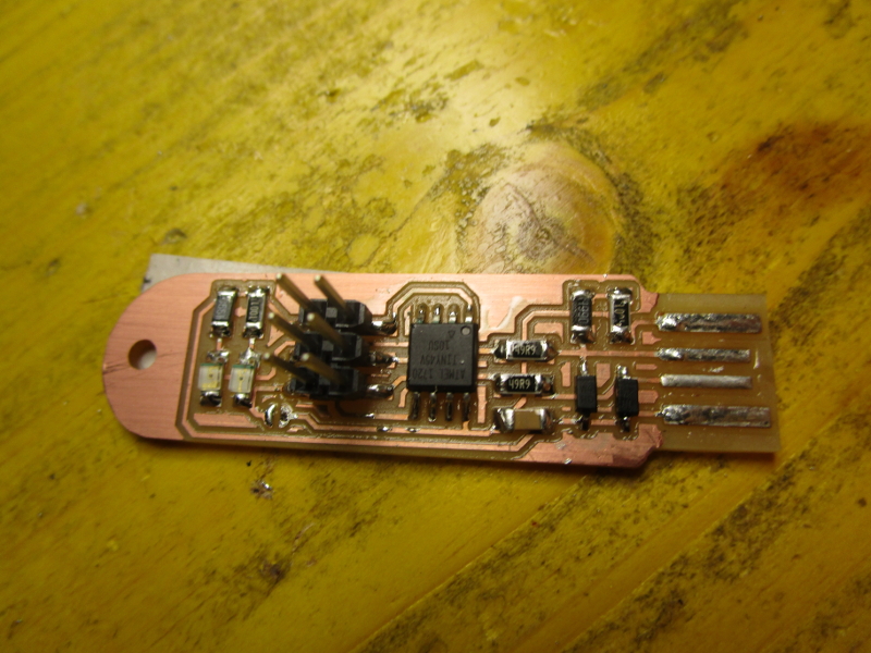
Figure 18. PCB populated
Testing
To test the board I loaded the sketch to turn it into a programmer.
Requirement
To compile and load the firmware I had to install three programs and drivers, and then update the system
variables to run the programs installed from the terminal.
Between installing a program and checking it I needed to add the installation folder to the
Environment Variables, to do this I followed the section Update your PATH of
this guide.
GNU Make
GNU Make is used to run the Makefile,
very useful to avoid needing to write a long series of commands from the terminal.
I verified the installation was successful by Command Prompt by typing make -v .
C:\Users\Paso>make -v
GNU Make 3.81
Copyright (C) 2006  Free Software Foundation, Inc.
This is free software; see the source for copying conditions.
There is NO warranty; not even for MERCHANTABILITY or FITNESS FOR A
PARTICULAR PURPOSE.

This program built for i386-pc-mingw32
AVR 8-bit Toolchain
AVR 8-bit Toolchain
is used to compile in hexadecimal format the sketch to be sent to the AVRs (ATtiny45 in this case).
I verified the installation was successful by Command Prompt by typing avr-gcc --version .
C:\Users\Paso>avr-gcc --version
avr-gcc (AVR_8_bit_GNU_Toolchain_3.5.4_1709) 4.9.2
Copyright (C) 2014 Free Software Foundation, Inc.
This is free software; see the source for copying conditions.  There is NO
warranty; not even for MERCHANTABILITY or FITNESS FOR A PARTICULAR PURPOSE.
AVRDUDE
AVRDUDE is used to send a hexadecimal file to AVR.
I verified the installation was successful by Command Prompt by typing avrdude -? .
C:\Users\Paso>avrdude -?
Usage: avrdude [options]
Options:
  [...]

avrdude version 5.11, URL: <http://savannah.nongnu.org/projects/avrdude/>
Drivers
I downloaded the drivers from an Adafruit tutotial and in the installer I made sure that the voice Trinket / Pro Trinket / Gemma (USBtinyISP) was checked.
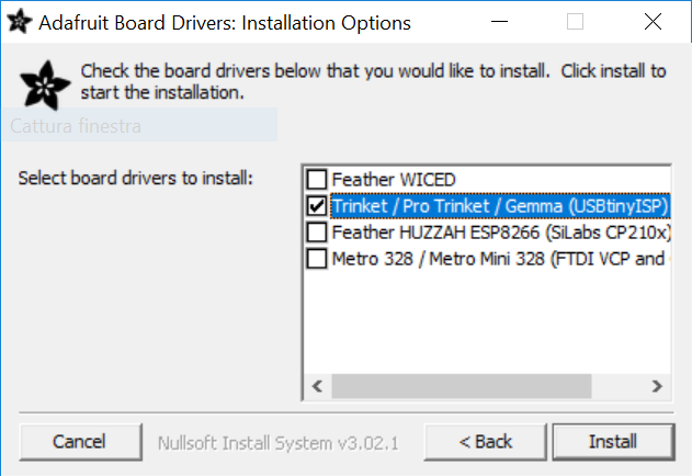
Figure 18. USBtinyISP Drivers Installer
Flashing
In section Get and Build the Firmware of
this guide I downloaded
the firmware and after having extracted the folder I entered it from the terminal by typing
cd C:\Users\Paso\FabAcademy\fts_firmware_bdm_v1 .
Afterwards I connected the board to the programmer (another FabTinyISP) and both to my PC
(mine only to be able to power it).
make
I compiled the firmware by typing make .
C:\Users\Paso\FabAcademy\fts_firmware_bdm_v1>make
avr-gcc -mmcu=attiny45 -Wall -DF_CPU=16500000UL -I. -funsigned-char -funsigned-bitfields -fpack-struct -fshort-enums -Os -Iusbdrv -c main.c -o main.o
main.c:109:13: warning: always_inline function might not be inlinable [-Wattributes]
static void delay ( void )
^
avr-gcc -mmcu=attiny45 -Wall -DF_CPU=16500000UL -I. -funsigned-char -funsigned-bitfields -fpack-struct -fshort-enums -Os -Iusbdrv -c usbdrv/usbdrv.c -o usbdrv/usbdrv.o
avr-gcc -mmcu=attiny45 -Wall -DF_CPU=16500000UL -I. -funsigned-char -funsigned-bitfields -fpack-struct -fshort-enums -Os -Iusbdrv -c usbdrv/oddebug.c -o usbdrv/oddebug.o
avr-gcc -x assembler-with-cpp -mmcu=attiny45 -Wall -DF_CPU=16500000UL -I. -funsigned-char -funsigned-bitfields -fpack-struct -fshort-enums -Os -Iusbdrv -c usbdrv/usbdrvasm.S -o usbdrv/usbdrvasm.o
avr-gcc -mmcu=attiny45 -o fts_firmware.elf main.o usbdrv/usbdrv.o usbdrv/oddebug.o usbdrv/usbdrvasm.o
avr-size -C --mcu=attiny45 fts_firmware.elf
AVR Memory Usage
----------------
Device: attiny45

Program:    2474 bytes (60.4% Full)
(.text + .data + .bootloader)

Data:         75 bytes (29.3% Full)
(.data + .bss + .noinit)


avr-objcopy -j .text -j .data -O ihex fts_firmware.elf fts_firmware.hex
flash
I flashed the firmware by typing make flash .
C:\Users\Paso\FabAcademy\fts_firmware_bdm_v1>make flash
avrdude -p attiny45 -c usbtiny -P usb -e \
-U flash:w:fts_firmware.hex

avrdude: AVR device initialized and ready to accept instructions

Reading | ################################################## | 100% 0.01s

avrdude: Device signature = 0x1e9206
avrdude: erasing chip
avrdude: reading input file "fts_firmware.hex"
avrdude: input file fts_firmware.hex auto detected as Intel Hex
avrdude: writing flash (2474 bytes):

Writing | ################################################## | 100% 4.24s


avrdude: 2474 bytes of flash written
avrdude: verifying flash memory against fts_firmware.hex:
avrdude: load data flash data from input file fts_firmware.hex:
avrdude: input file fts_firmware.hex auto detected as Intel Hex
avrdude: input file fts_firmware.hex contains 2474 bytes
avrdude: reading on-chip flash data:

Reading | ################################################## | 100% 2.87s


avrdude: verifying ...
avrdude: 2474 bytes of flash verified

avrdude: safemode: Fuses OK

avrdude done.  Thank you.
fuses
I set up all of the fuses except the one that disables the reset pin by typing make fuses .
C:\Users\Paso\FabAcademy\fts_firmware_bdm_v1>make fuses
avrdude -p attiny45 -c usbtiny -P usb \
                -U lfuse:w:0xE1:m -U hfuse:w:0xDD:m \
                -U efuse:w:0xFF:m

avrdude: AVR device initialized and ready to accept instructions

Reading | ################################################## | 100% 0.01s

avrdude: Device signature = 0x1e9206
avrdude: reading input file "0xE1"
avrdude: writing lfuse (1 bytes):

Writing | ################################################## | 100% 0.01s

avrdude: 1 bytes of lfuse written
avrdude: verifying lfuse memory against 0xE1:
avrdude: load data lfuse data from input file 0xE1:
avrdude: input file 0xE1 contains 1 bytes
avrdude: reading on-chip lfuse data:

Reading | ################################################## | 100% 0.01s

avrdude: verifying ...
avrdude: 1 bytes of lfuse verified
avrdude: reading input file "0xDD"
avrdude: writing hfuse (1 bytes):

Writing | ################################################## | 100% 0.02s

avrdude: 1 bytes of hfuse written
avrdude: verifying hfuse memory against 0xDD:
avrdude: load data hfuse data from input file 0xDD:
avrdude: input file 0xDD contains 1 bytes
avrdude: reading on-chip hfuse data:

Reading | ################################################## | 100% 0.01s

avrdude: verifying ...
avrdude: 1 bytes of hfuse verified
avrdude: reading input file "0xFF"
avrdude: writing efuse (1 bytes):

Writing | ################################################## | 100% 0.01s

avrdude: 1 bytes of efuse written
avrdude: verifying efuse memory against 0xFF:
avrdude: load data efuse data from input file 0xFF:
avrdude: input file 0xFF contains 1 bytes
avrdude: reading on-chip efuse data:

Reading | ################################################## | 100% 0.01s

avrdude: verifying ...
avrdude: 1 bytes of efuse verified

avrdude: safemode: Fuses OK

avrdude done.  Thank you.
rstdisbl
I set up all of the fuses, this time include the one that disables the reset pin, by typing
make rstdisbl .
C:\Users\Paso\FabAcademy\fts_firmware_bdm_v1>make rstdisbl
avrdude -p attiny45 -c usbtiny -P usb \
-U lfuse:w:0xE1:m -U hfuse:w:0x5D:m \
-U efuse:w:0xFF:m

avrdude: AVR device initialized and ready to accept instructions

Reading | ################################################## | 100% 0.09s

avrdude: Device signature = 0x1e9206
avrdude: reading input file "0xE1"
avrdude: writing lfuse (1 bytes):

Writing | ################################################## | 100% 0.03s

avrdude: 1 bytes of lfuse written
avrdude: verifying lfuse memory against 0xE1:
avrdude: load data lfuse data from input file 0xE1:
avrdude: input file 0xE1 contains 1 bytes
avrdude: reading on-chip lfuse data:

Reading | ################################################## | 100% 0.03s

avrdude: verifying ...
avrdude: 1 bytes of lfuse verified
avrdude: reading input file "0x5D"
avrdude: writing hfuse (1 bytes):

Writing | ################################################## | 100% 0.05s

avrdude: 1 bytes of hfuse written
avrdude: verifying hfuse memory against 0x5D:
avrdude: load data hfuse data from input file 0x5D:
avrdude: input file 0x5D contains 1 bytes
avrdude: reading on-chip hfuse data:

Reading | ################################################## | 100% 0.04s

avrdude: verifying ...
avrdude: 1 bytes of hfuse verified
avrdude: reading input file "0xFF"
avrdude: writing efuse (1 bytes):

Writing | ################################################## | 100% 0.02s

avrdude: 1 bytes of efuse written
avrdude: verifying efuse memory against 0xFF:
avrdude: load data efuse data from input file 0xFF:
avrdude: input file 0xFF contains 1 bytes
avrdude: reading on-chip efuse data:

Reading | ################################################## | 100% 0.01s

avrdude: verifying ...
avrdude: 1 bytes of efuse verified

avrdude: safemode: Fuses OK

avrdude done.  Thank you.
Check
I checked if the USB on board works looking in Device Manager
(Start → Control Panel → System → Device Manager).
Finally I desoldered the SOLDER_JUMPER connected with Vcc.
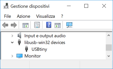
Figure 19. USBtiny in Device Manager
Group Assignment
More info on the Opendot group assignment page.