- Assignment 06
Electronics Design
The goal of this week is to design a programmable board and make it. I copied the circuit of echo hello-world and I added a led with relative resistance and a button.
Design
To design I evaluated two CADs: EAGLE and KiCad. I already used KiCad, but I chose EAGLE 8.7.0, because a library with all components was already available.
Library
The components used in the schematic were all present in the
library available in the
schedule of the week.
Unfortunately opening the link in my browser (Firefox) doesn't start the download, but opens it as text, so
I copied it in a new file and renamed it fab.lib. Afterward I move the library in the EAGLE
Projects folder.
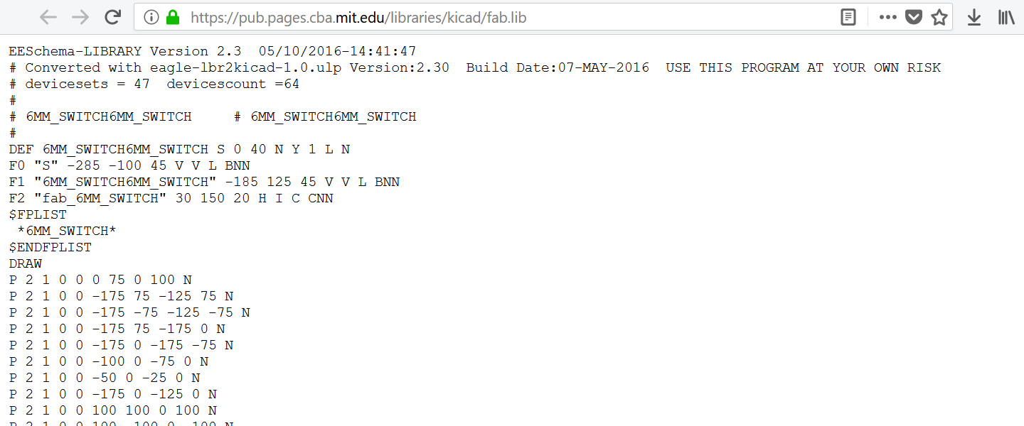
Figure 1. fab.lib in Firefox
To use the library I need to enable it, so I clicked on the small dot to the right of the library name in the Eagle main screen. When the dot is green, it is enabled; if it is grey, it is disabled.
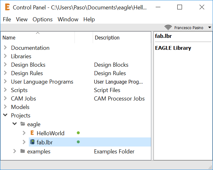
Figure 2. EAGLE main screen
Schematic
In the toolbar I clicked on File -> New -> Project and then on File -> New -> Schematic. As names I always used HelloBoard.
I included all the necessary components by Add command. I always chose SMD components with FAB in the name, if available.
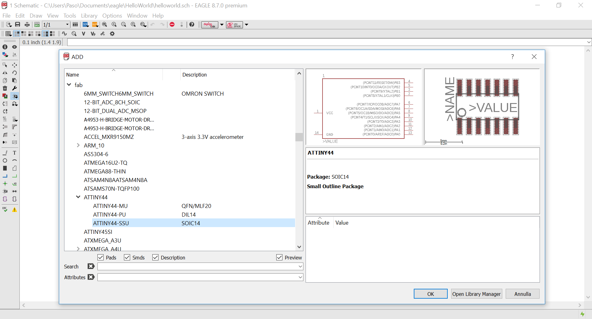
Figure 3. Add screen
I moved and turned the components until I found a solution I liked and then I made the nets using also a lot of labels to create a very clean schematic.
download helloworld 80,1 kB (.sch)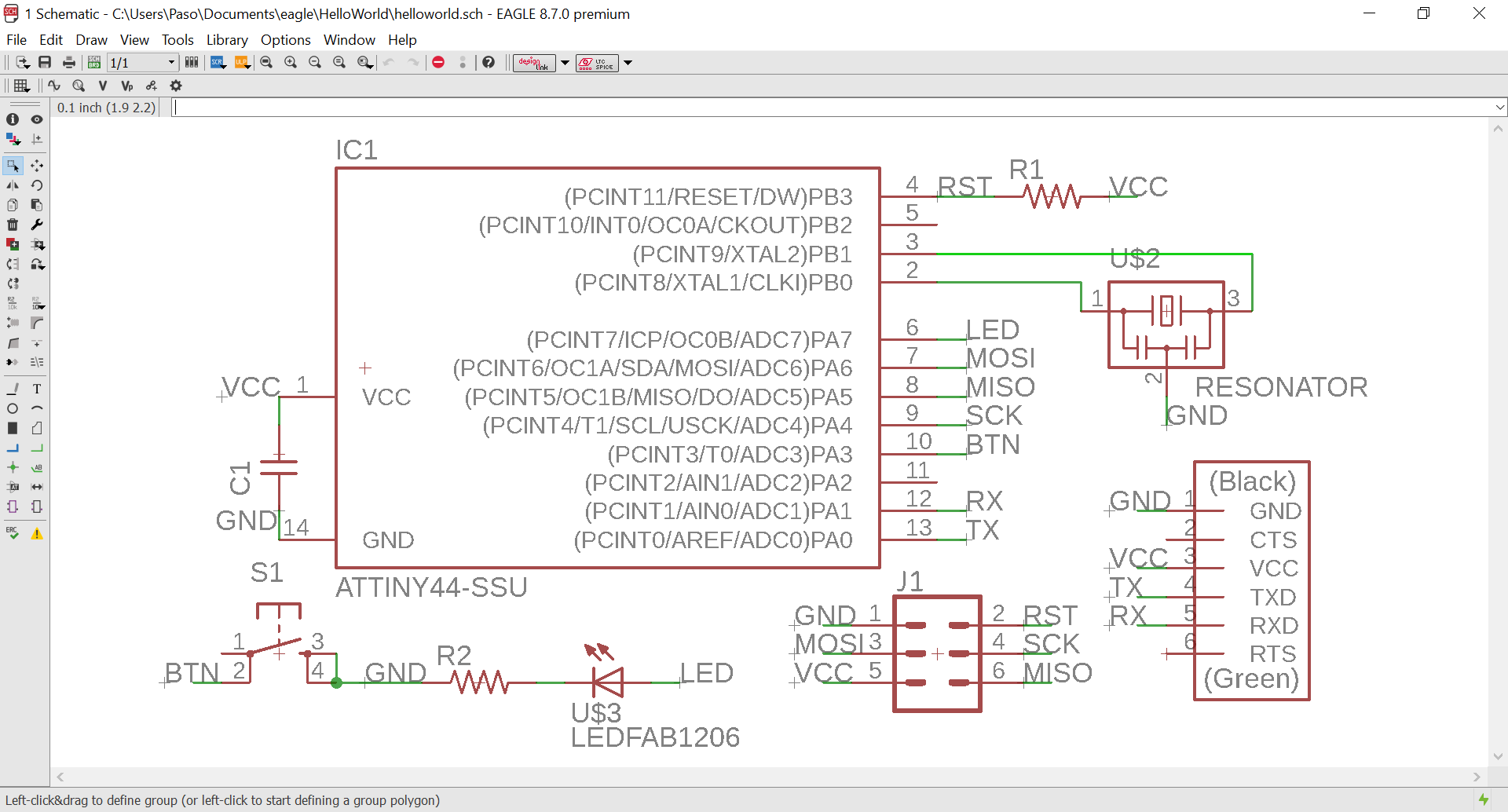
Figure 4. Schematic
Board
From File -> Switch to board I generated the board, automatically all footprints have been
added.
Then I have positioned them inside the Dimension.
Before routing I set Design Rules. I used a slightly larger value than the milling diameter in the
Clearance page.
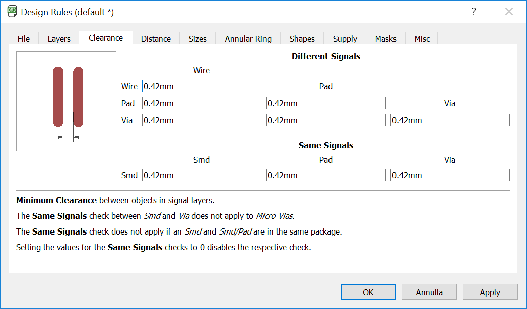
Figure 5. Design Rules
To place the routes I used a 12,5mil Grid, like a quarter of the pitch of the ATtiny44.

Figure 6. Grid
I used 16mil Width and Wire bend style 0 setting to make the Route.
Normally this style it is not the better solution for electrical reasons,
but it is ideal for the milling machine.
Before finding my preferred location for the components and their connections I had to make various tries to
avoid the routes overlapping, this was the most complicated and longest phase.
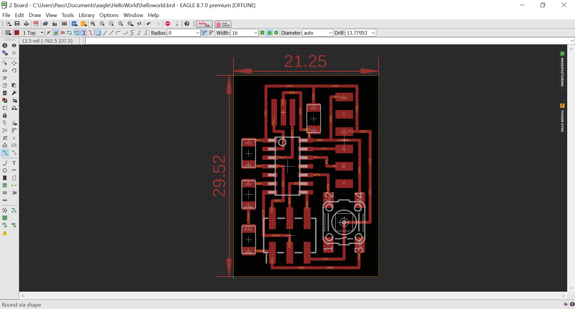
Figure 7. Board
Export
To export only the routes I have hidden all layers except Top and Dimension.
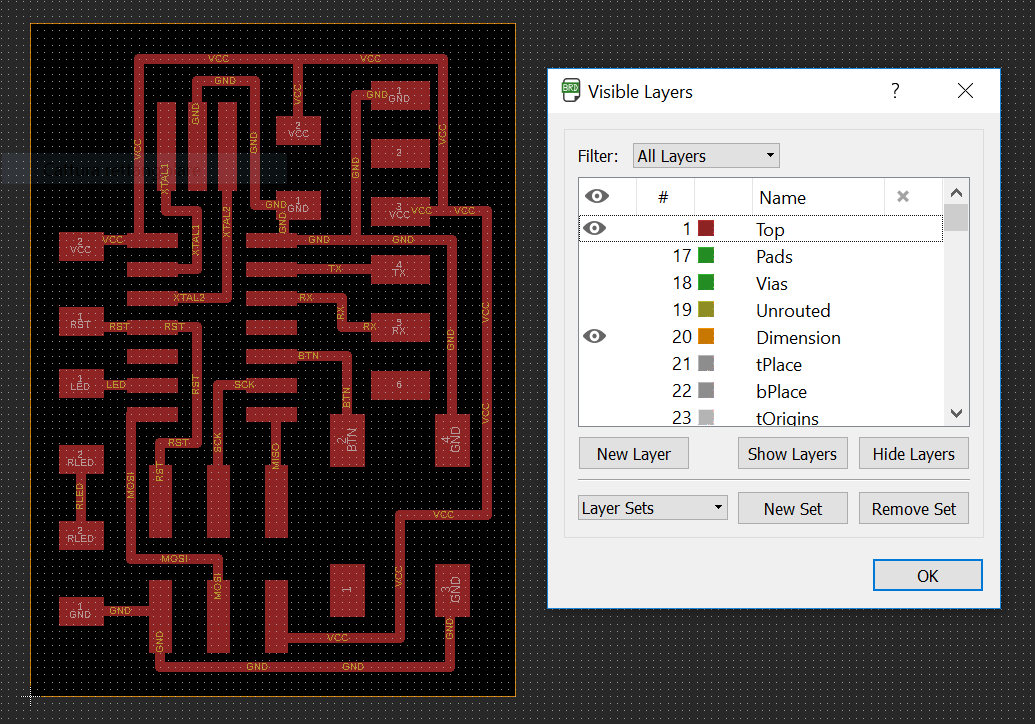
Figure 8. Visible Layers
By File -> Export -> Image I set Monochrome and 1000 dpi to export a white and black png file.
To export only the routes I have hidden all layers except Top and Dimension.
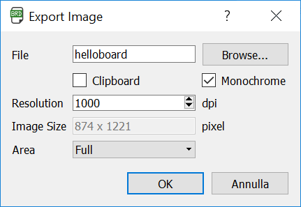
Figure 9. Export Image
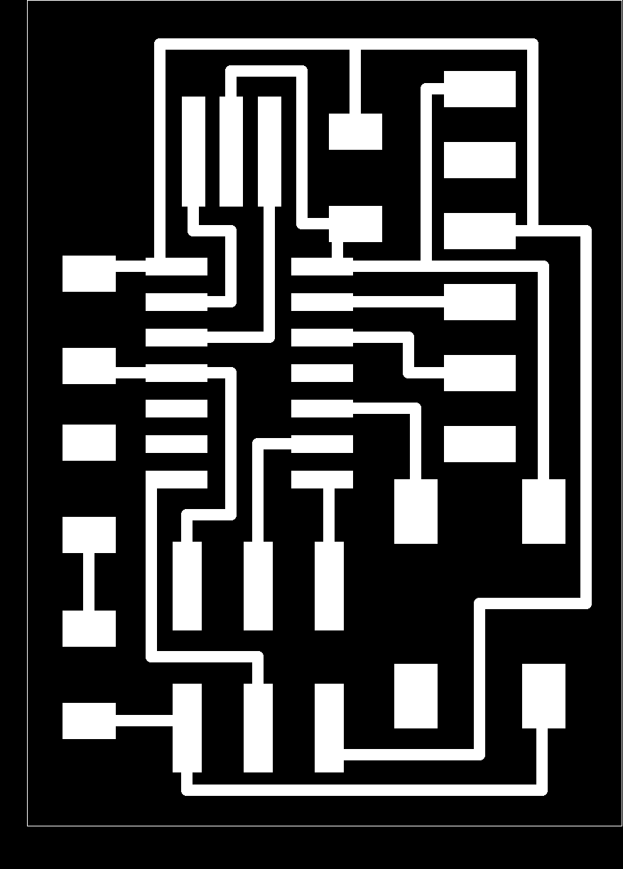
Figure 10. The export result
Preparation
Finally in GIMP I adjusted the file and drew the outline. The generated files are ready to be imported into Fab Modules.

Figure 11. Traces

Figure 12. Traces
Fabrication
I used the same FabTinyISP process to make it. This is the result after cleaning:
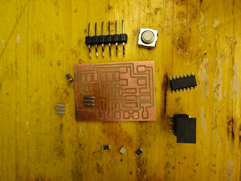
Figure 13. Board with the components
BOM
- ATtiny44 SOIC
- Resonator 8.00MHz
- Capacitor 1206 1uF
- Header 1x6
- Header 2x3
- Resistor 1206 10k
- Resistor 1206 220
- Momentary button
And this is the final result:
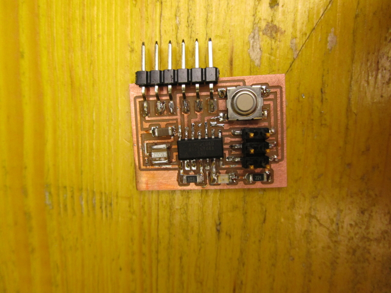
Figure 13. Board populated
Testing
To test it I uploaded with my FabTinyISP a sketch written by me on Arduino IDE. I used a FTDI cable to power my board.
Requirements
First I downloaded Arduino IDE from the official
website and installed it.
In File -> Prefences I clicked on the window icon to the right of
Additional Boards Manager URLs, there I pasted https://raw.githubusercontent.com/damellis/attiny/ide-1.6.x-boards-manager/package_damellis_attiny_index.json.
I found this link by searching ATtiny in the page that opens by clicking on Click for a list of
unofficial boards support URLs in same window.
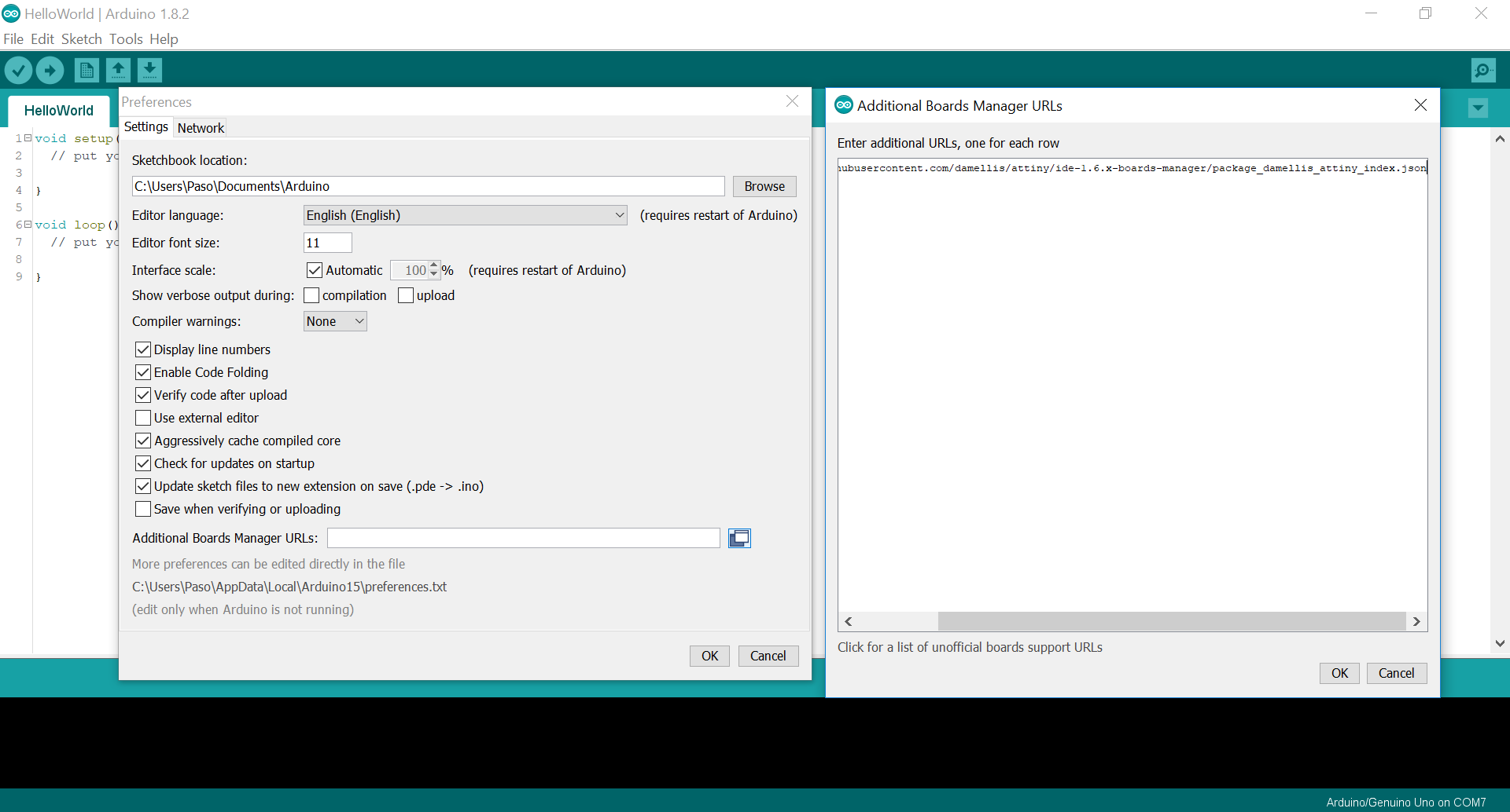
Figure 12. Unofficial boards support settings
To install the board support in Tools -> Board -> Boards Manager... I searched attiny and installed it.
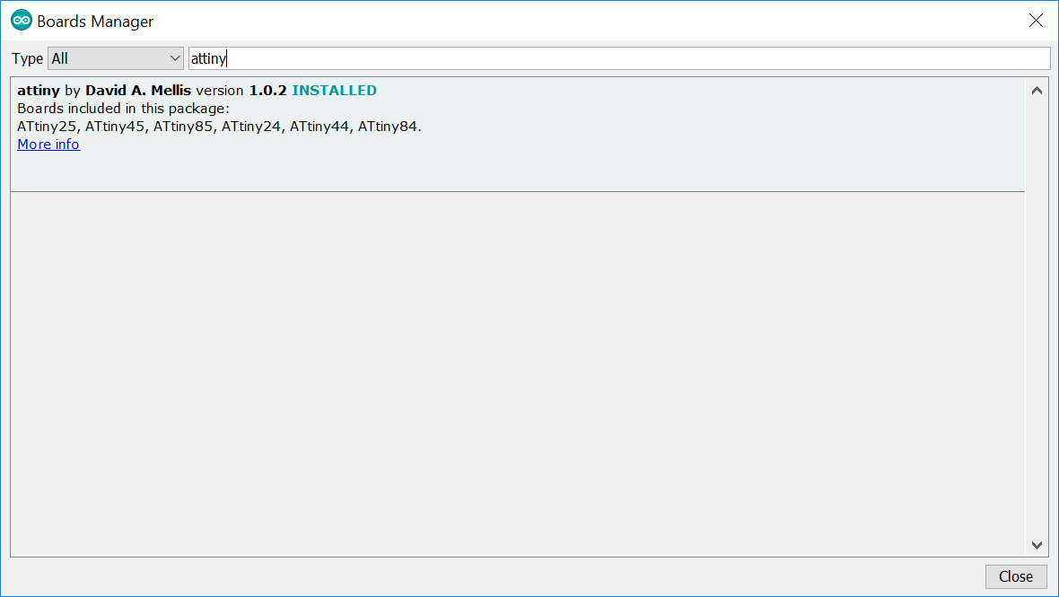
Figure 13. Boards Manager
Sketch
I wrote a sketch that blinks the led at a frequency of 10Hz only when the button is not pressed.
download HelloWorld 692 kB (.ino)#define LED 7 // define the led pin
#define BTN 3 // define the button pin
// run only once
void setup() {
// set the led pin like output
pinMode(LED, OUTPUT);
// set the button pin like input
// pinMode(BTN, INPUT); // if you have an external PULL-UP or PULL-DOWN move '//' at start of the line below
pinMode(BTN, INPUT_PULLUP);
}
// run in loop
void loop() {
if (digitalRead(BTN)) { // run only if the button is not pressed (with PULL-UP)
digitalWrite(LED, HIGH); // turn on the led
delay(50); // wait 50 millisecond
digitalWrite(LED, LOW); // turn off the led
delay(50); // wait 50 millisecond
} // END if
delay(1); // wait 1 millisecond
}The upload process:
This is the verbose output during upload:
avrdude: Version 6.3, compiled on Jan 17 2017 at 12:00:53
         Copyright (c) 2000-2005 Brian Dean, http://www.bdmicro.com/
         Copyright (c) 2007-2014 Joerg Wunsch

         System wide configuration file is "C:\Users\Paso\AppData\Local\Arduino15\packages\arduino\tools\avrdude\6.3.0-arduino9/etc/avrdude.conf"

         Using Port                    : usb
         Using Programmer              : usbtiny
avrdude: usbdev_open(): Found USBtinyISP, bus:device: bus-0:\\.\libusb0-0001--0x1781-0x0c9f
         AVR Part                      : ATtiny44
         Chip Erase delay              : 4500 us
         PAGEL                         : P00
         BS2                           : P00
         RESET disposition             : possible i/o
         RETRY pulse                   : SCK
         serial program mode           : yes
         parallel program mode         : yes
         Timeout                       : 200
         StabDelay                     : 100
         CmdexeDelay                   : 25
         SyncLoops                     : 32
         ByteDelay                     : 0
         PollIndex                     : 3
         PollValue                     : 0x53
         Memory Detail                 :

                                  Block Poll               Page                       Polled
           Memory Type Mode Delay Size  Indx Paged  Size   Size #Pages MinW  MaxW   ReadBack
           ----------- ---- ----- ----- ---- ------ ------ ---- ------ ----- ----- ---------
           eeprom        65     6     4    0 no        256    4      0  4000  4500 0xff 0xff
           flash         65     6    32    0 yes      4096   64     64  4500  4500 0xff 0xff
           signature      0     0     0    0 no          3    0      0     0     0 0x00 0x00
           lock           0     0     0    0 no          1    0      0  9000  9000 0x00 0x00
           lfuse          0     0     0    0 no          1    0      0  9000  9000 0x00 0x00
           hfuse          0     0     0    0 no          1    0      0  9000  9000 0x00 0x00
           efuse          0     0     0    0 no          1    0      0  9000  9000 0x00 0x00
           calibration    0     0     0    0 no          1    0      0     0     0 0x00 0x00

         Programmer Type : USBtiny
         Description     : USBtiny simple USB programmer, http://www.ladyada.net/make/usbtinyisp/
avrdude: programmer operation not supported

avrdude: Using SCK period of 10 usec
avrdude: AVR device initialized and ready to accept instructions

Reading | ################################################## | 100% 0.01s

avrdude: Device signature = 0x1e9207 (probably t44)
avrdude: NOTE: "flash" memory has been specified, an erase cycle will be performed
         To disable this feature, specify the -D option.
avrdude: erasing chip
avrdude: Using SCK period of 10 usec
avrdude: reading input file "C:\Users\Paso\AppData\Local\Temp\arduino_build_203369/HelloWorld.ino.hex"
avrdude: writing flash (894 bytes):

Writing | ################################################## | 100% 1.27s

avrdude: 894 bytes of flash written
avrdude: verifying flash memory against C:\Users\Paso\AppData\Local\Temp\arduino_build_203369/HelloWorld.ino.hex:
avrdude: load data flash data from input file C:\Users\Paso\AppData\Local\Temp\arduino_build_203369/HelloWorld.ino.hex:
avrdude: input file C:\Users\Paso\AppData\Local\Temp\arduino_build_203369/HelloWorld.ino.hex contains 894 bytes
avrdude: reading on-chip flash data:

Reading | ################################################## | 100% 1.82s

avrdude: verifying ...
avrdude: 894 bytes of flash verified

avrdude done.  Thank you.
It work!
Group Assignment
More info on the Opendot group assignment page.