- Assignment 03
Computer-Controlled Cutting
This week is dedicated to the use of machines working in 2D.
Vinyl Cutting
The tools that i used are Solidworks to design, Silhouette Studio like CAM and my Silhouette Cameo.
Design
I designed a parametric photo box using Solidworks. I have parameterized so that I can easily change the dimensions of the box.
download Photobox 64,3 kB (.sldprt)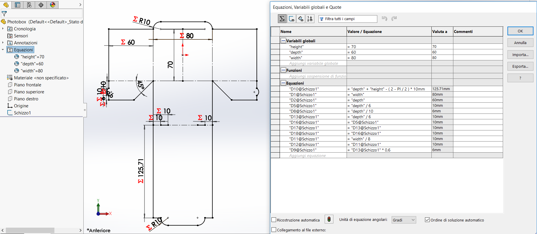
Figure 01. Drawing in Solidworks
For the next step I exported the sketch in dxf.
download Photobox 27,6 kB (.dxf)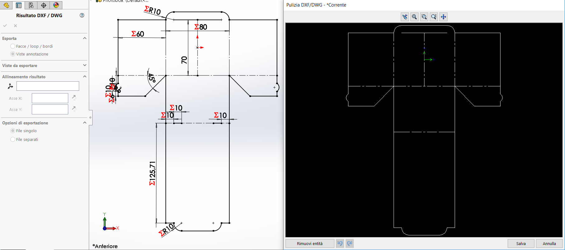
Figure 02. Export by Solidworks
CAM
I imported the dxf in Silhouette Studio, set A4 landscape as paper and converted the dashed lines into continuous lines.
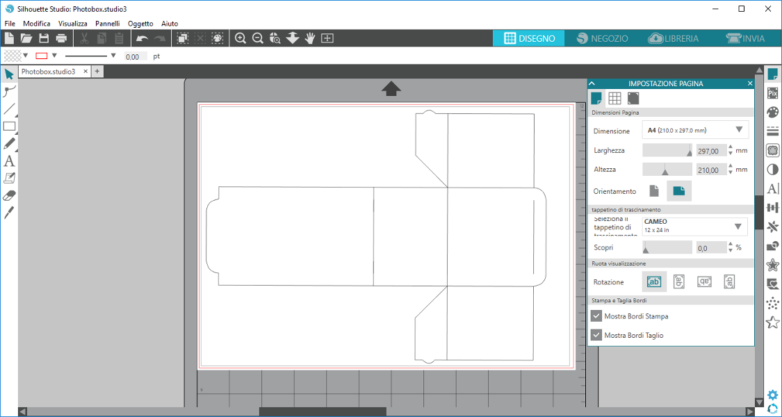
Figure 03. File after fixing
The machine had mounted two heads, one for the cut and one pen. So I set the red lines for cutting and the blue lines for drawing.
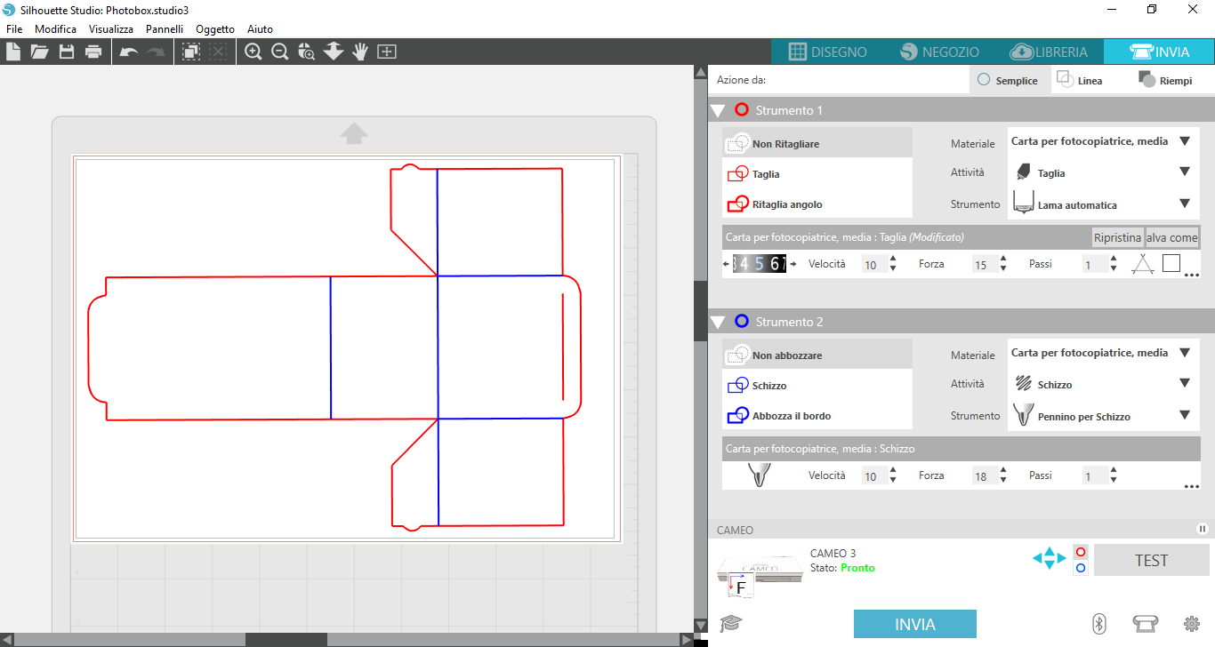
Figure 04. All settings
Cutting
The machine is equipped with an adhesive sheet on which I affixed the paper sheet to cut (A4, 200
g/m2).
Afterward I placed it against the wheels of the machine. Before proceeding I moved the right-hand wheel for
adapt it to the size of the adhesive sheet,
the difference between Figure 5 and Figure 6 can be seen.
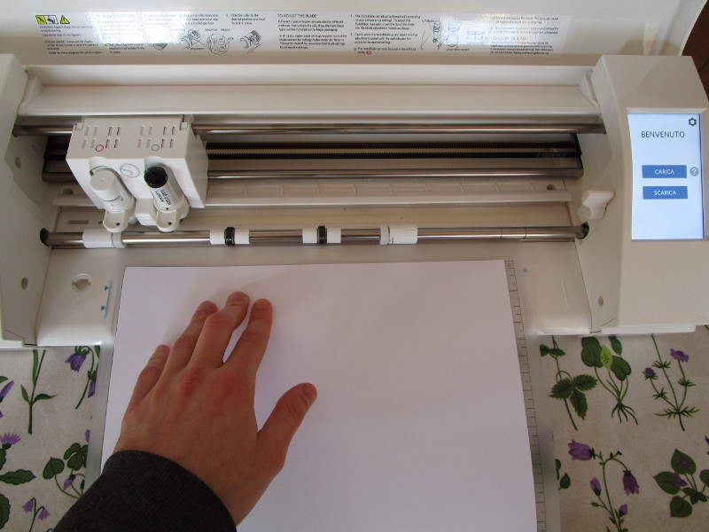
Figure 05.
To insert the sheets I pressed charge (CARICA) on the screen. Now everything is ready for cutting.
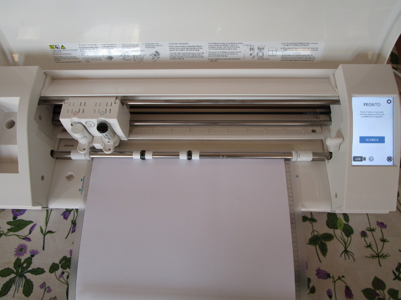
Figure 06. Ready to cut
From the screen visible in Figure 4 I pressed send (INVIA). The cut was successful.
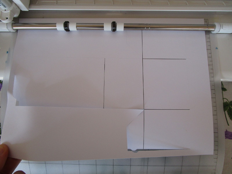
Figure 07. The cut was successful
This is the final result after I removed everything
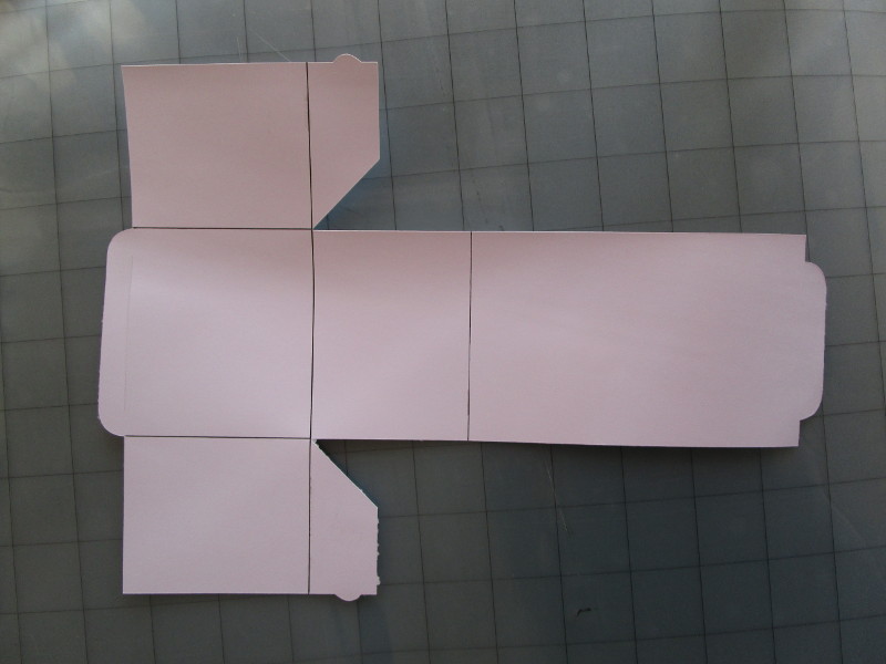
Figure 08. The result
Assembly
Following the pen lines I bent the sheet to give it the desired shape.
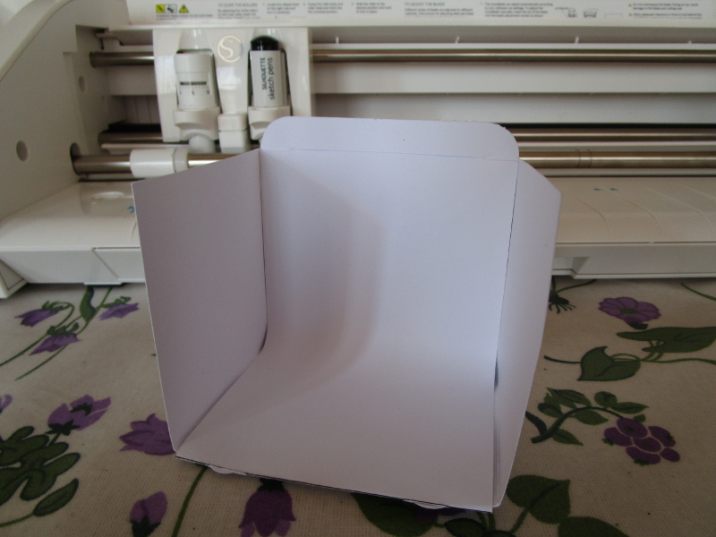
Figure 09. The final result
And this is a photo test with a miniature painted by me.
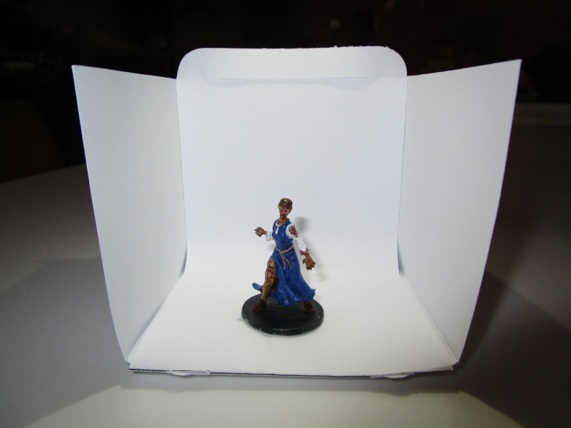
Figure 10. The original photo
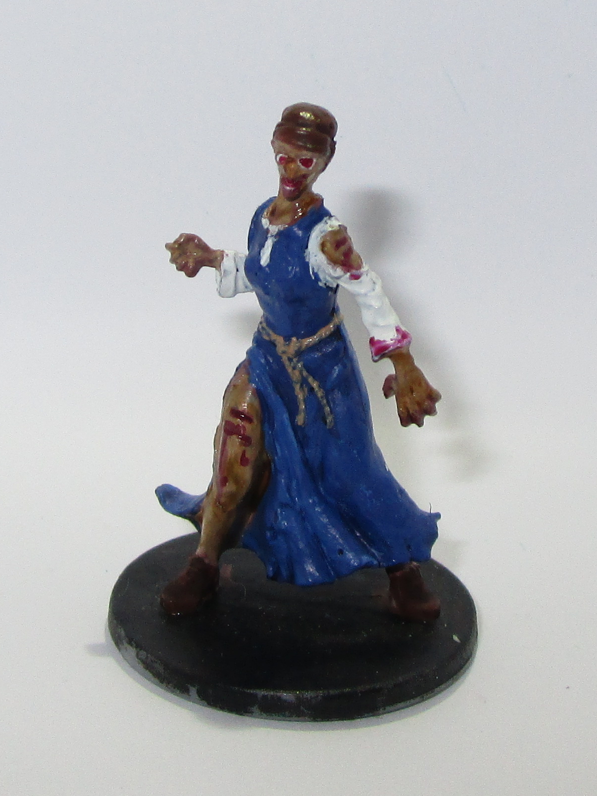
Figure 11. The cropped photo
Other
Using the same process, but without using the adhesive sheet, I also made a vinyl sticker using a file made last week with Inkscape.
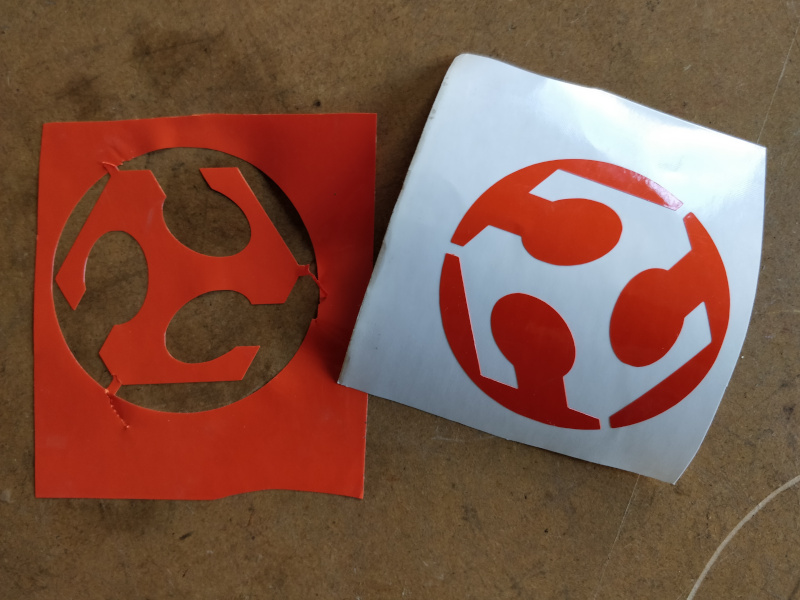
Figure 12. The Fabacademy sticker logo.
Figure 13. The sticker on my PC.
Laser Cutting
For lasercutting I decided to design a Rubik's Snake to cut with a SpiritGLS by GCC.
Design
Also with Solidworks I designed the project and parameterized it with the thickness of panel "t" and the tolerance for the joint "i".
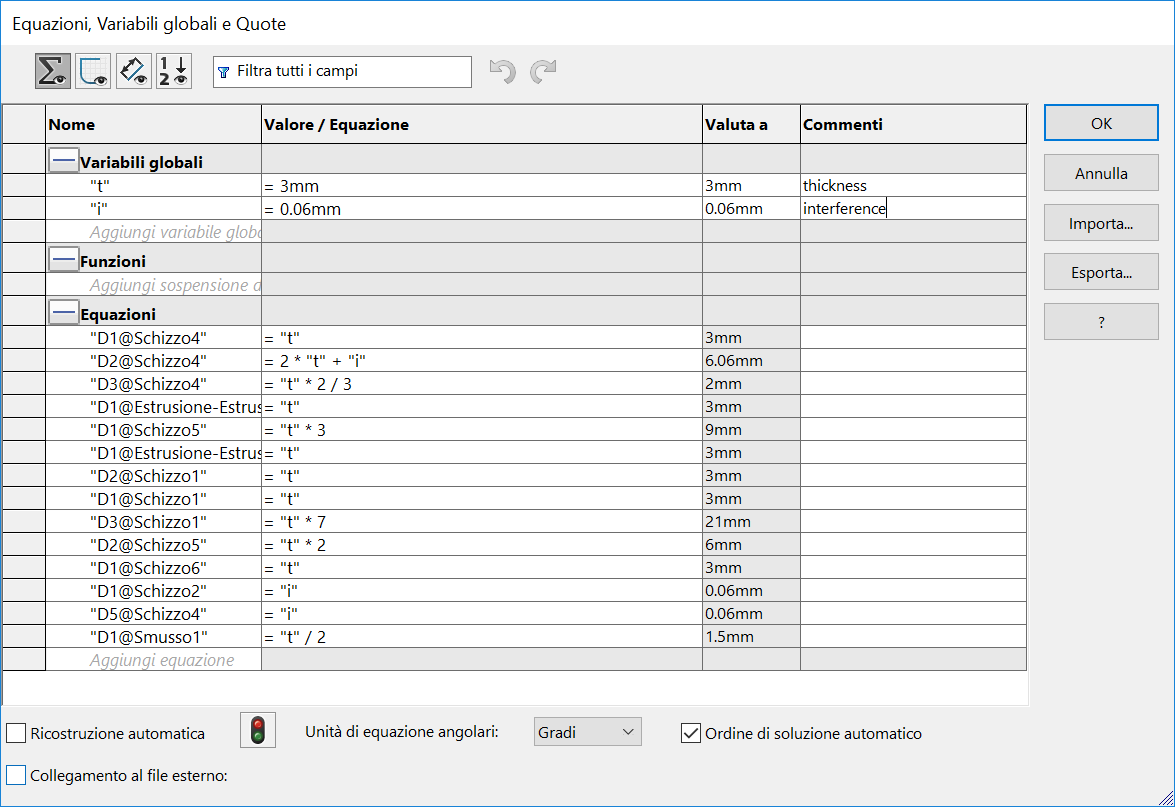
Figure 14. Equations
The design is unique and divided into 4 different bodies, two of them, which I mirrored, are repeated twice for each segment of the snake.
download RubikSnake 347 KB (.SLDPRT)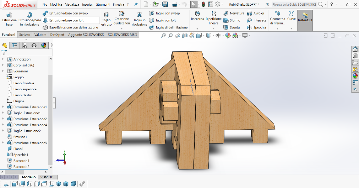
Figure 15. Drawing in Solidworks
Separately I exported the faces in DXF and with Rhinoceros I made the table and add a 0.1mm
kerf with Offset command. Since the program I used later to send the file to the lasercut
is always Rhinoceros I saved in its native 3DM format.
For completeness also attached the DXF.
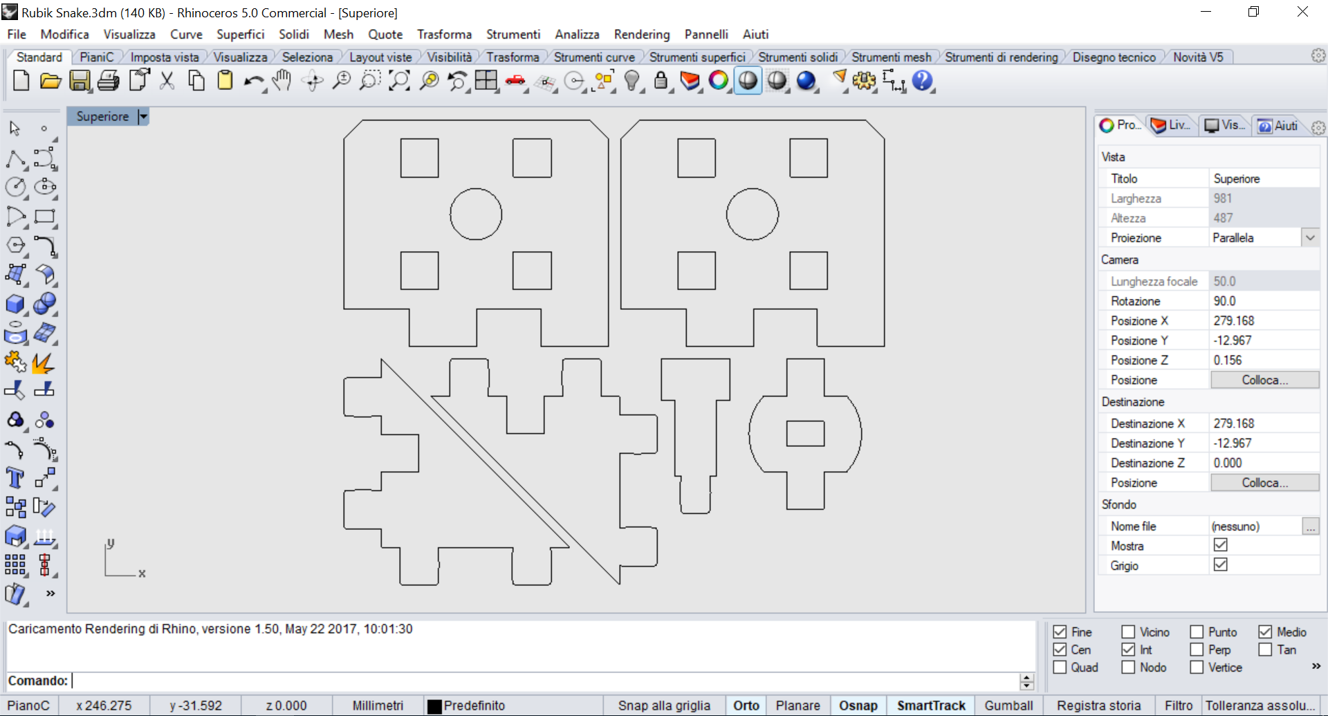
Figure 16. Table in Rhinoceros
download RubikSnake 140 KB (.3dm) download RubikSnake 190 KB (.dxf)CAM
On the computer connected to the lasercut I opened the 3DM file, cloned the segment a few times and in the Properties I made sure that they were all defined as By Layers to prevent lines from getting thick.
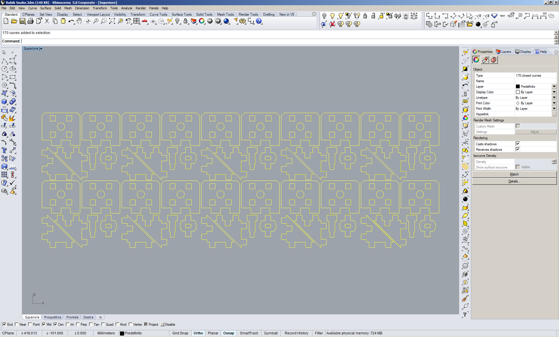
Figure 17. Ready to cut in Rhinoceros
The program sees the lasercut as any printer so I did File -> Print to open the CAM interface.
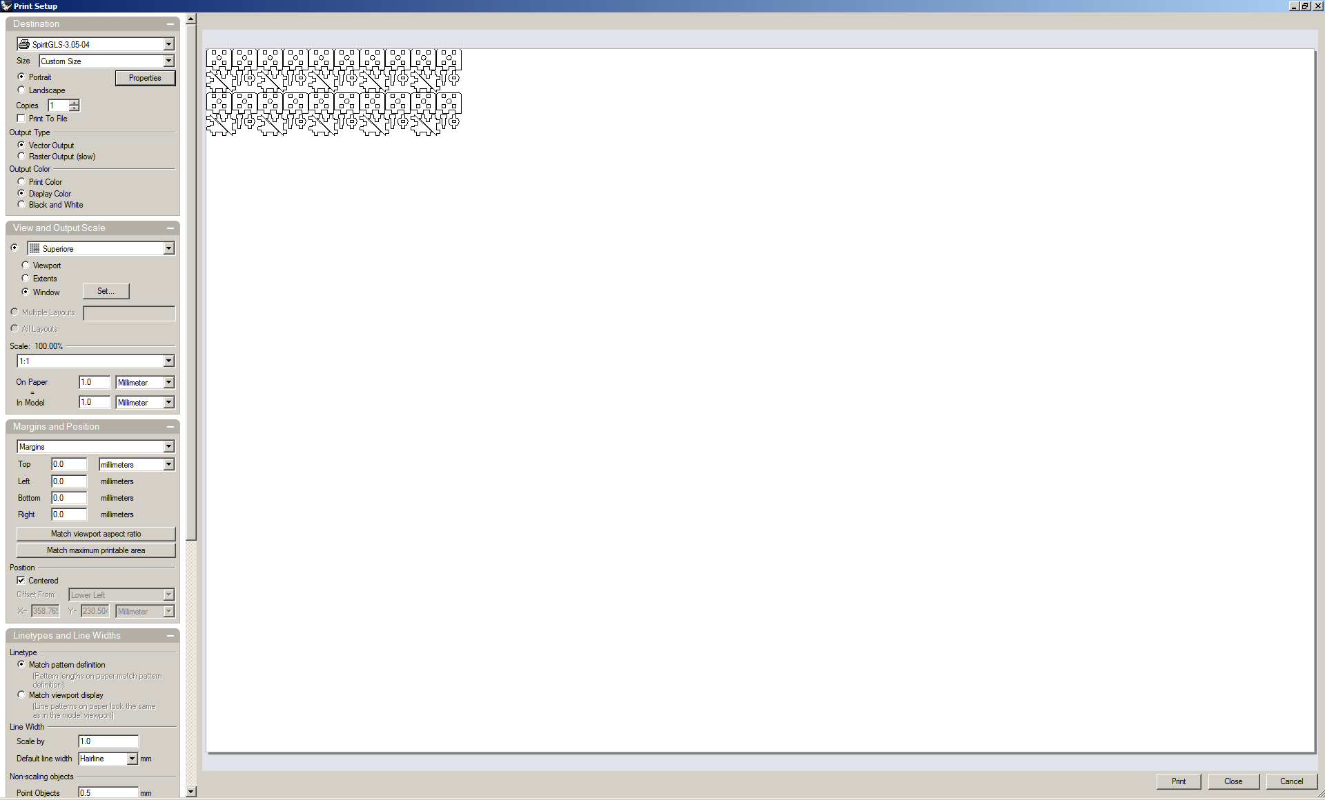
Figure 18. The print screen
In View and Output Scale I clicked Set... to set the virtual workspace. Then I opened the Properties to set the cutting parameters.
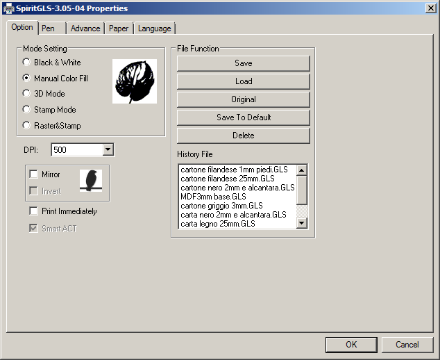
Figure 19. Option
In Pen I reduced the cutting speed to 2.0 mm/s.
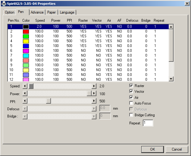
Figure 20. Pen
In Advance I set the Position Mode to Relative to start cutting from the top left corner of the drawing starting from the laser position in the machine.
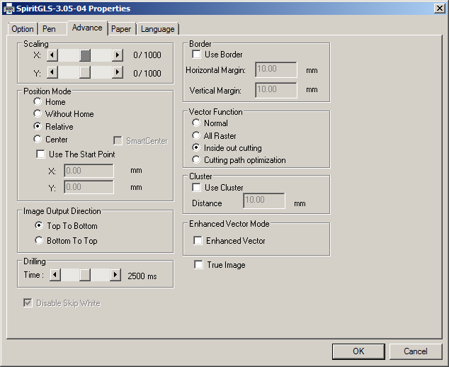
Figure 21. Advance
Therefore I clicked on OK and Print to send the file to the lasercutter.Cutting
The lasercutter is a SpiritGLS by GCC with a 960x610 cutting area. I placed a 3mm MDF panel under the machine head and from the control panel I pressed Auto Focus to adapt the table top to the thickness of the material to be cut.
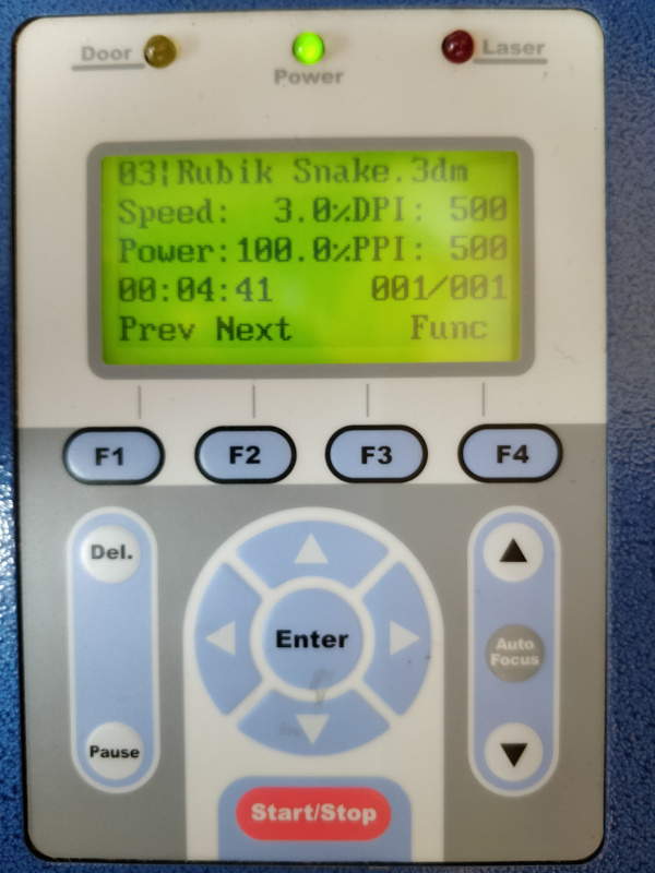
Figure 22. The controller
The head from which the laser comes out can be moved by hand, so I placed it in the top right corner for panel and, after closing the protective cover, I pressed on Start.
You can see the laser cutting through the protective cover.
This is the result once the machine is finished.
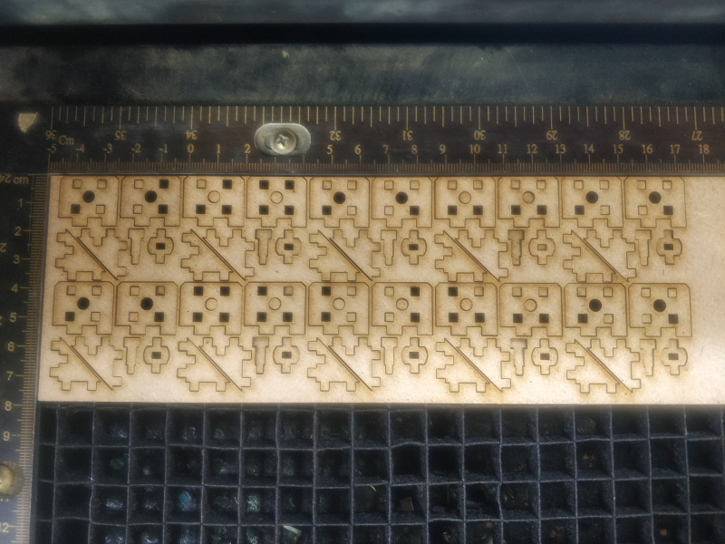
Figure 23. After cutting
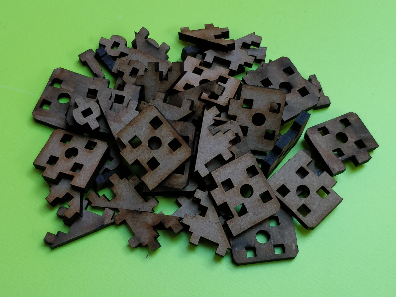
Figure 24. Some pieces
Assembly
This is the assembly sequence I followed.
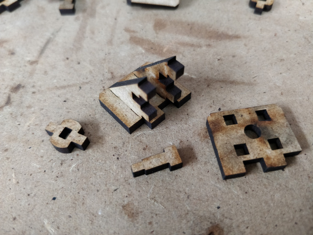
Figure 25. Step 1
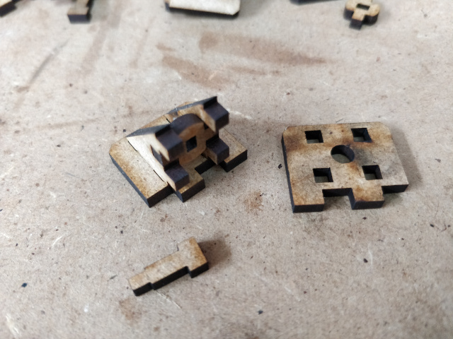
Figure 26. Step 2
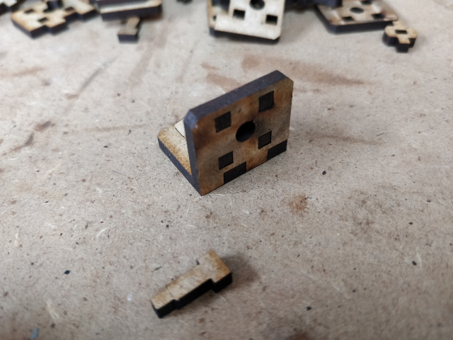
Figure 27. Step 3
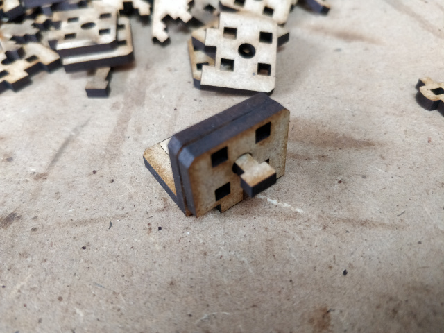
Figure 28. Step 4
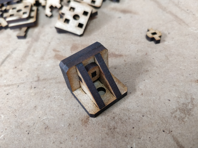
Figure 30. Step 5
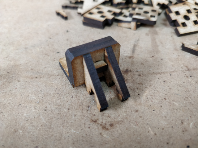
Figure 32. Step 6
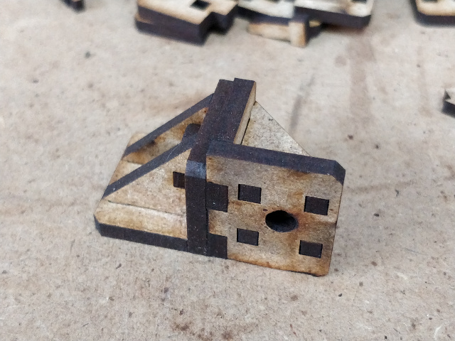
Figure 33. Step 7
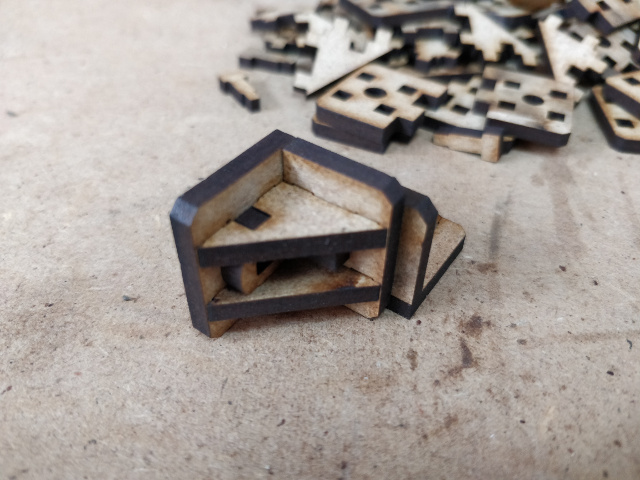
Figure 34. Two joined segments
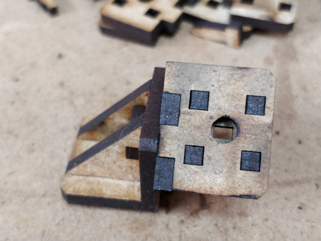
Figure 35. Two joined segments
All the pieces fitted perfectly without the use of glue, but for safety I put some vinyl on the outer sides.
This is my Rubik's snake with 14 segments!
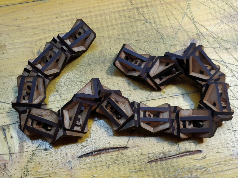
Figure 36. My Rubik's snake
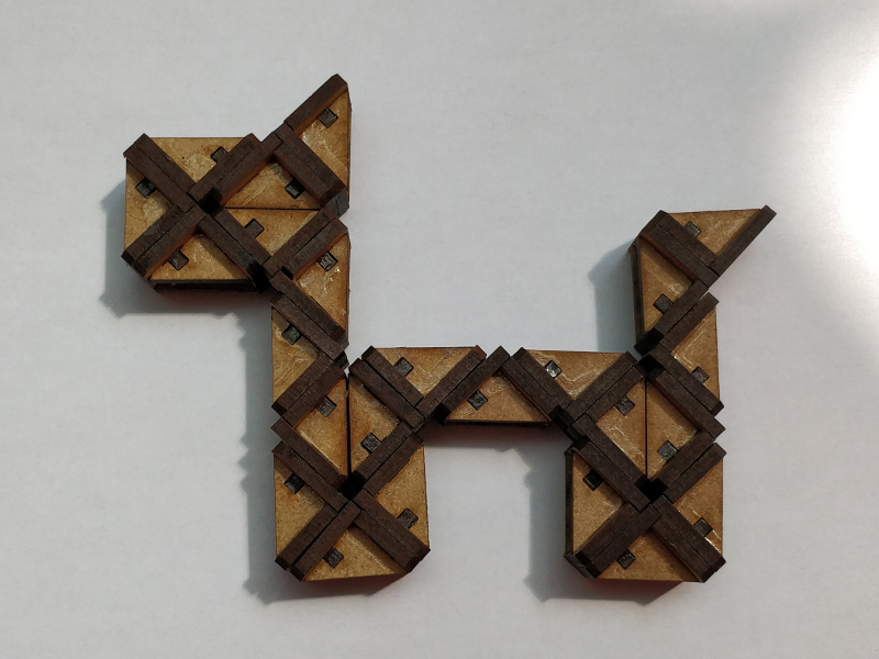
Figure 37. The dog figure
Group Assignment
More info on the Opendot group assignment page.