- Assignment 02
Computer-Aided Design
Know how to model with CADs is essential for the coming weeks, in this I tried some 2D and 3D software.
3D CAD
I evaluated 3 different parametric software: Solidworks (that I have already used), Fusion 360 and OnShape.
Solidworks
Solidworks is the most powerful (and expensive) 3D CAD, to test it I designed a parametric box conceived for
laser cutter. It is composed of three pieces repeated 2 times each: Bottom, Front and
Side.
The shapes are simple, but I worked a lot on parameterization. I make dimensions.txt file to
store the 5 parameters:
"thickness"= 3mm'panel thickness
"tooth" = 2'tooth length ratio
"width" = 100mm'internal width
"depth" = 80mm'internal depth
"height"= 60mm'internal height
Bottom
Bottom part is composed by a rectangle with the sides as long as width and depth variables.
After I added the tooth, the length is calculated so that it is as close as possible to `"thickness" *
"tooth"`. Spaces and tooth have equal length.
The complete formula (compatible with any spreadsheet) is:
` "number_of_tooth" = round( "width" / (2 * "thickness" * "tooth") + 1/2) `
` "length_of_tooth" = "width" / (2 * "number_of_tooth" -1) `
At the end I added the corners.
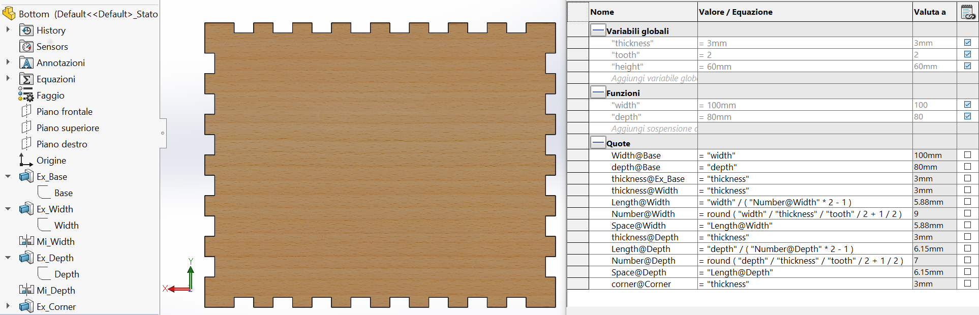
Figure 1. Bottom (and Top) part of the box
Front
To make Front part I copied Bottom part, removed the corners, replaced depth with height
and used Width sketch to cut a rectangle previously extruded (Ex_Width in figure).
Suspending Mi_Width function I can remove the top tooth to make boxes without cover.
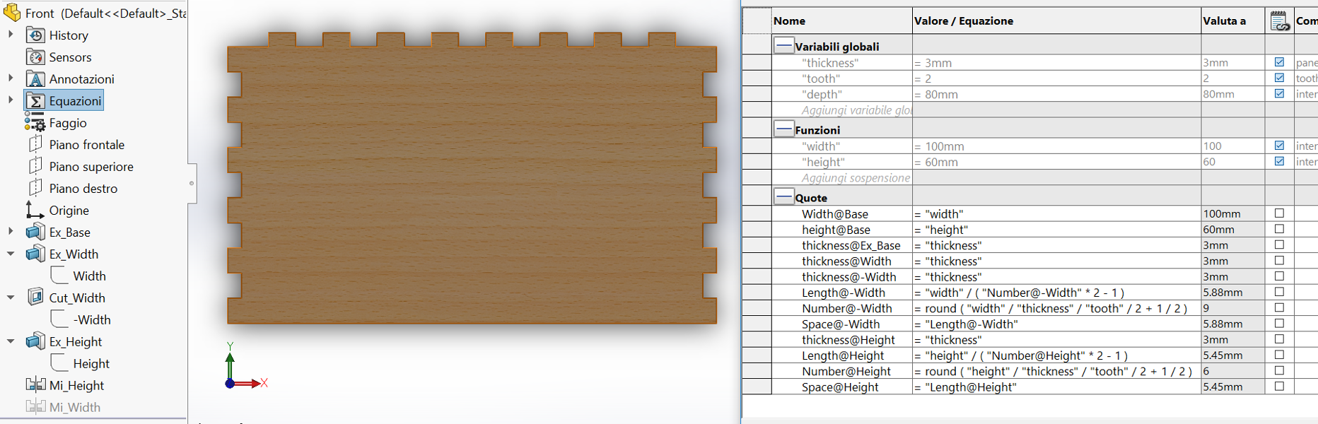
Figure 2. Front (and Back) side of the box
Side
This time I copied Front part, replaced width with depth and repeated previous process with height.
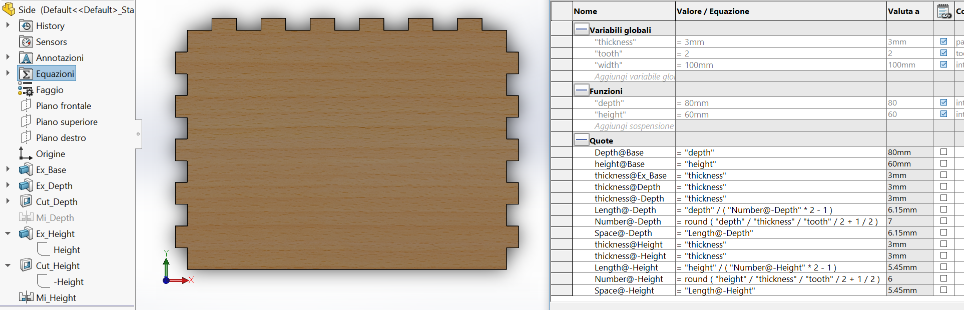
Figure 3. Side (Left and Right) part of the box
Box assembly
To see if I made everything correctly I assembled the box.
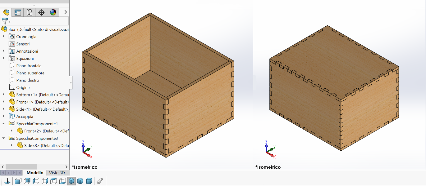
Figure 4. Box assembled without and with top part
download Box 1,30 MB (.zip)
Fusion 360
With Fusion 360 I have not drawn anything worthy of note, but I tested an awesome plugin to generate a Kerf (laser cut width) compensated DXF file.
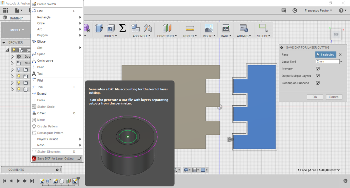
Figure 5. DXF for Laser plugin
OnShape
Onshape is an online 3D CAD with same geometric modeling kernel (Parasolid) of Solidworks, indeed it is very similar to it. Free subscription only allows public data, but don't have other restriction. It is more intuitive than the other two and the main functions are more accessible.
To test it I design a stamp.
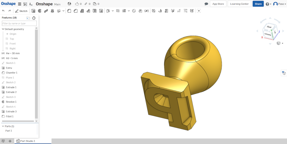
Figure 6. Stamp
2D Software
Also in this case I evaluated 3 different 2D software, but very different: Rhinoceros, Inkscape and GIMP.
Rhinoceros
Rhinoceros is useful to view DXF file generated with other programs and is also convenient for manual nesting. It is also useful to make the kerf with Offset command.
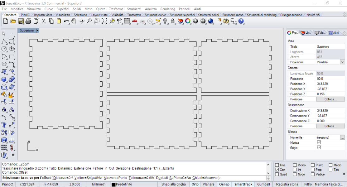
Figure 7. Manual nesting and offset command
download nesting 250 kB (.dxf)Inkscape
Inkscape is an Open Source vector graphics editor, with capabilities similar to Illustrator and CorelDraw.
I have tested it to trace bitmaps. I imported a .jpg by drag-n-drop and I opened the Trace Bitmap window available in Path and I increased the Threshold up to 0,6 to view the image correctly.
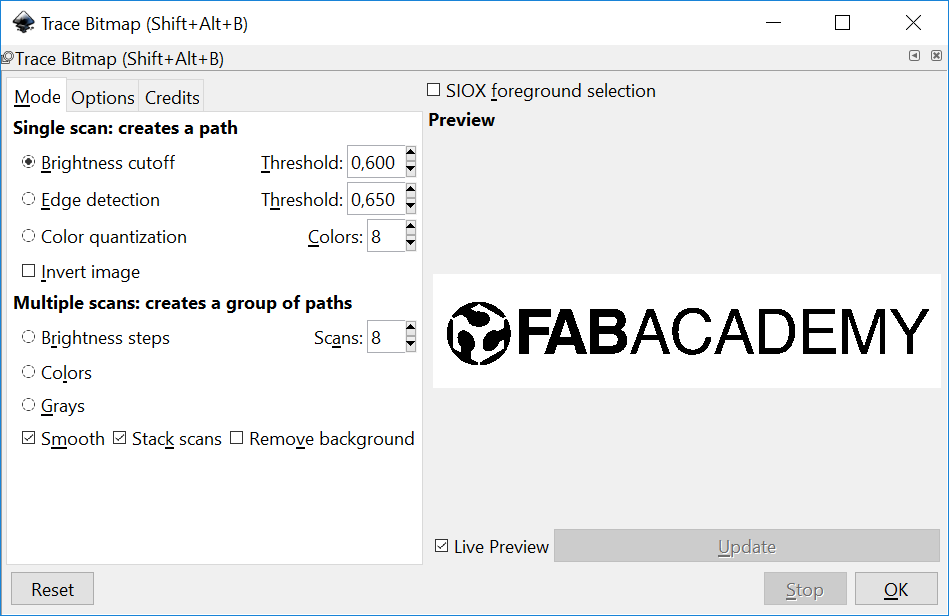
Figure 8. Trace Bitmap window
After clicking on OK I closed the window. To see difference between bitmap and vector I changed view by means of View -> Display mode -> Outline

Figure 9. Normal view
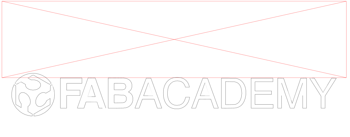
Figure 10. Outline view
download outline 270 kB (.svg)
download outline 73,6 kB (.dxf)
GIMP
GIMP is a free program for such photo retouching, image composition and image authoring.
I used it to crop all images in my site by means of Crop tool command.
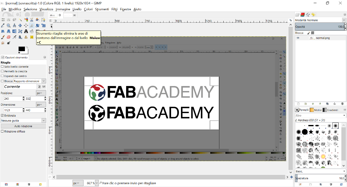
Figure 11. Crop tool command
Final project
I also designed a final project sketch with Solidworks.
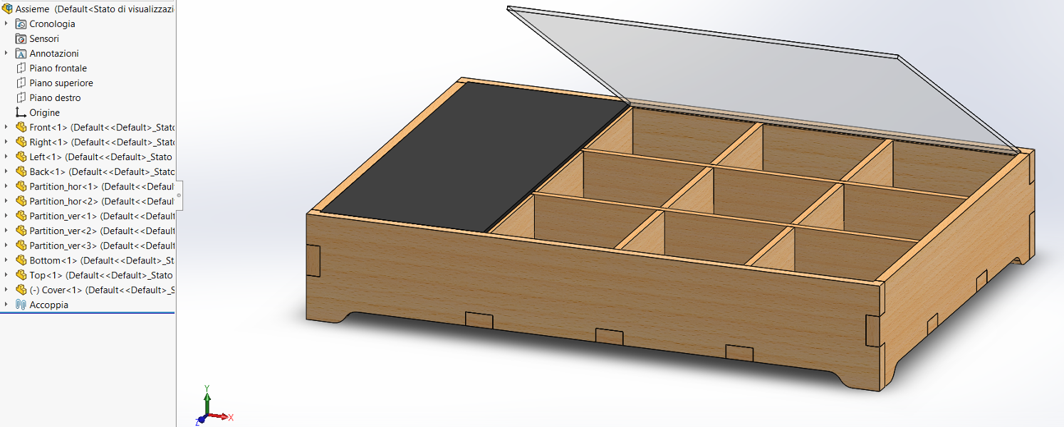
Figure 12. Final project 3D sketch
download Assembly 104 kB (.stl)