Assignment
- Make something big
Designing in Solidworks
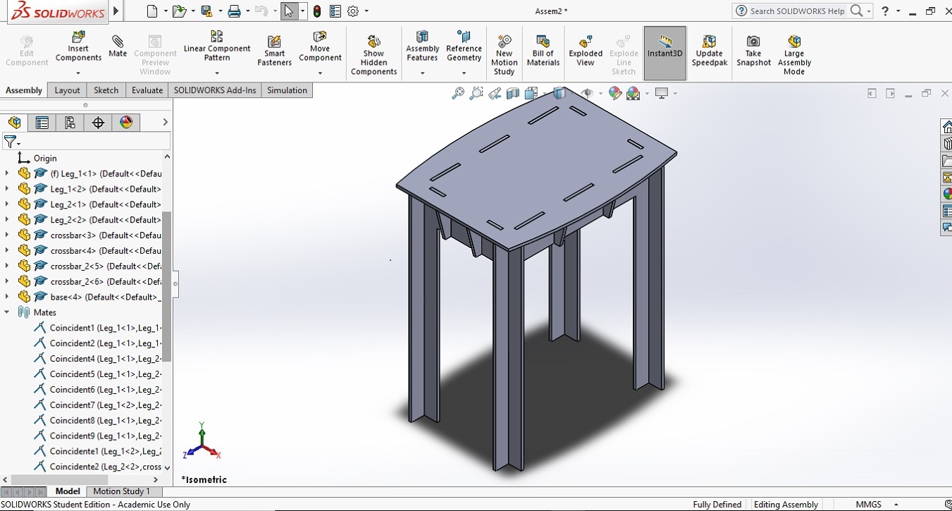
For this assignment I wanted to design and build a rectangular table which doesn’t require any nail or glue to be assembly. With that idea in mind I designed a table in 9 parts (1 table top, 4 legs and 4 supports for the top). The idea is that the table works as a press fit model. The parts and the assembly can be seen in Figures 1 to 6, as well as a description of each part.
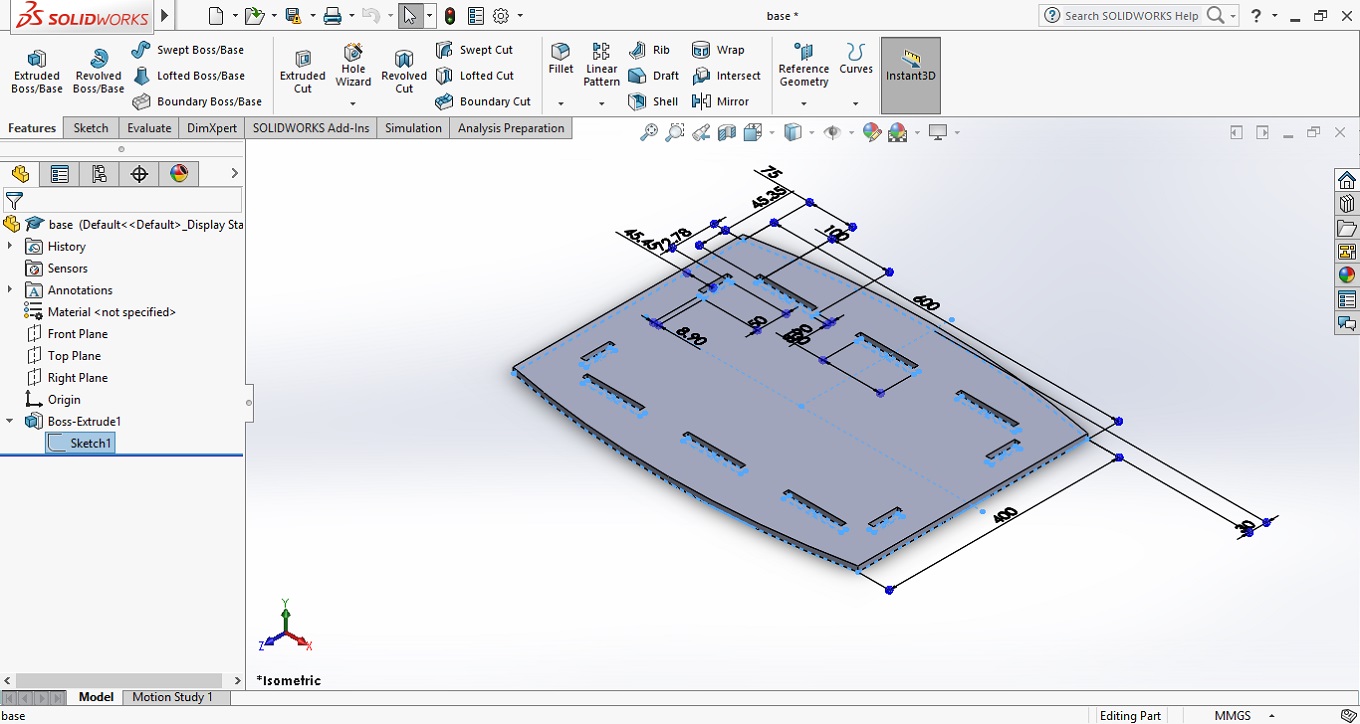
The table top consists in a rectangular shape with the long sides rounded. The dimensions are
600 mm x 400 mm. The top has 8 slots (6 in the long sides and 4 in the short sides) which will have the function to keep this part fix.
The dimensions of the slots are 100 mm x 8.90 mm, in the long sides and 50 mm x 8.9 mm in the short sides. The 8.90 mm dimension corresponds
to the thickness of the wood that was used minus 0.1 mm. The 0.1 mm less was used to give the table top more stability.
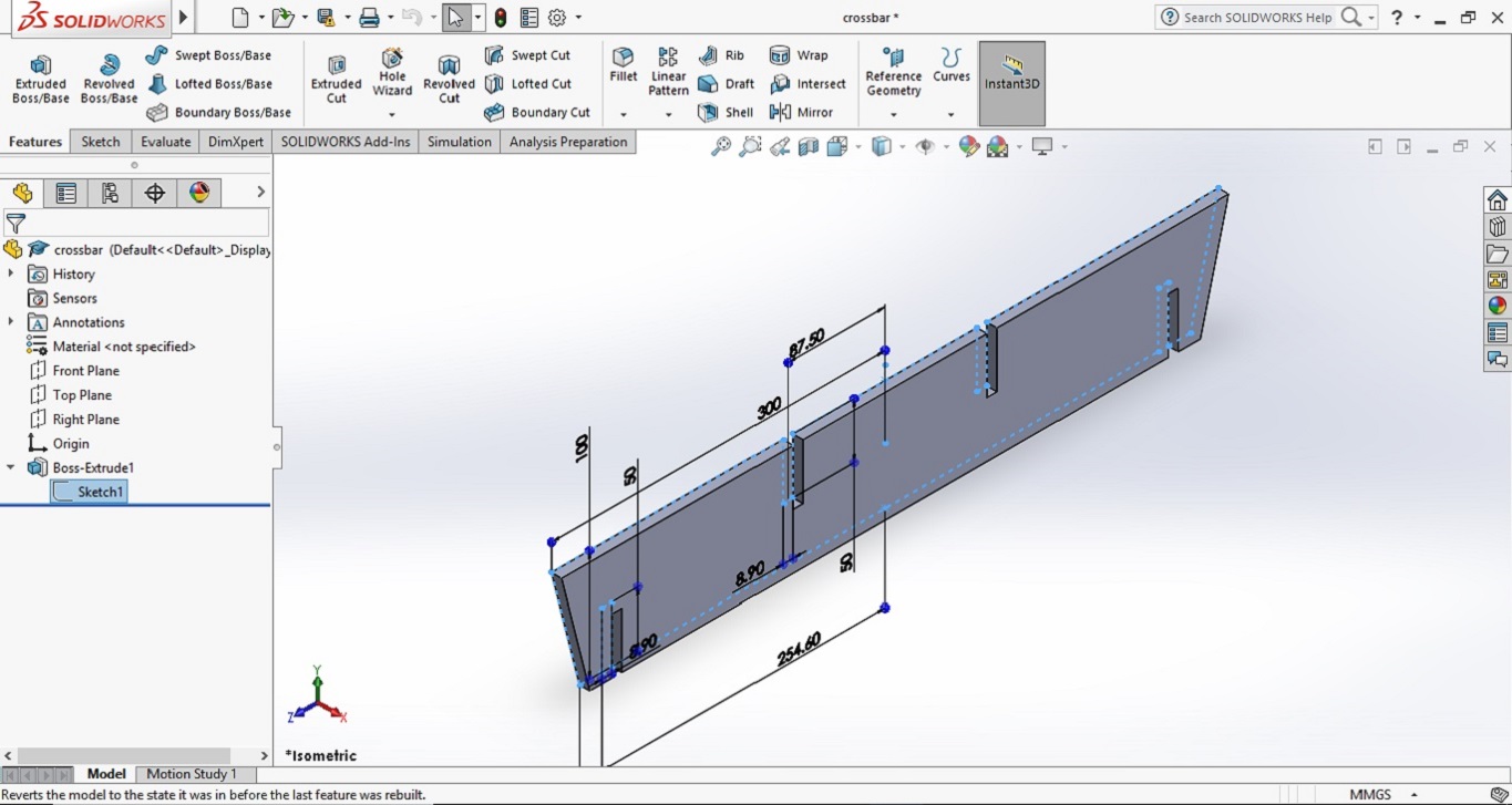
The table has four crossbars,
the one in the Figure 2 runs along the long side. As is seen in the figure has a trapezoidal shape.
The crossbar has 4 slots: the ones in the extremes will fit in the short legs (Figure 5) and the one in the
middle will fit in the short crossbars (Figure 3). This crossbar must be done twice.
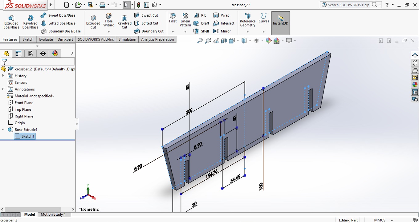
This crossbar which runs along the short side of the rectangular
table also has four slots but this time all facing down. The slots in the extremes will fi tin the long legs (Figure 4)
and the slots in the middle will fit in the long crossbars (Figure 2). This crossbar also must be done twice.
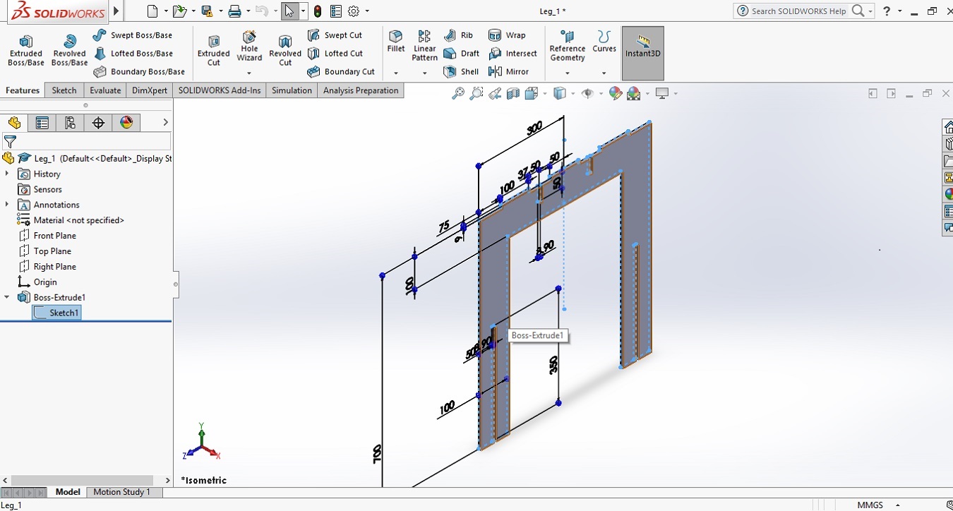
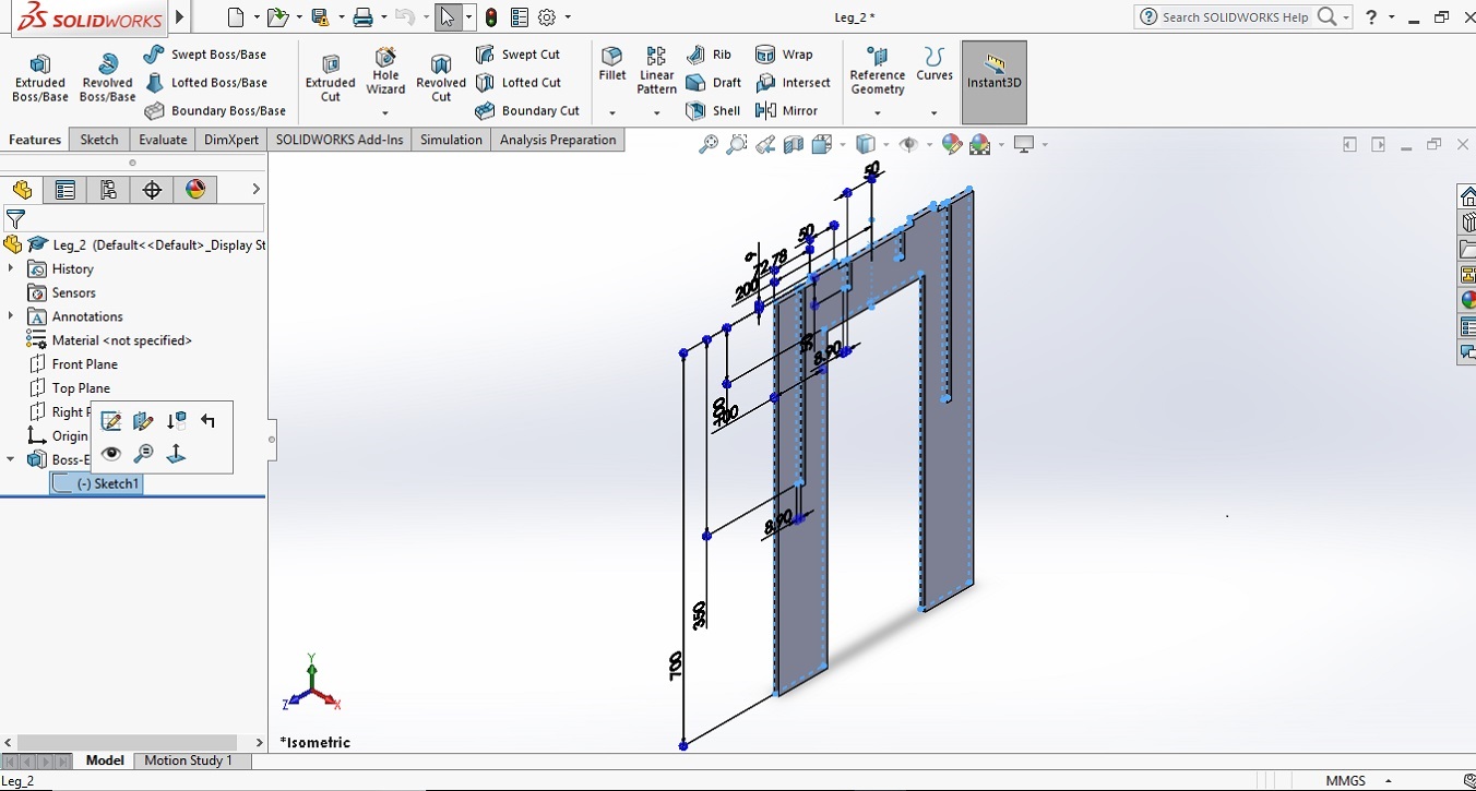
The legs (Figure 4 and 5) have shapes in the upper side
which must fit in the table top slots (Figure 1); three in the long leg and two in the short ones. Also, each one
of the legs has four slots, two small ones in the middle (where the crossbars must fit) and two long slots. The leg for
the long side (Figure 4) has the slots facing down and the leg for the short side has these slots facing up. The idea is
that the two long leg fit the two short legs and form a cross (Figure 6).
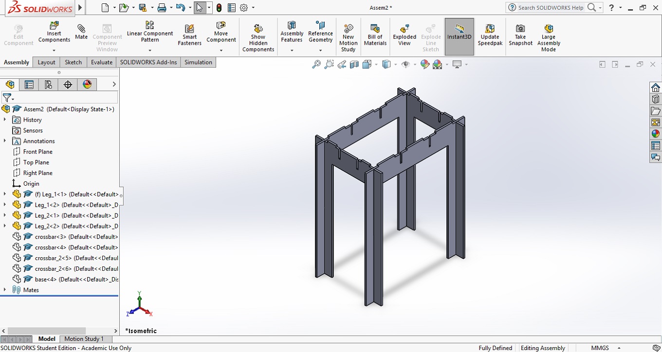
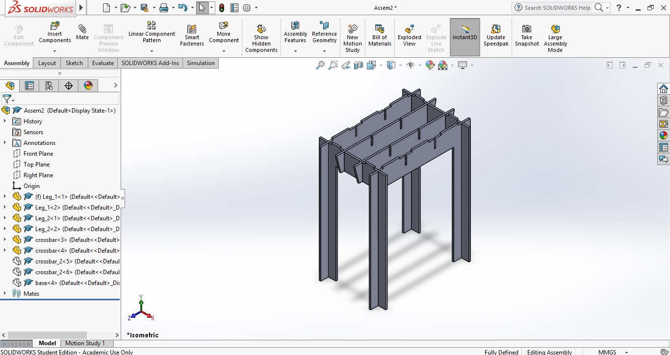
Assembly in Solidworks
With all the parts designed for me was a good idea to create an assembly in Solidworks.
In this case help me to see the final shape of the table and to check the dimensions and found errors (which I did) and correct them.
Another function of the assembly could be to elaborate a small manual to help the building of the table. Figures 6 to 9 show the process.
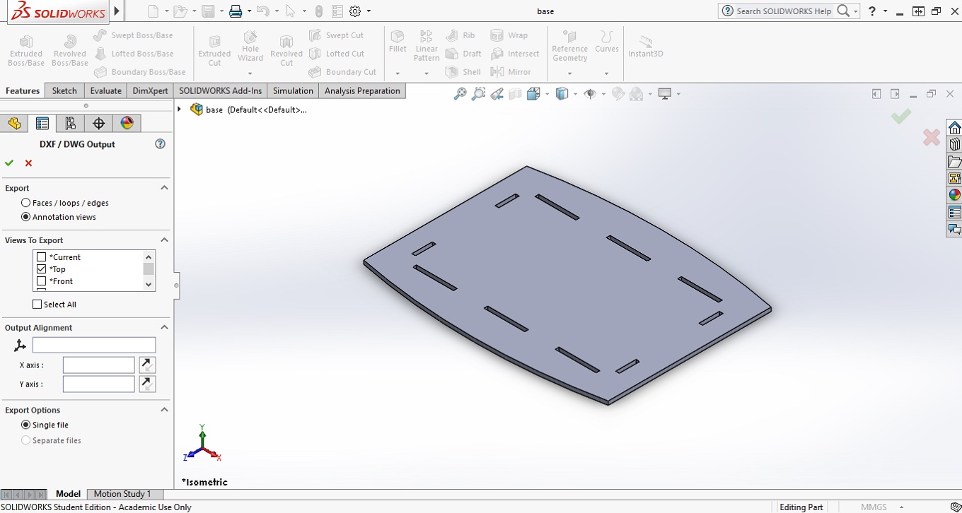
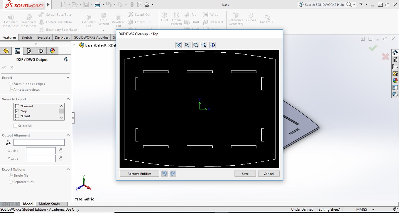
Exporting files as DXF
To make the table is necessary to configure the paths for the tool. This was made using the Enroute software which has a 2D and a 3D mode. To use the 2D mode of Enroute is necessary to have the pieces in a DXF file. To obtain the DXF files in solidworks is necessary go to File – Save as; and choose DXF. This will open a dialog box when the view that is wanted must be check and the DXF file is obtained. (Figures 10 and 11).
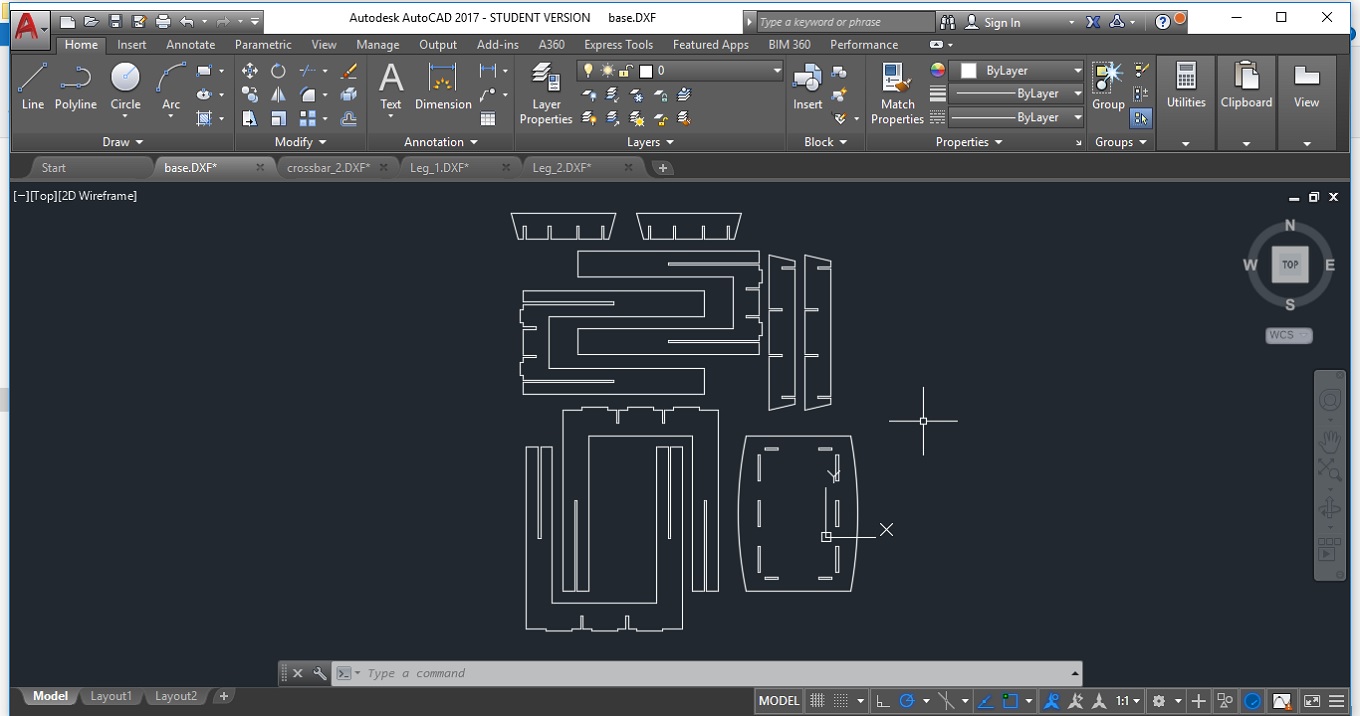
Once all the parts of the table were
exported as DXF is a good idea to put them together in one file. For this purpose AutoCAD is
very useful (Figure 12).
Making the table
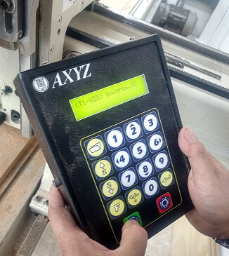
To make the table, an AXYZ 4008 CNC router. This Router has a process area of 244 0 x 1220 mm, which allows to work big pieces. The tool used in this case was a three flute upcut spiral. Once the toolpath is configured in the Enroute (with compensations for the tool diameter) a gcode file is generated and this file must be send to the machine. This CNC has a small key (Figure 13) which is enough to give it commands. Some of the commons commands are:
- F10 - Fix the tool origin
- F24 - Configure the upper surface of the sacrificial sheet
- F20 - Configure the material thickness
- F13 - Move to pre-set origin with F10
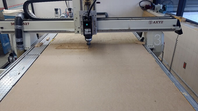
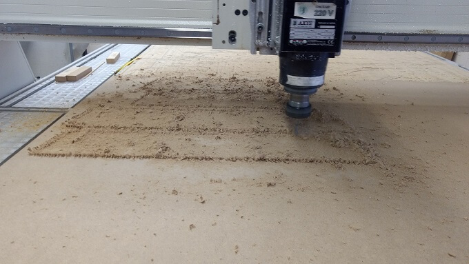
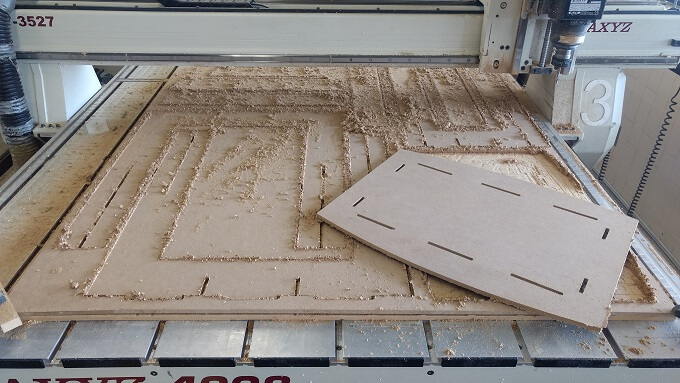
With the file loaded in the machine and the origin and material thickness set the CNC will start cutting the parts. In Figure 14 to 16 the process can be see.
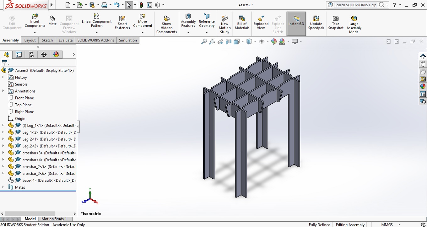
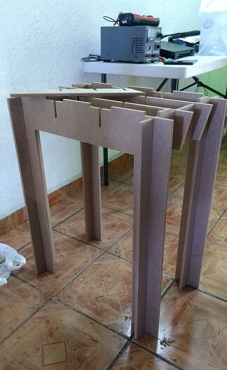
Assembling the Table
With all the parts cut the only thing left is to put together the table. The process is exactly like the assembly in Solidworks (Figure 6 to 9).
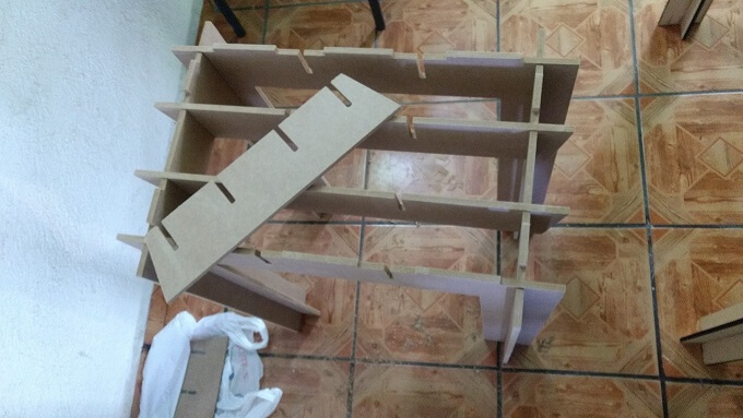
The first step Is to join the legs to from the rectangle, then fit he long crossbars (Figure 17 and 18).
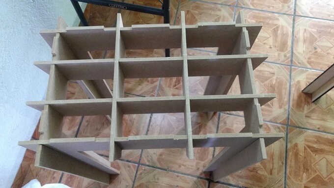
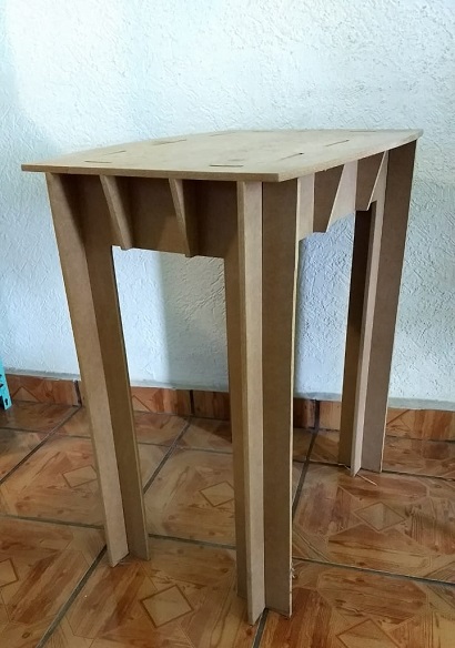
With all the crossbar in place the top must be place in position (Figure 19). With the help of the slots was very easy to find place it. The finished table is shown in Figure 20.
Files
In this section the files generated during the development of the assignment will be available
to download.

|
|
|
|
|
|

|
| base.sldprt | crossbar.sldprt | crossbar_2.sldprt | Leg_1.sldprt | Leg_2.sldprt | Assem2.sldasm | Table.dxf |