Task: Laser Cutting
Demonstrate and describe parametric 2D modeling processes
Identify and explain processes involved in using the laser cutter.
Develop, evaluate and construct the final prototype
I have never used a laser cutter or vinyl cutter before in my life, so this was a totally new experience for me. I accomplished most of this work during the 2017 cycle. During this cycle, I mostly worked on getting familiar with the different cutting machines at Lorain County Community College (LCCC) Fablab. I even got to see the machines taken apart and moved to a new facility. Since the 2017 cycle, I acquired my own Laser Cutter-engraver, and I discuss that later in this assignment. It was interesting to see one of my instructors, Chris Rohal, add print servers to the laser cutters, and a dedicated PC to the vinyl cutter, and then trouble-shoot everything until it worked. I also experienced one of the lasers needing a new tube,which my other instructor, Scott Zitek, replaced. I even observed lab supervisors Ryan and Chris perform routine maintenance on the lasers and 3d printers, such as cleaning mirrors. Also, while I was at LCCC, I saw the construction of a couple of mobile FabLabs. LCCC is a very busy place, with many VERY capable individuals.
The first machine I used was a Roland Camm-1 GX-24 Vinyl Cutter (http://www.rolanddga.com/products/cutters/gx24/default.asp), which is basically a plotter with a razor blade as the stylus. It is mostly used for cutting vinyl, but it can cut other materials as well, such as cloth, vellum, and very thin soft metal like copper. A machine like this costs roughly around $2000. I produced some simple files using CutStudio and transfered them to a PC dedicated to this machine, which was running a proprietary package by Roland.
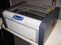
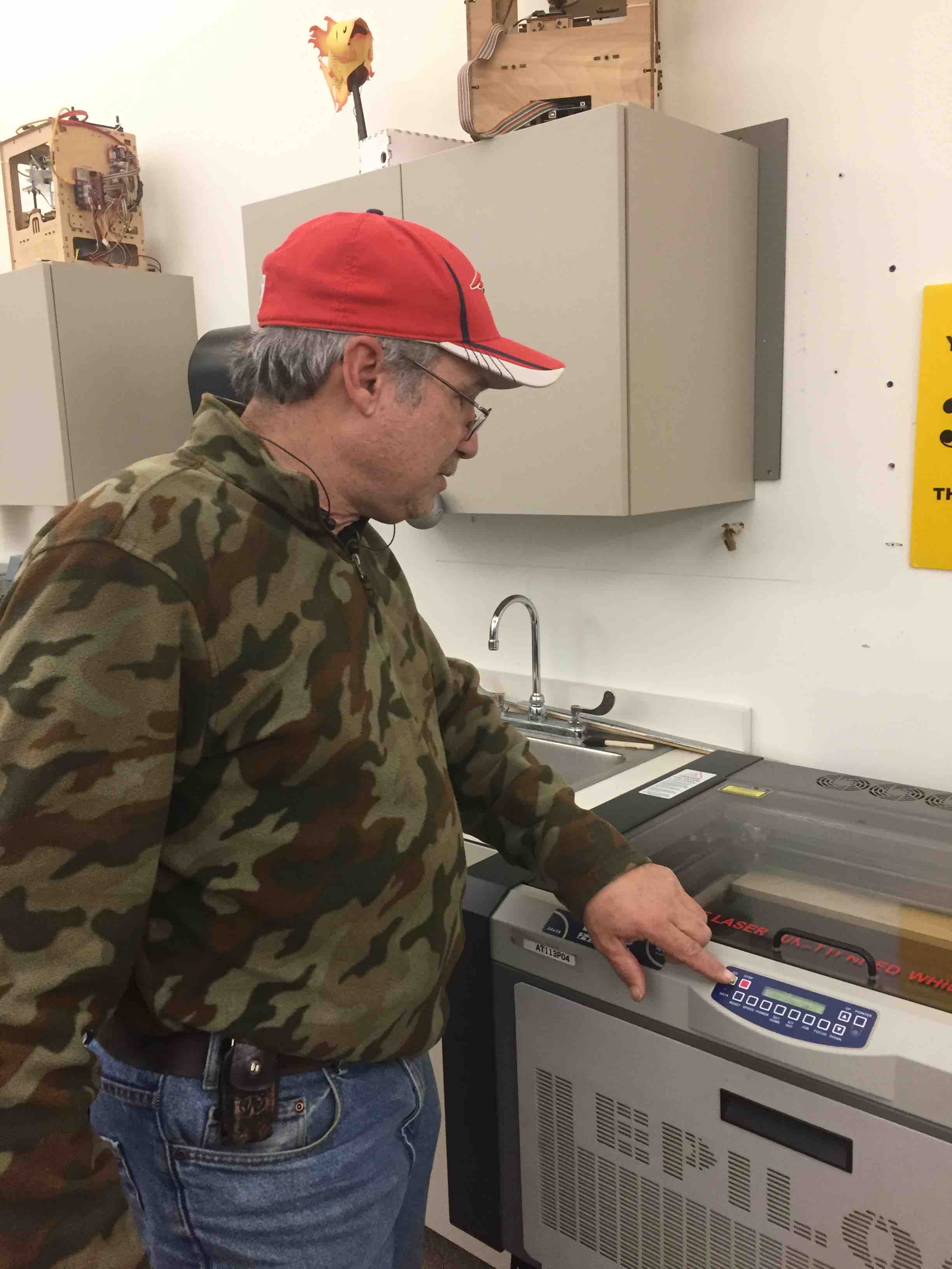
The next machine I used was a laser cutter made by Epilog Laser (http://www.epiloglaser.com/). This is a low power CO2 laser capable of cutting up to 1/4" thick acrylic sheet. It can cut and/or engrave plastic, cardboard, acrylic, marble, mat board, and leather. This machine does cut with a high temperature beam and does generate smoke. There is a filtration system on the machine. It is important to know if the material you are cutting is going to release toxic smoke. There is a guide sheet with settings for recommended materials you can use. If the material is not on the list, you should ask the Fablab attendant.
Vinyl cutting with CorelDraw and CutStudio:
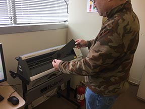
This part is a little redundant because it overlaps what I did in the previous week in Computer-Aided Design. I have experience with CorelDraw from years ago. I have never used a vinyl cutter before. My instructor described it as a plotter with a knife instead of a pen. I was familiar with plotters from years ago. The machine at Lorain County Community College was attached to a dedicated Windows-based desktop computer. The desktop communicated to the plotter through a USB port. My instructor, Scott Zitek, explained that CorelDraw was the software which was used with the vinyl cutter.
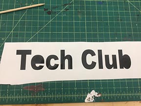
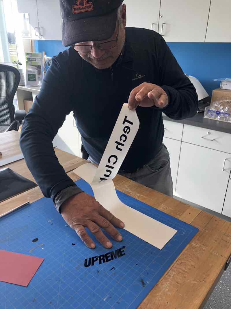
The piece of Vinyl I was given by my instructor was approximately 2 inches by 12 inches. I thought I would attempt a simple sign that I can cut on the vinyl cutter which reads "Tech Club". Since this was the first time have ever used a vinyl cutter, my instructor provided me with some one-on-one instruction. First, he guided me on how to load the vinyl into the machine.
First, I place the piece of vinyl stock in the vinyl cutter. It measures the size of the vinyl. It measures the size of the vinyl in millimeters. Write the measurements down.
Next I start up CorelDrawX5 and pick a font to cut:
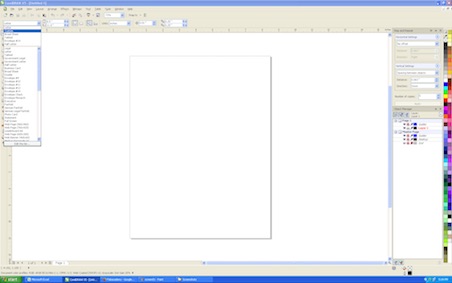
At that point, Corel kept giving me problems. I decided to try CutStudio.
I started by typing the letter A.. I then dragged my cursor over the letter, and then right clicked to get a pop-up menu, wherein I selected "Properties".
I clicked on the "Fonts" pull-down menu and viewed what fonts were available.

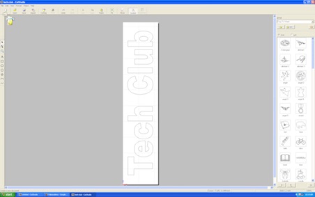
I entered the text "Tech Club". The Properties pop-up window is persistent, so I selected my text and then clicked "Size and Shape" tab and then entered 90 degree angle for "Rotation Angle" dialog box..
The result of my inputs displayed immediately.

I decided to change the font once again to something simpler.
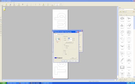
Next I press the "Print" icon and select "Roland GX-24" from the pull-down box. Next, I press properties, and enter values for cutting area which match what the Roland generated for the vinyl stock. In my case, the dimensions were 56.6mm width and 261.3. Note: If your desktop is directly connected to the cutter, you can press the "Get from Machine" button. If your cutter is networked, this button does not work.
Press the "OK" button and the laser starts knifing the vinyl. Printing is straight forward using Roland print driver. After the printer cuts the vinyl, it is time to weed. I liked using my Leatherman tool more so than the Exacto knife at the LCCC Lab.
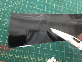
Peel background out.
There you have it.
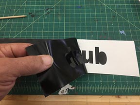
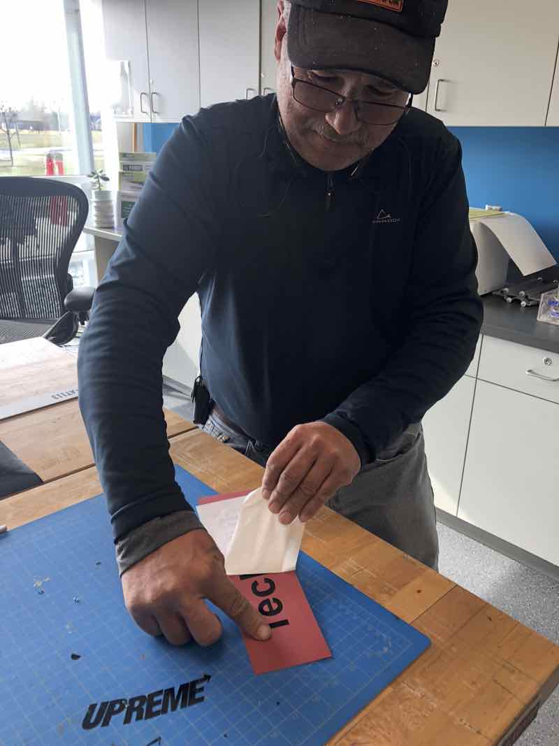
After weeding, we apply transfer tape.
The sign is ready to apply. All that is necessary is to remove the adhesive liner on the back of the decal, press and apply. Once the decal is adhered to the intended surface, just remove the masking tape from the front of the decal.
Update: LCCC moved their lab to a new and improved facility. As a result, they reconfigured how the Vinyl cutter/plotters work. Instead of a dedicated PC connected to the plotter, a print-server device connects a group of desktops to the Roland plotter. I decided to perform the lesson again. Everything went smooth. I just needed to make sure I used the left plotter for the front row of computers,and the right plotter for the back row. The results were similar to the 2017 cycle,and more convenient.
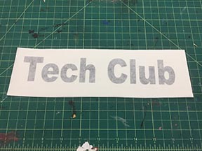
Detach vinyl decal from backer.
Apply decal to application surface.

Hero shot.
(File for CorelDraw: tech club.cdr)
(File for CutStudio: tech club.cst)
Corrugated Plastic with Solidworks on Epilog Laser:
Solidworks is a large application which I have no prior experience with. I tried loading it on my 3 year old Lenovo laptop. The application brought the laptop to it's knees. The LCCC Fablab has two very capable workstations with Solidworks already installed. I ventured onto one of the workstations and started to explore.
Found a menu which had parametric capability, or more correctly, equations.
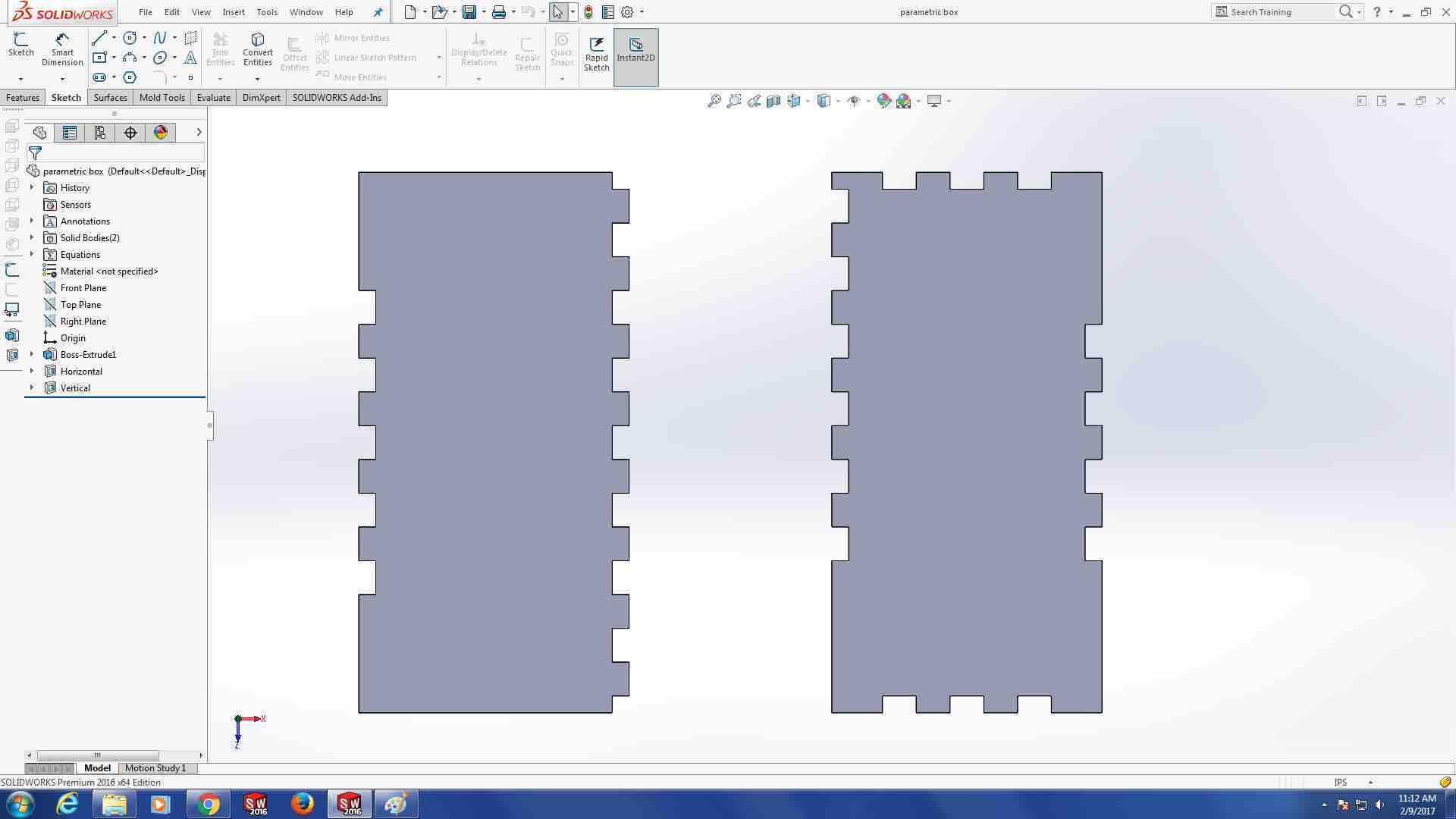
Drill into equations on side panel. See formulas for slot width.

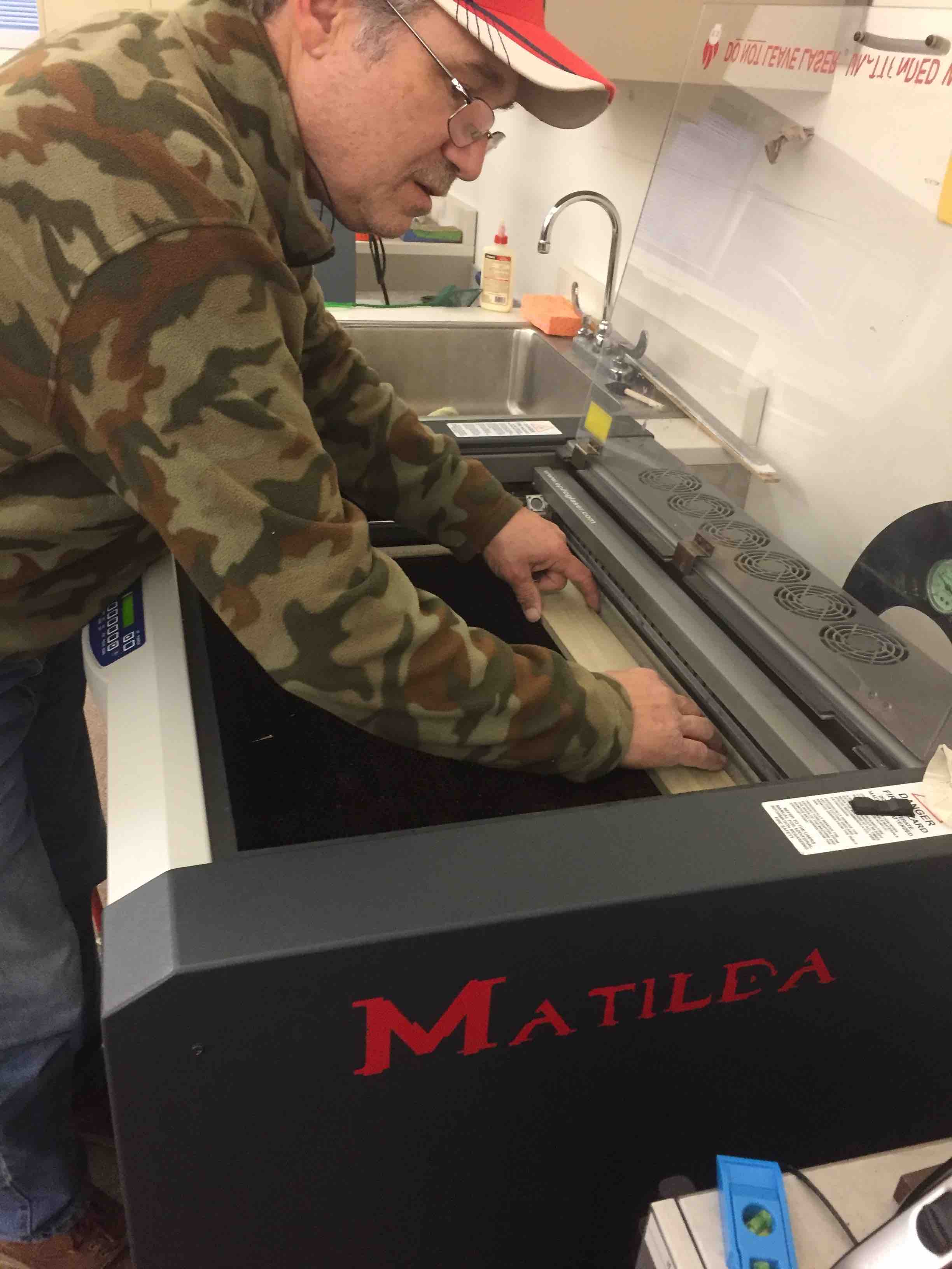
The equipment I used was called "Matilda," an Epilog Helix with a 40 Watt CO2 laser, the larger of two CNC laser cutter/engraving machines available at LCCC.
I wanted to use corrugated plastic (coroplast). I went on line with the lab supervisor and checked a document developed at the lab tabulating recommended laser power and feed rates for different example materials. Coroplast was not listed in the Fablab guide. I also checked with the lab manager to see if the material was safe to cut, since it was not clear on the guide sheet if corrugated plastic can be cut. He didn't know for sure, so I researched more. I found a nice guide onthe web from Twin City Maker's website here: https://www.tcmaker.org/wiki/images/c/ce/Basic_Laser_Packet.pdf This guide lists good rules for laser cutter operation,as well as a comprehensiove list of materials you can AND cannot cut/engrave. I found it very helpful. This website also has a list of power and speed setting recommendations which INCLUDES coroplast: https://www.tcmaker.org/wiki/index.php?title=Laser_Cutter_Settings. I shared this information with the lab manager and I was good to go. I decided to use the settings for coroplast of 40 watts (80%) and 55% speed, and 1200 freq. for cutting the coroplast which I found in this guide.
The lab manager also explained that the laser beam head needs to be adjusted up and down to focus beam energy on the part. The machine was already focused for sheet material, so we proceeded to cutting the part. Up to this point, I had never operated a CO2 laser before, so everything was new to me. I learned that many of the functions of the Epilog Laser are controlled through a printer driver purposefully programmed to trigger different features of the laser. This seems rather pathological to me, and I found it to be awkward and confusing. The laser cutter will run in "cut mode" if the image sent to it as a thin line, or "hairline". Otherwise it will "raster" the image which creates an etching or engraving effect. For this example, "hairline" is the correct method in this instance.
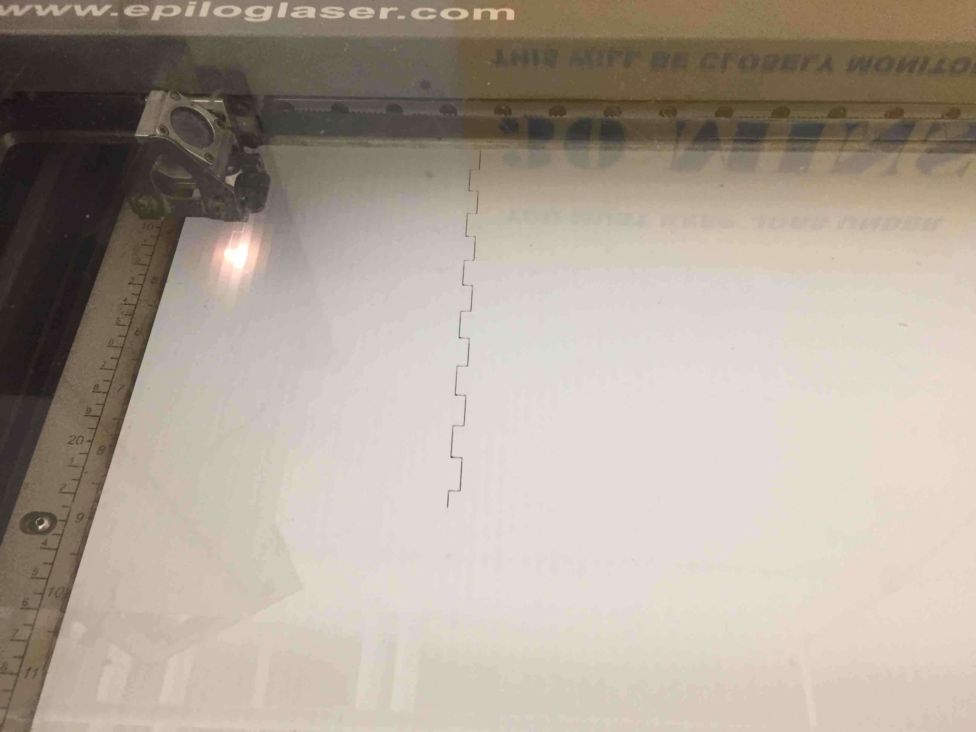
The corrugated plastic cut very well. I ran the cut twice to make sure the beam cut through all the way.
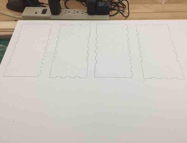
The cutouts separated from the parent material with little effort.
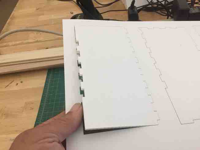
The design needs continued work. I did manage to gauge the thickness of the material to the pattern pretty well. However, the overall design really did not produce anything very useful.
Engraving (Rastering) with CorelDraw:
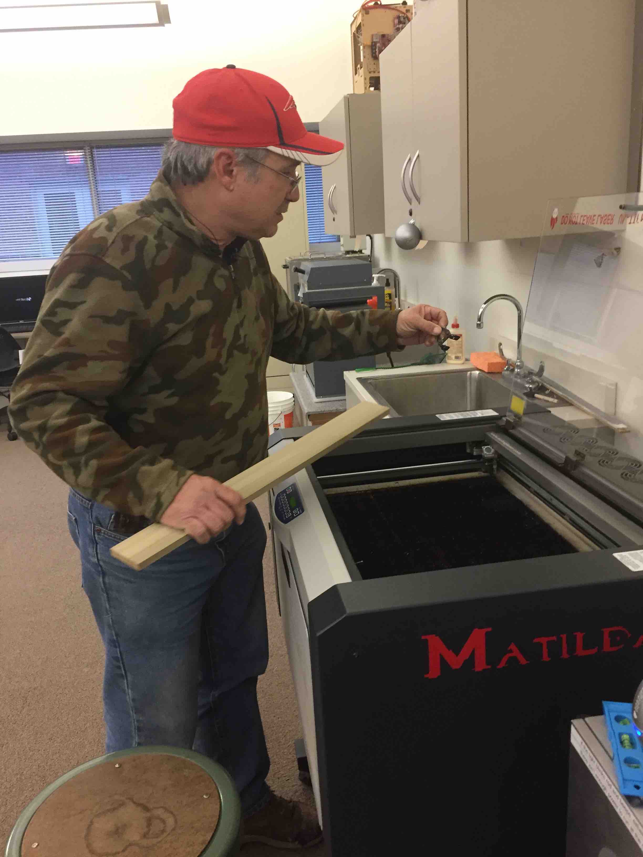
Next I try engraving a piece of Poplar. I used a 1" x 4" board that was 4 foot long. I had my daughter cut it in half with a hand saw so it would fit on the bed of "Matilda." There is a setup procedure required for this machine where you set the height of the laser head with a metal go/no go gauge. I used a piece of paper between the part and the gauge. I moved the head down incrementally until it contacted the paper which I slipped back and forth on top of my workpiece.
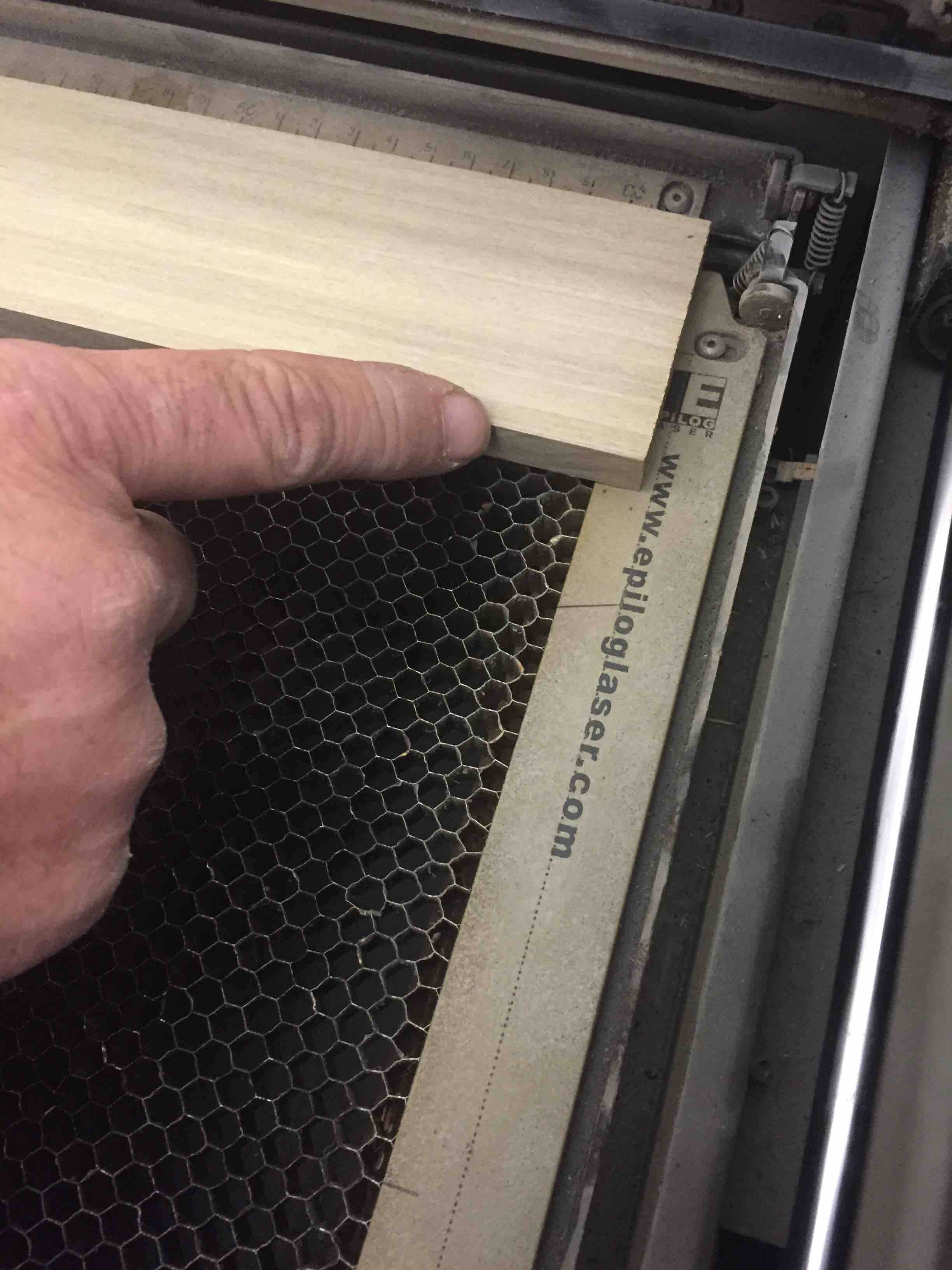
Next I try to fit the piece of wood into the bed of the machine.
At 2 feet, the piece fits in. The honeycomb under the part helps draw fumes down and out of the laser cutter. The wood extends slightly beyond the honeycomb bed, but well before the end stop. I notice a dotted line on the end plate. I think this may be a physical limit of the machine.
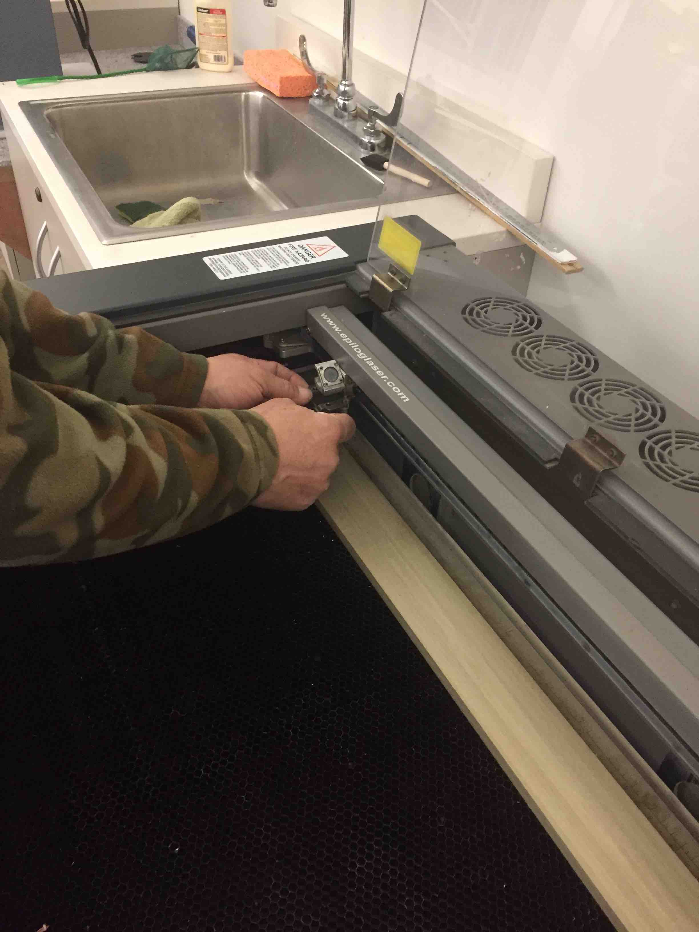
Stow away the gauge block before cutting.
The display shows which file is next to print. I prepared my file using an older version of CorelDraw, Version X5. There are specialprint drivers for the Epilog machine which only works with Version X5.
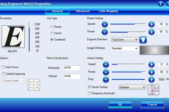
In this driver, you have settings to filter for engraveonly, engrave and cut, or cut only. In addition, there are settings for power and speeed for cut mode and engrave mode. Going back to the Twin City guide sheet, I decided to use power of 50 watts (100%) and speed of 60% Raster mode only, 300dpi. Once I printed the job to the laser, I had to go to a white-board in the Fablab where you write your name. Old school cue. Make sure your file is the one displayed on the machine before pressing the green "Start" button.
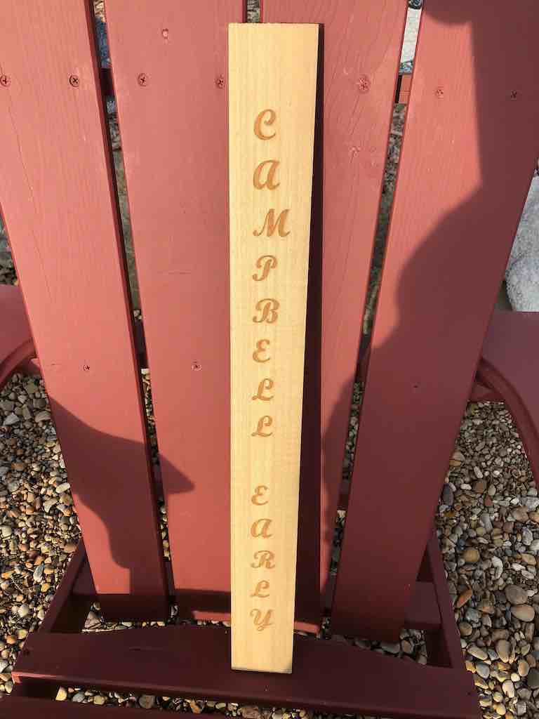
It starts to raster cut the wood with the words "Campbell Early". That will make a nice sign for a row of grapes in my vineyard.
Experimenting with Antimony, Chief Architect, and Press Fits with a Chinese Laser
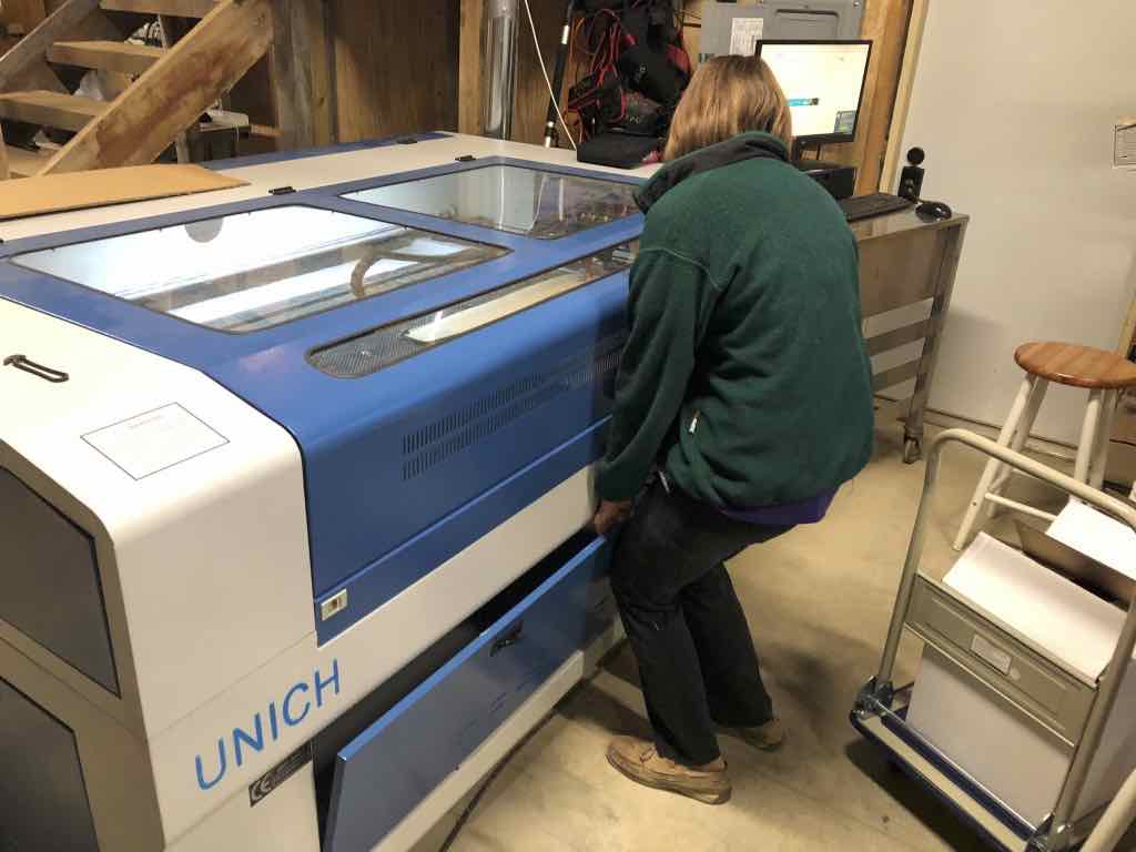
Having gained a little experience with laser engraving, I went ahead and purchased and imported a laser cutter from Jinan Unich Machinery Co.,Ltd. http://www.unichcnc.com/html/About_us/. I arranged transportation, customs, and FDA approval. Importation was not a simple task and took about two (2) months.
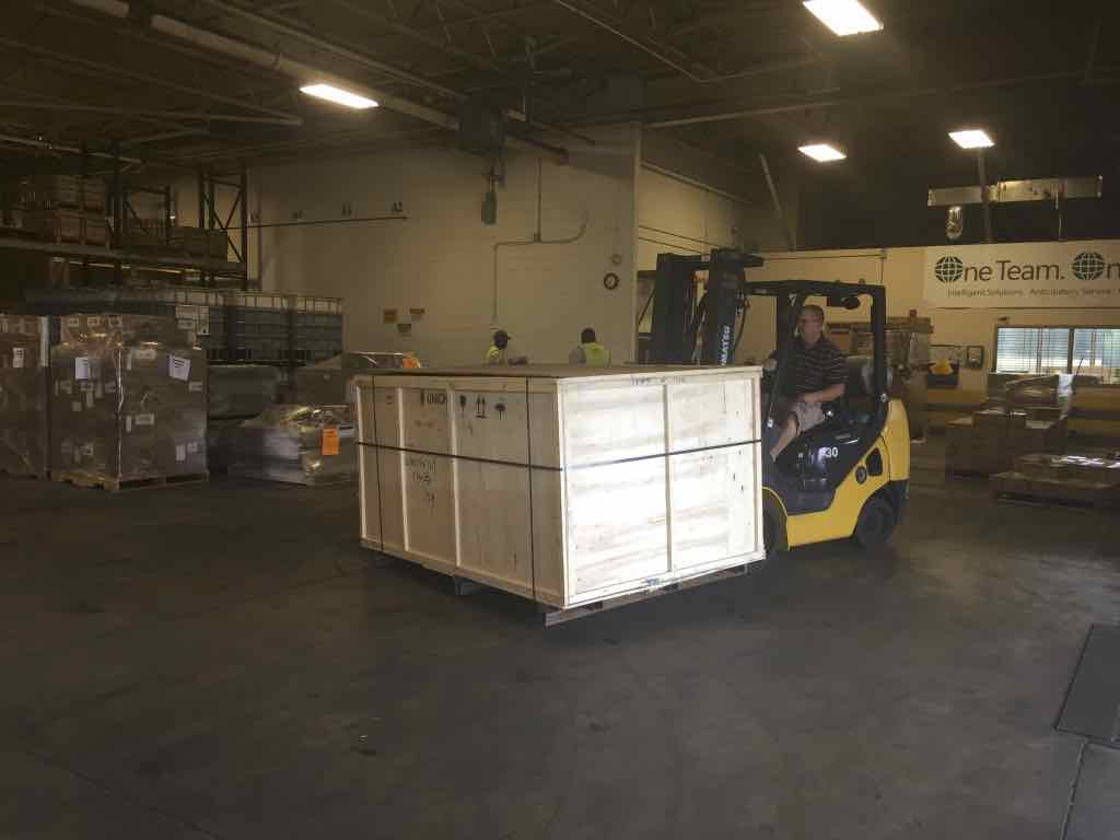
The machine was transported by ship to Newark, NJ, and then by truck to Cleveland. I took my truck and drove 25 miles to pick it up. Machine weight 800kg. (1760 lbs).
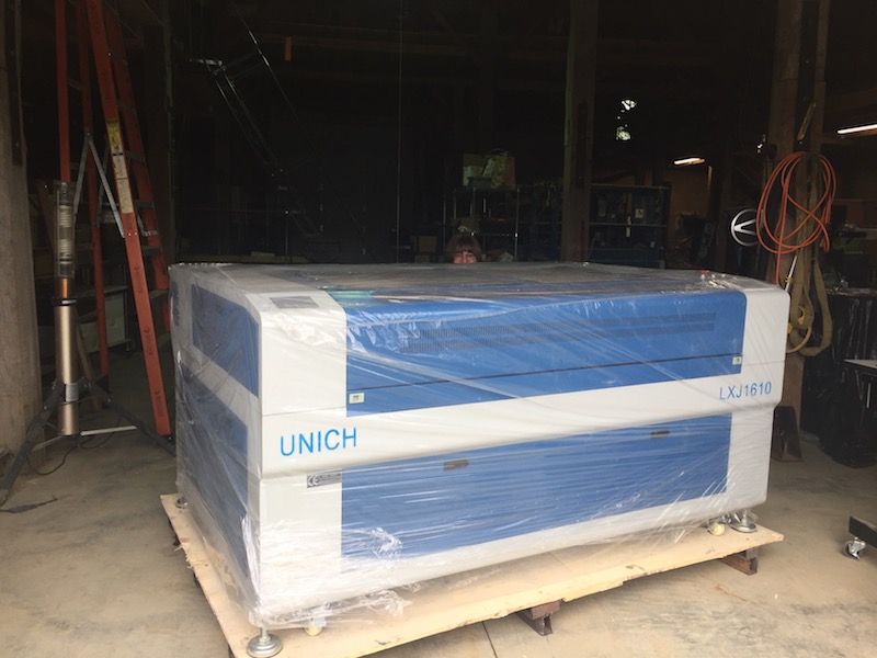
This is a Unich LXJ1610. I unloaded the machine with my Caterpillar 6000 pound capacity telehandler and placed it inside my workshop. Once I uncrated the machine, I was able to roll it about the workshop with built-in casters. Blower, laser tube, chiller, compressor, single-bottle rotary and 5-bottle rotary attachment were all packed inside neatly inside the machine. I purchased it for the workshop at my winery, and to avoid the long drive to LCCC and the long wait for Matilda. It seems that laser cutters are the most popular resource at the various FabLabs I have visited.
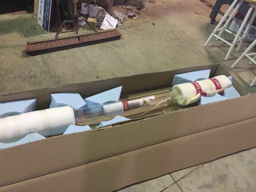
It is equipped with a 175 watt (W8) laser tube with a 1600mm x 1000mm bed. The laser tube, manufactured by Reci, was shipped in it's own box.
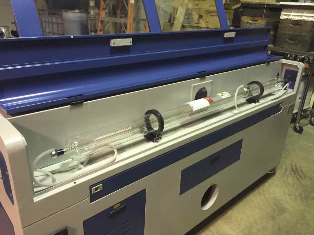
We carefully installed it into the back of the machine, filled it with distilled water, connected it to the chiller, and followed the manufacturers instructions for aligning mirrors. We took our time, and this took about 8 hours.
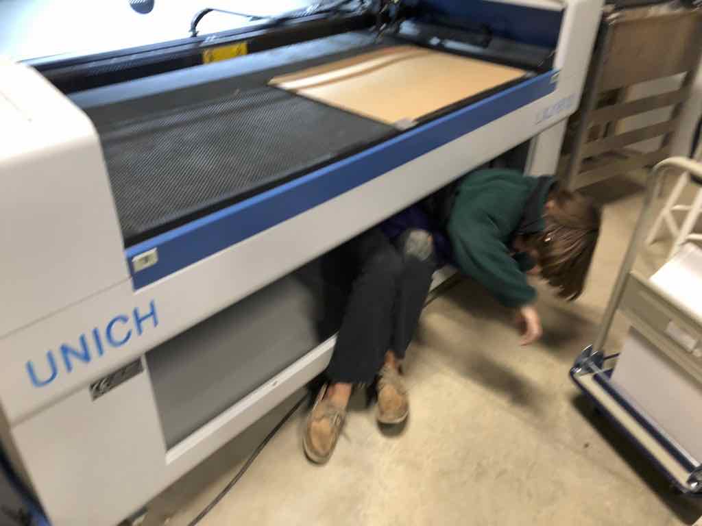
Having all the extra components shipped inside of the machine caused the machine bed to go out of level. This was a good time to train my teenage daughter on the importance of the level of the honeycomb table to the crossarm, and have her crawl inside to get it done. The table operates on four (4) lead screws interconnected by a very large serpentine belt to a single stepper-motor. Each screw needed to be adjusted to get each corner equal to each other. We first leveled the machine,then used a level to rough in the table. Last step was to move the laser head to the four corners and see how much space from the table to the head with a 20mm gauge block.
Cutting capacity of this machine is 30mm acrylic, 20mm plywood, 20mm MDF.
Now I needed to do some test cuts.
I decided to use Antimony, because it is simple AND powerful at the same time. The graphical interface is intuitive. I wish there was more documentation and example programs. I studied the work that my guide, Chris Rohal, did for Fabacademy 2016 and decided that I would try to improve on the concept he had during that iteration of Fabacademy.
First, I started with a circle, and then added rectangles. Next I added the function "Difference", linked the circle as the primary operator, and subtracted the rectangle as the secondary operator. That worked, so I inserted the array function in between the rectangle operator and the difference operator. Quick and easy!
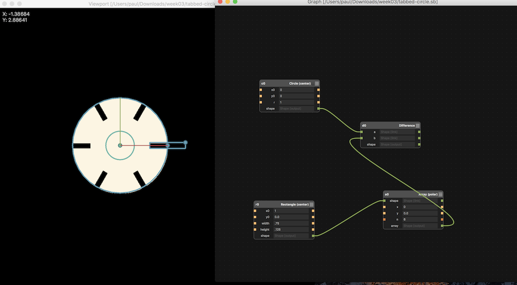
Screen Shot 2017-10-27 at 11.00.05 AM.png
All the slots are equal size. I wish I knew how to change the code within the array node, so I could use the array function to keep increasing the size of the slot. I believe it is possible. I just don't know how to do it and I have no documentation or anyone to help me with Antimony. I suppose I need to spend more time in Somerville, Massachusetts. I saved the above file and I will use it to make some fidget parts to play with later.
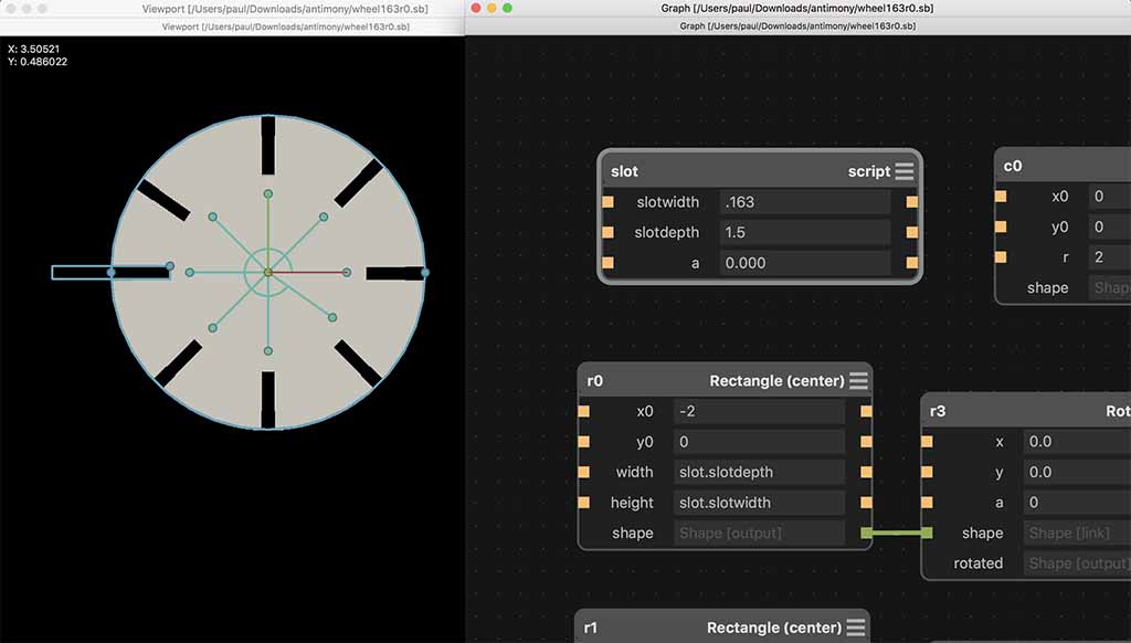
Next, I redesigned and added a "script" which defines variables I called "slotwidth", "slotdepth", and "a" for allowance. The strategy here is to implement long hand 8 slots, each with different polar ordinates. The initial slot is valued at the initial constants "slotwidth" and "slotdepth". The remaining 7 slots increase by "a", "ax2", "ax3", "ax4" and so forth. In this way, you can easily make a gauge wheel for any thickness material, and create any increment of increasing sizes. For illustration purposes, I made an initial allowance of 0.100" so the increase step would be visible in this document. For my final model, I used an increment much smaller.
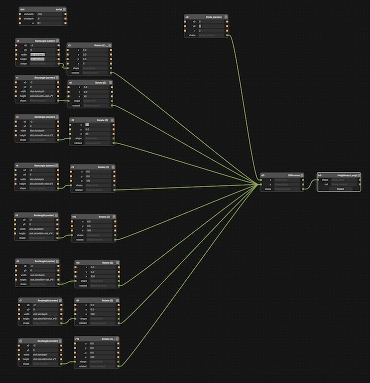
The following illustrates using slotdepth = 0.146", slotheight = 0.500" and allowance (a) = 0.100"
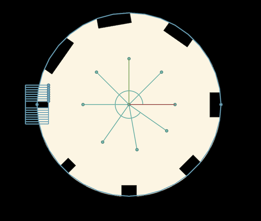
Next, I put in some more realistic values. Slotwidth = 0.170 and allowance (a) = 0.006". The result is not readily apparent on screen, but did make a difference when cut on the laser.

This last step is very important. In order to process the design so Corel could read it as line art and not raster, I first converted the object t to 3D with the "extrude" construct/node. I then connected the extrude node to an export node. Pressing the export button generates an STL mesh file which I later import into Chief Architect with three clicks of my mouse. I don't know what a voxel is, but it has something to do with resolution. The default setting is 23 which produced something that had too many errors. 55 voxels shown here produced files that were too large. I found increasing to near 30 seemed acceptable.
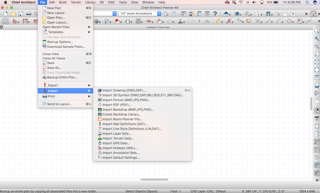
Import the STL file generated by Antimony with Chief Architect by pressing "File" - "Import" - "Import 3D Symbol". The next screen generated is your generic Finder screen. If you are using the Windows version of Chief, the screens follow the Microsoft File Manager paradigm
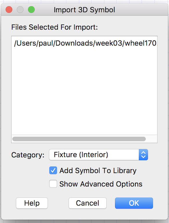
Press the OK button and the Antimony 3D model becomes part of the user library in Chief Architect.
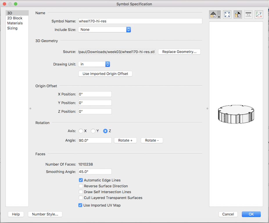
Use the above default settings. They work fine. Press "OK". The model will be part of the User Library of objects at that point.
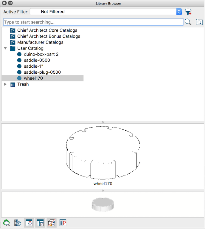
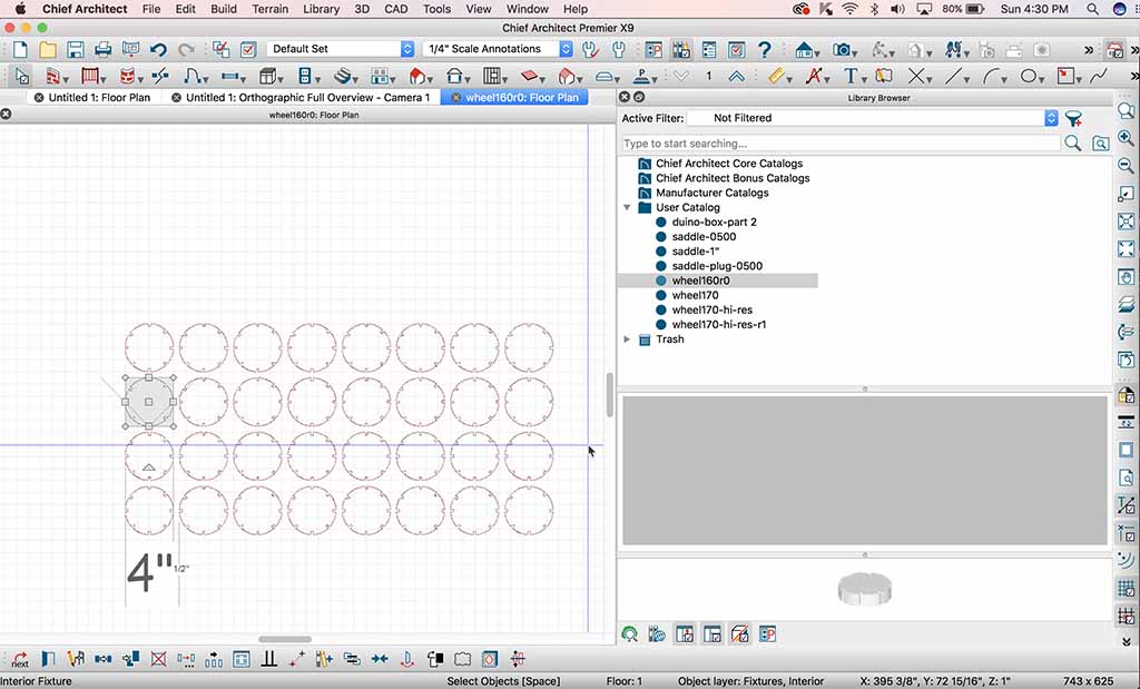
After the model is added, you can use it in 3D or plan mode. I next create a "plan" and add the object to the plan.
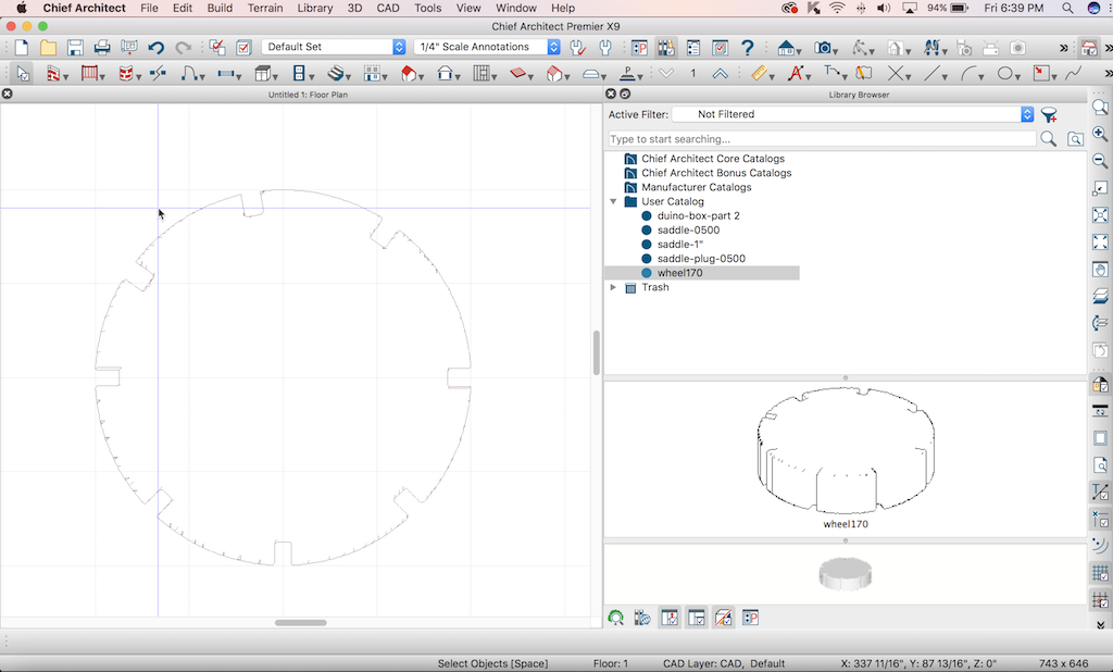
At this point, I decided to call this WHEEL170. I perform "File" - "Export" and will choose DXF as the file type. I had problems with CORELDRAW6 being able to import the latest DXF, so while in Chief Architect, you will need to roll back to Autocad 14 compatibility so Corel can read the resulting file.
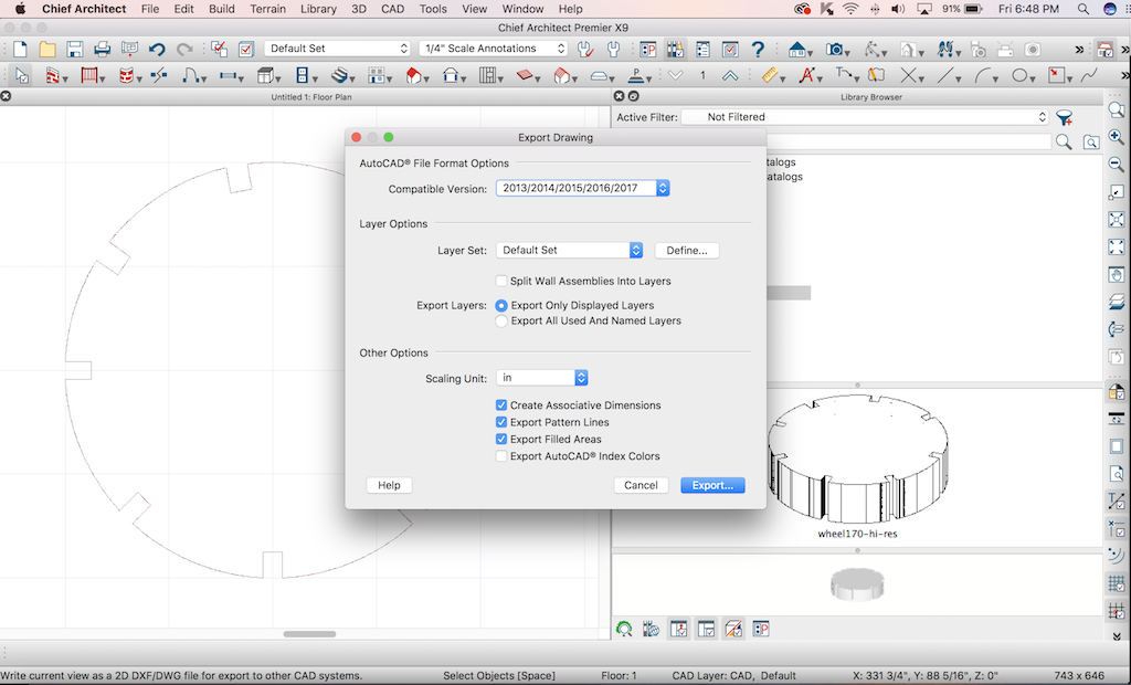
Press "Export..."
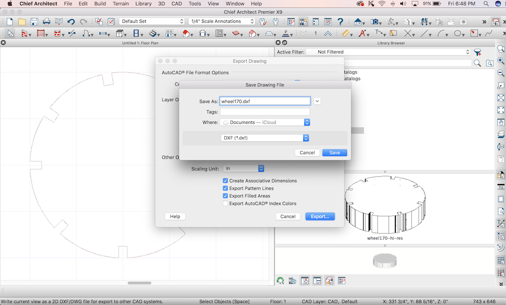
Type in a file name you will use in CorelDraw. Make sure you switch from DWG default to DXF. Move the file onto a thumb drive and get ready to use CorelDraw on the Windows desktop attached to the laser.
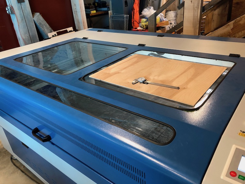
I started with an 18" x 24" piece of plywood. I used a dial vernier earlier to measure the thickness, which is 0.170", the number which I used in my model.
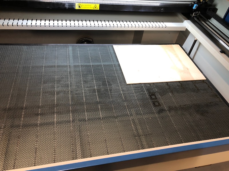
I place the plywood onto the honeycomb bed. Next I will use the keypad on the machine to move the table up until it is 20mm from the part. I like using the manual method of focus rather than auto-focus.
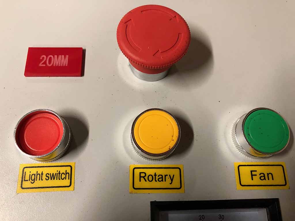
The machine came with a 20MM gauge block.
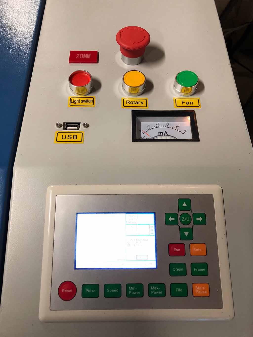
This is the default screen. The cursor keys move X and Y axis.

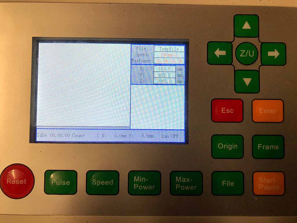
To move the table up and down, you must first press the "Z/U" button. The menu screen changes.
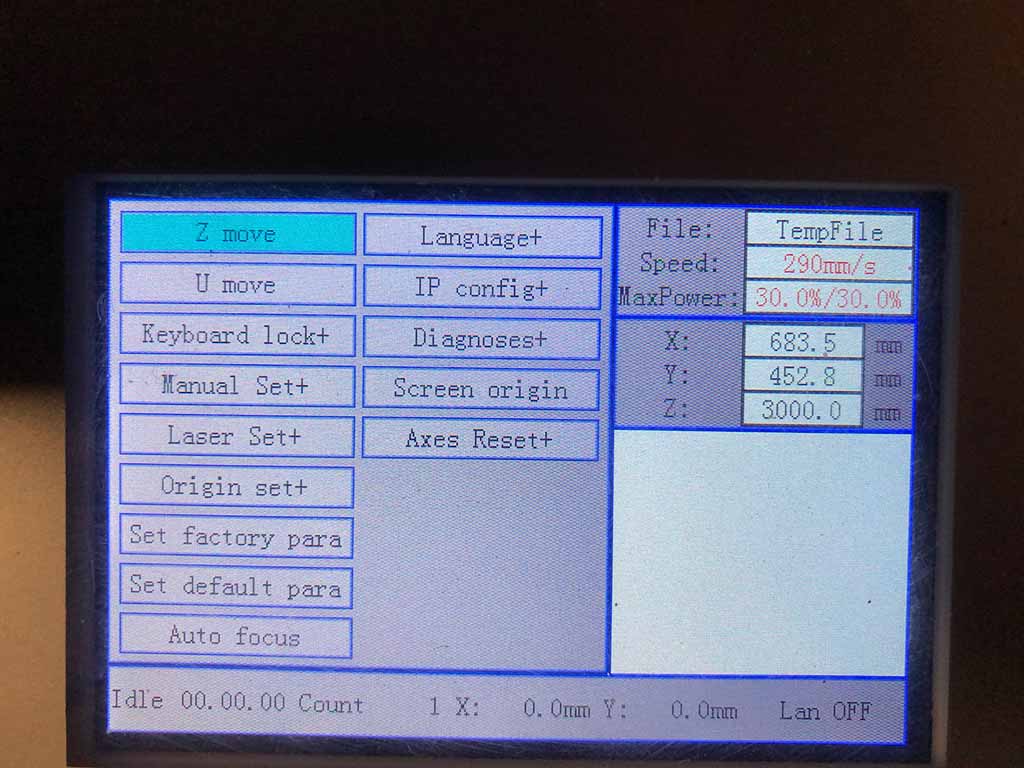
When you are in this screen, the left and right cursor keys move the table up and down.

After you adjust the table height, you must press "ESC" to return to the default menu.
Next, we start up CorelDraw and start a new document, and then import the DXF file generated by Chief Architect. Once the model is loaded, we press the laser cutter icon, which looks like a green dot with white center. This starts up a script for RDWorks.
.png)
Within RDWorks, you can set layers to cut or scan (engrave). Each layer can be set to different power levels and speeds.
You can turn layers on and off. In this instance, we will be turning off the second layer which is for SCAN, which we do not want to do.
.png)
This laser is 175 Watts, so it runs pretty fast travel speed and the power does not need to be set too high. Once your settings are in, press the START button. On this example, I choose to run at 60% power, and 30mm/second. The machine is brand new, so I am still figuring out speeds and feeds.
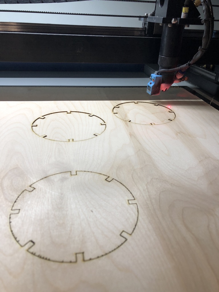
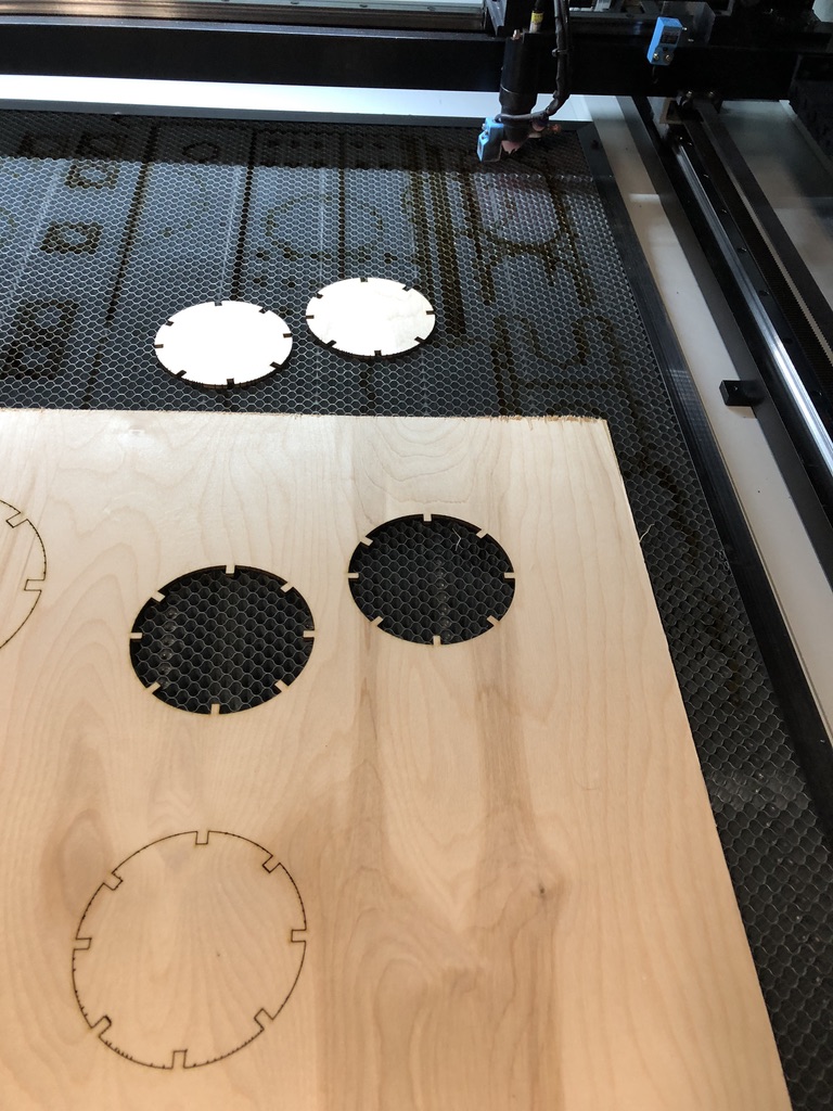
The wheels drop out cleanly from the workpiece. Next, we measure the slots with a vernier. Measurements varied slight from part to part. Actual slot dimensions on one wheel, in thousandths of an inch, are 180, 186, 193, 203, 210, 215, 218, and 223.
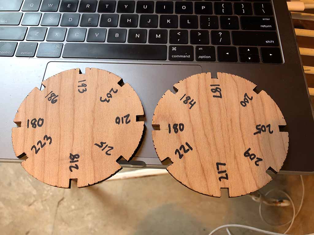
Try fitting the slots between parts. These wheels allow you to fit any combination of sizes together. The best combination in this instance is 180 to 180, just slightly loose. The tool-path was 170 thousandths, so the kerf of the laser is 0.010". Perhaps it can be improved.

The 180 slot fits the other 180 slot nicely. Still a slight amount of play. I think I can reduce cut by 0.010". I next started playing with the script called slot. It basically contains all the parametric variables. I reduced slot width to 0.163" and increased the depth to 1.5". I want all the slots to be all the same width, so I set the allowance (a) to zero (0). Now instead of being a useful gauge wheel, the model is a useless fidget widget.
(File output from Antimony: widget.stl.zip)
(File from Chief Architect: widget.plan.zip)
(File exported to CorelDraw: widget.dxf.zip)
I import the Antimony image into Chief, make repetitive copies, and export as a DXF (Autocad 14 compatible) for CorelDraw6. A couple of notes about Chinese Lasers and RDWorks. RDWorks only seems to work on CorelDraw 6 or CorelDraw5. CorelDraw8 does not allow scripting so you need the older Corel. Also, RDWorks has the ability to import DXF files directly. However, when I tried, it did not scale the model correctly. What should have been a 4 inch diameter disk resulted in a 6" diameter disk.
I use the same process as the gauge wheel to make the fidgets. After they are cut, I removed them from the laser and tried to find something to do with these things. I suppose I can use them in the winery as coasters?

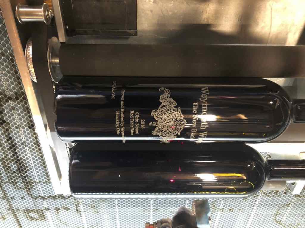
How about a bottle coaster for a laser-engraved bottle of our 2016 vintage of The New Black?
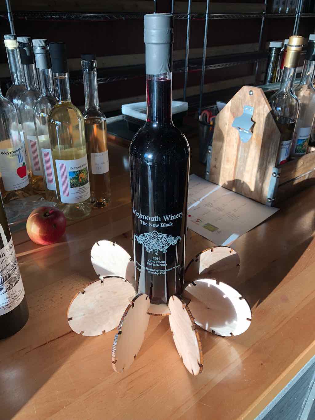
We first engraved a bottle up at LCCC with Matilda and Ryan's help. We tried a couple of designs,and ended up liking this:

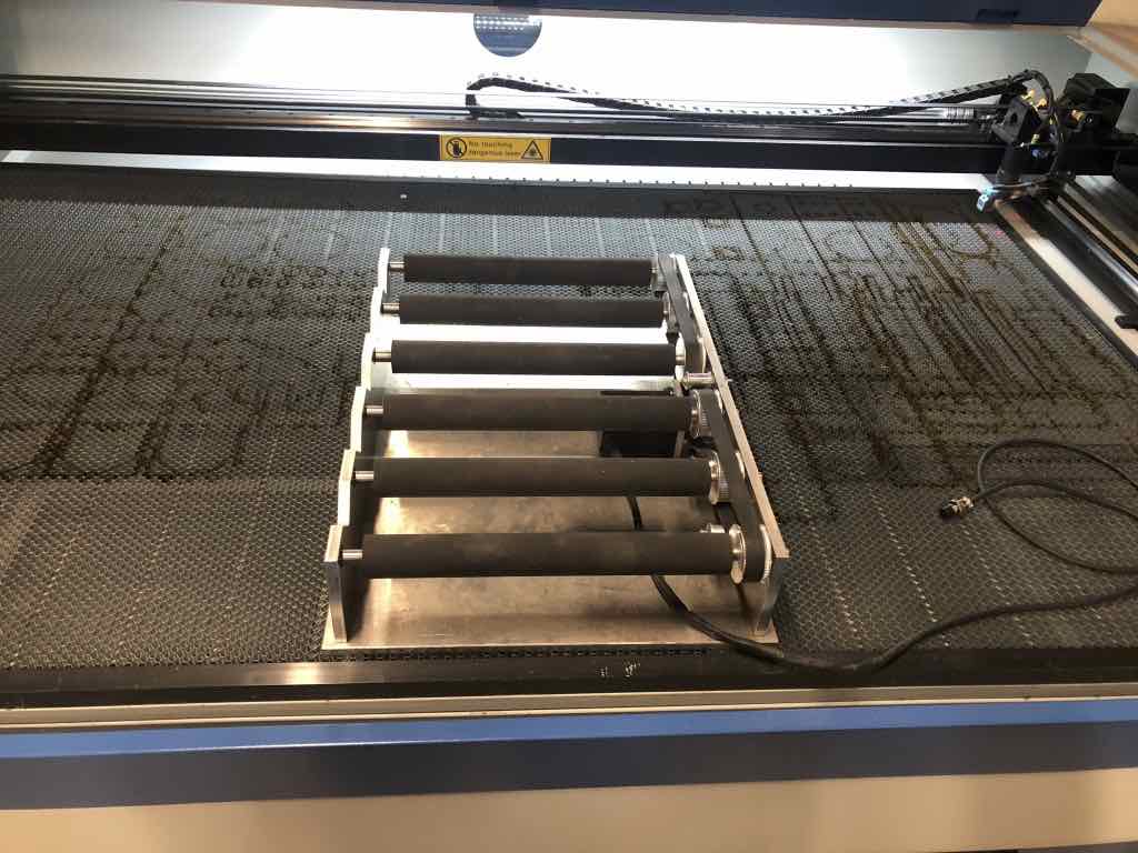
We used the single-bottle rotary axis attachment to engrave the bottle. We did a couple of test bottles and ended up liking the results best when we used 30% power with 150 mm/sec travel speed. After that, we decided to get production rolling. We changed to the 5-bottle roller. Upon further investigation, it turns out the manufacturer neglected to install a 4th axis which is necessary to operate in 5-bottle mode.
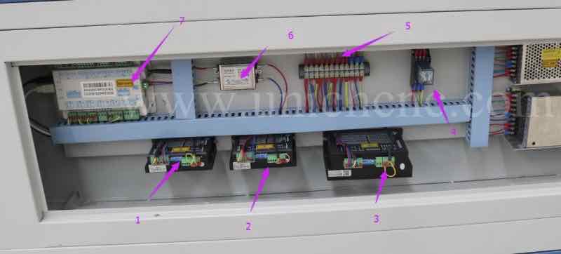
We also discovered the attachment was assembled with the wrong size belt and roller. The manufacturer was kind enough to send us the missing servo drive. We mounted the drive inside the cabinet and added an additional 3-pin aircraft fitting to the machine. The soldering I did in the 2017 cycle came in handy here. After installing the servo drive and changing parameters, we gave the machine a functional test, calibrated how many steps between rollers, and were eventually successful in getting the 5-bottle attachment working.
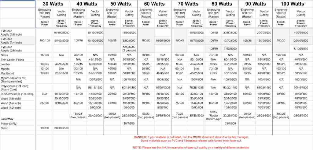
I'm just getting some experience with the machine. Having a large-format laser cutter has some advantages, but also has some drawbacks. You are able to put larger and thicker parts into the machine. However, it is more of a challenge to get parts to lay flat and cut consistently throughout the entire workspace. I have visited Sears Think[BOX], the makerspace at Case Western Reserve University, where they have some large format laser cutters. I found this cutting guide spreadsheet helpful while using my laser. The original sheet is found here: https://docs.google.com/spreadsheets/d/1Dcz3cvCcBPs32yvo-1F11wZ2QqSEchG-daMaAFHtenU/view#gid=0
(The New Black Corel design file: The_New_Black_Noriet-rev11.cdr)