TODO LIST
- Group Assignment : Send a message between two projects.
- Individual Assignment : Design and build a wired &/or wireless network connecting at least two processors.
Introduction
In this week we should need to to network between atleast two microcontroller boards and comminicate etch other. In this week iam going to try some hardware loevel protocols to interconect more than two boards. But they are mainly categerised in to two types for inter-exchanging datas(Serial & Parellel). Also Wired and Wirless communication methods are available. In Wired communication, there are I2C, UART,SPI are the common type of methods that are using to make a network between the boards. I would like to both of them. There are a lot of Atleast i can try them. In wireless communication, commonly used, Bluetooth,WiFi,NFC,RF etc... are the type of methods. I used the Bluetooth module in interface week to communicate the board with my android phone.
Serial communication
Simply, in serial communication we can send a Bit at a time. So it should be the process of sending the Bit at a time continuesly. It is only need two wire when comparing with parellel communications. A bit will transmit or receive for every clock pulse.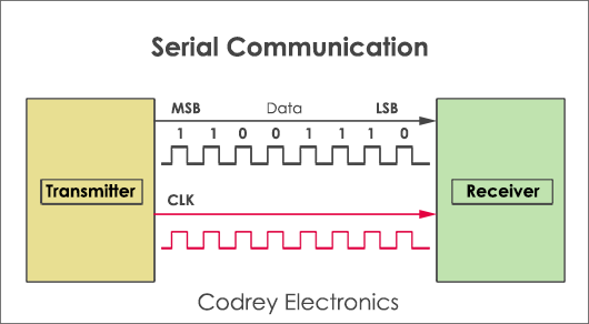
UART(Universal Asynchronous Receiver/Transmitter)
The final piece to this serial puzzle is finding something to both create the serial packets and control those physical hardware lines. Enter the UART. A universal asynchronous receiver/transmitter (UART) is a block of circuitry responsible for implementing serial communication. Essentially, the UART acts as an intermediary between parallel and serial interfaces. On one end of the UART is a bus of eight-or-so data lines (plus some control pins), on the other is the two serial wires - RX and TX.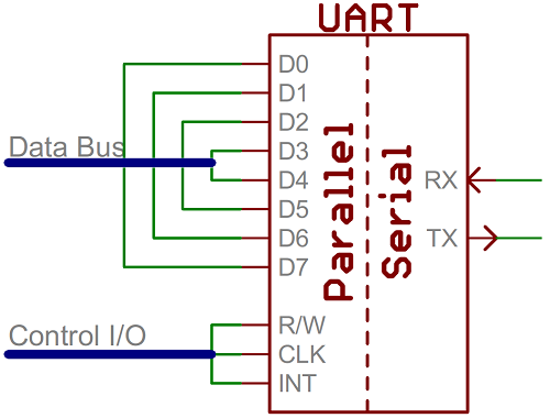
UARTs do exist as stand-alone ICs, but they’re more commonly found inside microcontrollers. You’ll have to check your microcontroller’s datasheet to see if it has any UARTs. Some have none, some have one, some have many. For example, the Arduino Uno - based on the “old faithful” ATmega328 - has just a single UART, while the Arduino Mega - built on an ATmega2560 - has a whopping four UARTs.
As the R and T in the acronym dictate, UARTs are responsible for both sending and receiving serial data. On the transmit side, a UART must create the data packet - appending sync and parity bits - and send that packet out the TX line with precise timing (according to the set baud rate). On the receive end, the UART has to sample the RX line at rates according to the expected baud rate, pick out the sync bits, and spit out the data. Here is the conection between the device.

Software UART
A software universal asynchronous receiver and transmitter (UART) provides the flexibility of asynchronous serial communication between devices with minimal external hardware. ... A software implementation of a UART allows increased system functionality without increasing hardware costs. So ifa microcontroller does not have a Hardware UART feature. The SoftwareSerial library has been developed by arduino to allow serial communication on other digital pins of the Arduino and other AVR microcontrollers using software to replicate the functionality of Serial communication. See the source of information.I2C communication
I used I2C communication before for interfacing some modules witrh arduino development boards. As i mentioned earlier, i choosed I2C communication to do the assignment this week. I would like to know more about I2C communication. So what is i2C communication? The Inter-integrated Circuit (I2C) Protocol is a protocol intended to allow multiple slave digital integrated circuits (chips) to communicate with one or more master chips. Like the Serial Peripheral Interface (SPI), it is only intended for short distance communications within a single device. Like Asynchronous Serial Interfaces (such as RS-232 or UARTs), it only requires two signal wires to exchange information. I2C requires a mere two wires, like asynchronous serial, but those two wires can support up to 1008 slave devices. Also, unlike SPI, I2C can support a multi-master system, allowing more than one master to communicate with all devices on the bus (although the master devices can’t talk to each other over the bus and must take turns using the bus lines).
Data rates fall between asynchronous serial and SPI most I2C devices can communicate at 100kHz or 400kHz. There is some overhead with I2C for every 8 bits of data to be sent, one extra bit of meta data must be transmitted.
The hardware required to implement I2C is more complex than SPI, but less than asynchronous serial. It can be fairly trivially implemented in software.
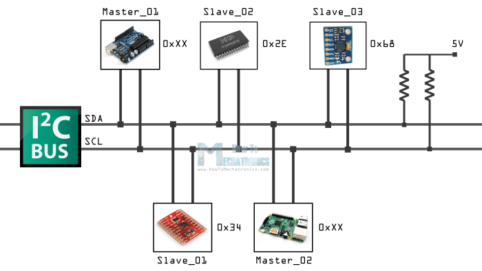
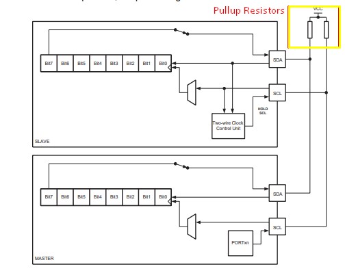
Pull up resistors for I2C Bus lines
Both SCL and SDA lines are open drain drivers. wich means that the chip can drive its output as low, but it cannot be drive it as high. For the line to be able to go high you must provide pullup resistors to the power supply. Usually ued a 10K resitor value for pullup up the SDA and SCL lines.
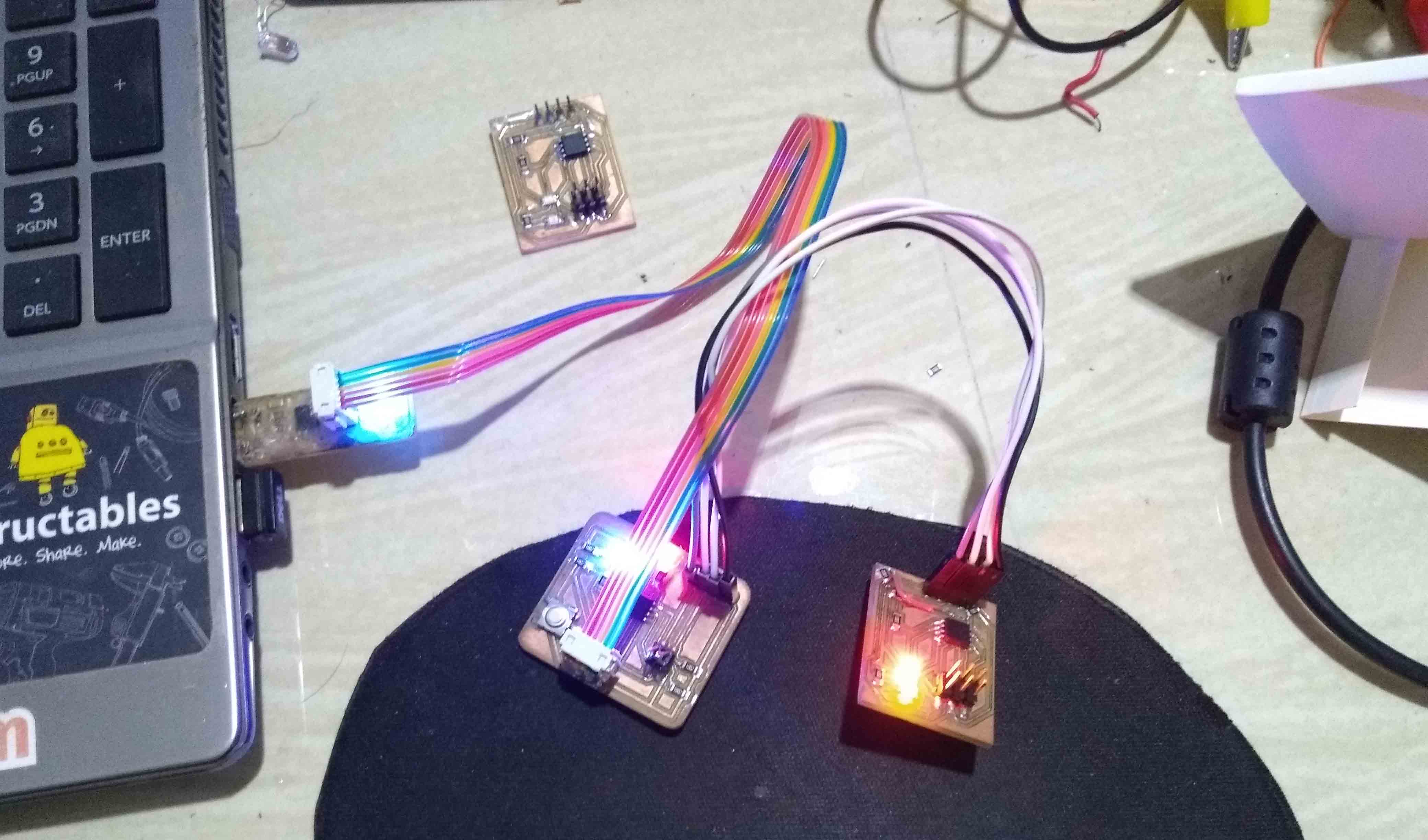
PCB designing and milling
We got much infirmations about I2C. Now lets built some PCBs to communicate each other through I2C bus. I choosed Attiny45 as the microcontroller. First i need to design the Master board then design the slave board. The master board is consist of a Button and LED and slave board have a single LED only. So when i press the button on Master board, the LED on the slave board as well as LED on the master board will glow. SO that is my plan. Now let design the Boards and mill them.
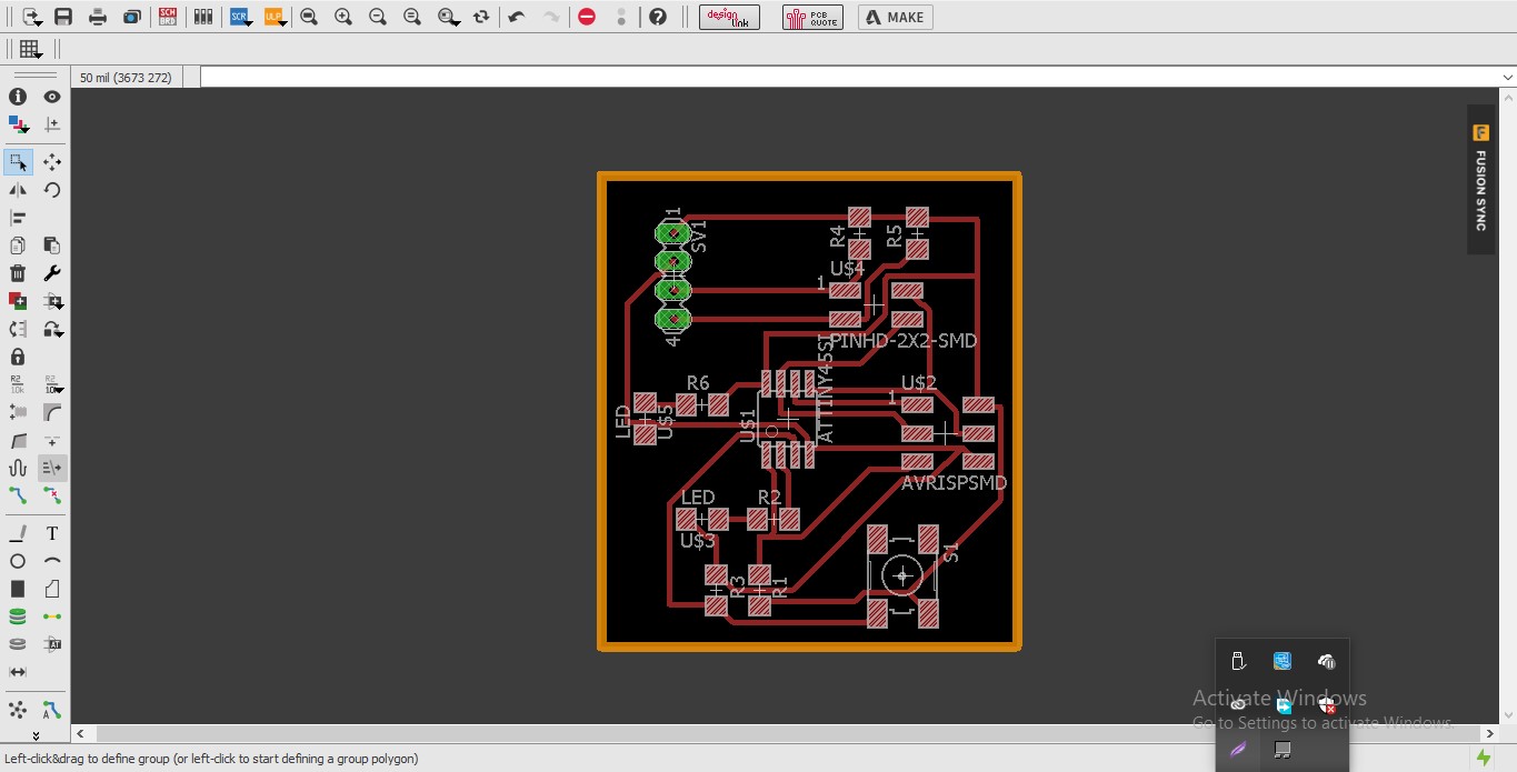
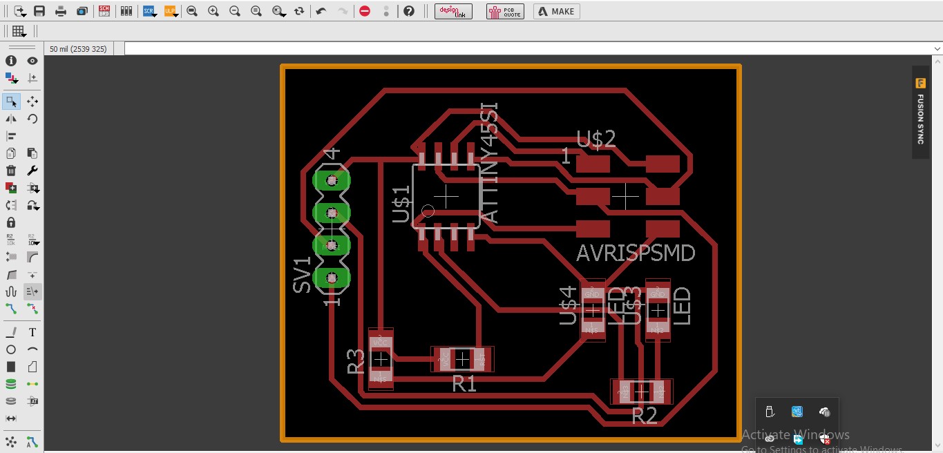
Master Board
First i designed the Schematics and PCB design for the master board. I used two 10K resisters to pull up the SDA and SCL lines.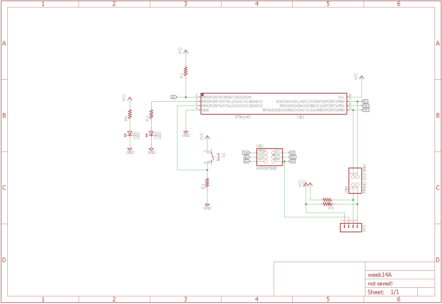
Slave Board
Then after i designed the Schematics and PCB design for the slave board. I used two 10K resisters to pull up the SDA and SCL lines.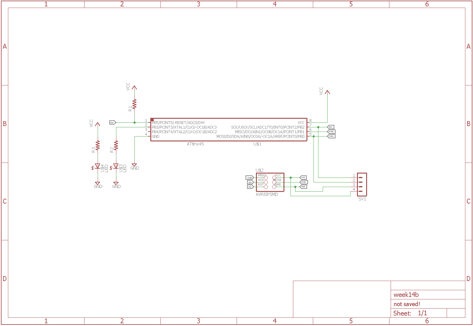
PCB milling and soldering
Now i need to millout the PCB using modella MDX20 PCB milling machine. I used the same steps that i followed on my previous elecronics design weeks.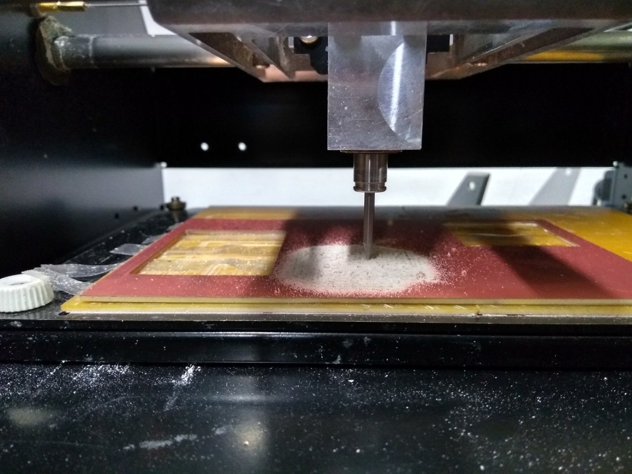
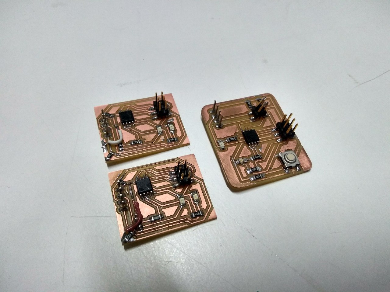
After milling the PCB. i pullout the PCBs from the milling bed. The PCBs are made differently. I milled three times for the three boards. i made one master board and two slave boards. Then i soldered all the components to the boards carefully.
Programming the board
Now i need to program each of the boards. This is little complicated one because i need to do the three of the boards communicate properly. But while iam testing one of the slave board, i accidently removed the FabISP programmer while the code was uploading. Now i cant program the board. But for now i go with the other slave and master boards and i should troubleshoot the board and recover it later.
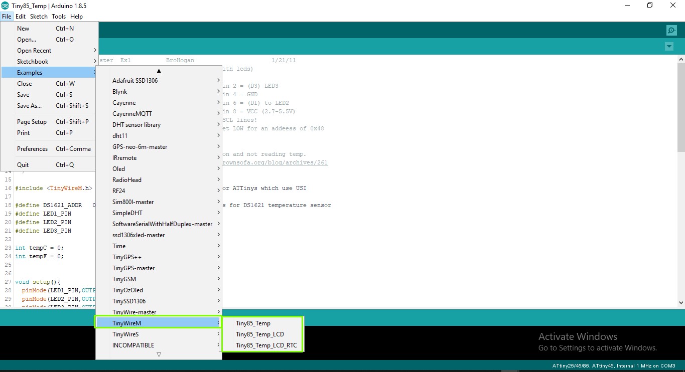
First i tried the Wire.h library that official given by the Arduino. But when compailing the wire.h library i got some error. So i googled and saw some answers from arduino forum that wire.h library wont work with attiny45 microcontrollers. As i xpected it happened. So now, i need to find another way. I searched for alternative arduino libaries that especially build for attiny microcontrollers. I found TinyWire.h library for arduino. The TinyWire.h library is build a for attiny microcontrollers. The library almost replicate the Wire.h. Visit the github repository for more info about the library.
Iam installed the library in my arduino IDE
Now i need to write the code for the master to turn on the LEDs of both master and slave while the button press by using I2C communication.
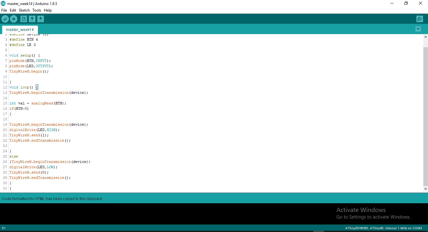
Arduino Code for Master
#include <TinyWireM.h>
#define device (1)
#define BTN 4
#define LE 3

void setup() {
pinMode(BTN,INPUT);
pinMode(LED,OUTPUT);
TinyWireM.begin();

}
void loop() {
TinyWireM.beginTransmission(device);

int val = analogRead(BTN);
if(BTN>0)
{

TinyWireM.beginTransmission(device);
digitalWrite(LED,HIGH);
TinyWireM.send(1);
TinyWireM.endTransmission();

}
else
{TinyWireM.beginTransmission(device);
digitalWrite(LED,LOW);
TinyWireM.send(0);
TinyWireM.endTransmission();
}
}
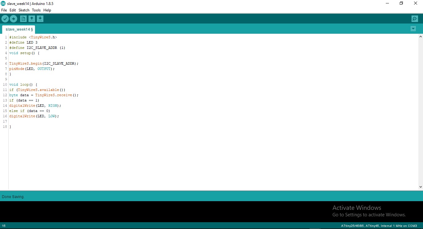
Arduino Code for Slave
#include <TinyWireS.h>
#define LED 3
#define I2C_SLAVE_ADDR (1)
void setup() {

TinyWireS.begin(I2C_SLAVE_ADDR);
pinMode(LED, OUTPUT);
}

void loop() {
if (TinyWireS.available())
byte data = TinyWireS.receive();
if (data == 1)
digitalWrite(LED, HIGH);
else if (data == 0)
digitalWrite(LED, LOW);

}
I uploaded the code to the master and slave boards. When i powered the board to by using the FabISP, i doesnt get the out put on the Slave board but the Master board is working fine. I go through code again and it is fine. Then i check ed the wiring of I2C bus, i was wrongly wired the I2C bus each other. I correct them and powered it again and Hola its working.