TODO LIST
- Group Assignment : compare as many tool options as possible
- Individual Assignment : write an application that interfaces with an input &/or output device that you made
Introduction
In this week we should need interface a microcontroller board with a PC or smartphone. Through interfacing the board with a computer, we can controll and monitor thedata. We have a lot of ways to do interfacing with the computer. Theere a lot of communication methods are used for interfacing the board with computer. The common methods is Serial communication. I choosed bluetooth communication to interfacing my board with android smartphone.
MIT app inventor
App Inventor for Android is an open-source web application originally provided by Google, and now maintained by the Massachusetts Institute of Technology (MIT).
It allows newcomers to computer programming to create software applications for the Android operating system (OS). It uses a graphical interface, very similar to Scratch and the StarLogo TNG user interface, which allows users to drag-and-drop visual objects to create an application that can run on Android devices. In creating App Inventor, Google drew upon significant prior research in educational computing, as well as work done within Google on online development environments.[1]
App Inventor and the projects on which it is based are informed by constructionist learning theories, which emphasizes that programming can be a vehicle for engaging powerful ideas through active learning. As such, it is part of an ongoing movement in computers and education that began with the work of Seymour Papert and the MIT Logo Group in the 1960s and has also manifested itself with Mitchel Resnick's work on Lego Mindstorms and StarLogo.[1][2]
MIT App Inventor is also supported with the Firebase Database extension. This allows people to store data on Google's firebase. Learn more

How does it works?
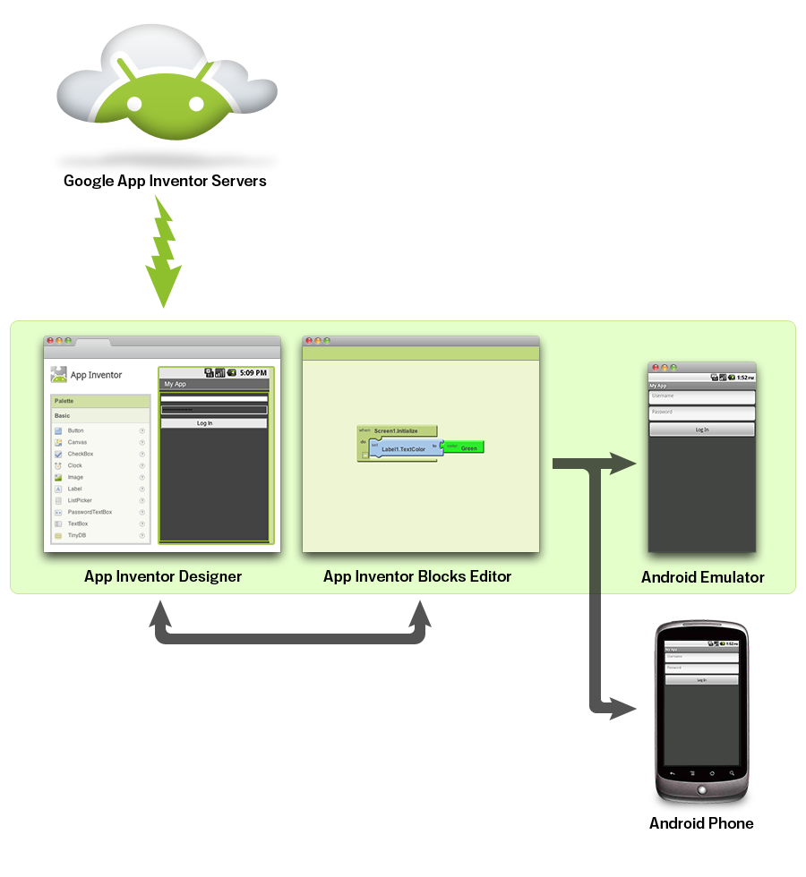
App inventor have two part
- The App Inventor Design Window, Designing the user interface and adding components.
- The App Inventor Blocks Editor, Programming the app by using blocks
Bluetooth Module: HC05
HC-05 Bluetooth Module HC‐05 module is an easy to use Bluetooth SPP (Serial Port Protocol) module,designed for transparent wireless serial connection setup.The HC-05 Bluetooth Module can be used in a Master or Slave configuration, making it a great solution for wireless communication.This serial port bluetooth module is fully qualified Bluetooth V2.0+EDR (Enhanced Data Rate) 3Mbps Modulation with complete 2.4GHz radio transceiver and baseband. It uses CSR Bluecore 04‐External single chip Rluetooth system with CMOS technology and with AFH (Adaptive Frequency Hopping Feature). Learn more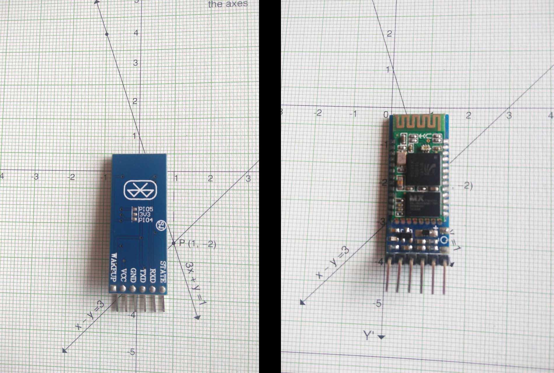
Hardware Features
- Typical ‐80dBm sensitivity.
- Up to +4dBm RF transmit power.
- 3.3 to 5 V I/O.
- PIO(Programmable Input/Output) control.
- UART interface with programmable baud rate.
- With integrated antenna.
- With edge connector.
- Software Features
Software Features
- Slave default Baud rate: 9600, Data bits:8, Stop bit:1,Parity:No parity.
- Auto‐connect to the last device on power as default.
- Permit pairing device to connect as default.
- Auto‐pairing PINCODE:”1234” as default.
Temperature sensor: LM35
The LM35 series are precision integrated-circuit temperature devices with an output voltage linearly-proportional to the Centigrade temperature. The LM35 device has an advantage over linear temperature sensors calibrated in Kelvin, as the user is not required to subtract a large constant voltage from the output to obtain convenient Centigrade scaling. The LM35 device does not require any external calibration or trimming to provide typical accuracies of ±¼°C at room temperature and ±¾°C over a full −55°C to 150°C temperature range. Lower cost is assured by trimming and calibration at the wafer level. The low-output impedance, linear output, and precise inherent calibration of the LM35 device makes interfacing to readout or control circuitry especially easy. The device is used with single power supplies, or with plus and minus supplies. As the LM35 device draws only 60 µA from the supply, it has very low self-heating of less than 0.1°C in still air. The LM35 device is rated to operate over a −55°C to 150°C temperature range, while the LM35C device is rated for a −40°C to 110°C range (−10° with improved accuracy). The LM35-series devices are available packaged in hermetic TO transistor packages, while the LM35C, LM35CA, and LM35D devices are available in the plastic TO-92 transistor package. The LM35D device is available in an 8-lead surface-mount small-outline package and a plastic TO-220 package. Learn more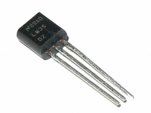
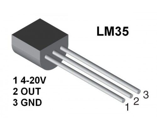
Features
- Calibrated Directly in Celsius (Centigrade)
- Linear + 10-mV/°C Scale Factor
- 0.5°C Ensured Accuracy (at 25°C)
- Rated for Full −55°C to 150°C Range
- Suitable for Remote Applications
- Low-Cost Due to Wafer-Level Trimming
- Operates From 4 V to 30 V
- Less Than 60-µA Current Drain
- Low Self-Heating, 0.08°C in Still Air
- Non-Linearity Only ±¼°C Typical
- Low-Impedance Output, 0.1 Ω for 1-mA Load
Designing & Making the PCB
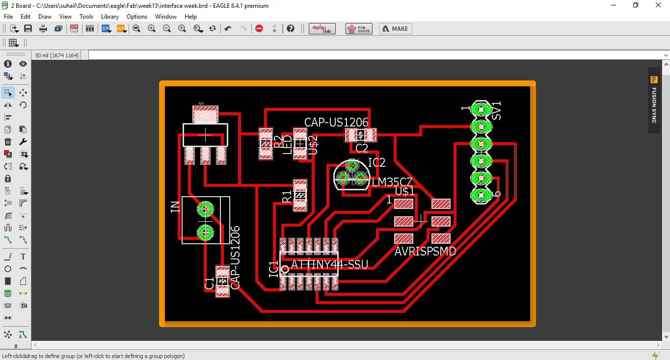
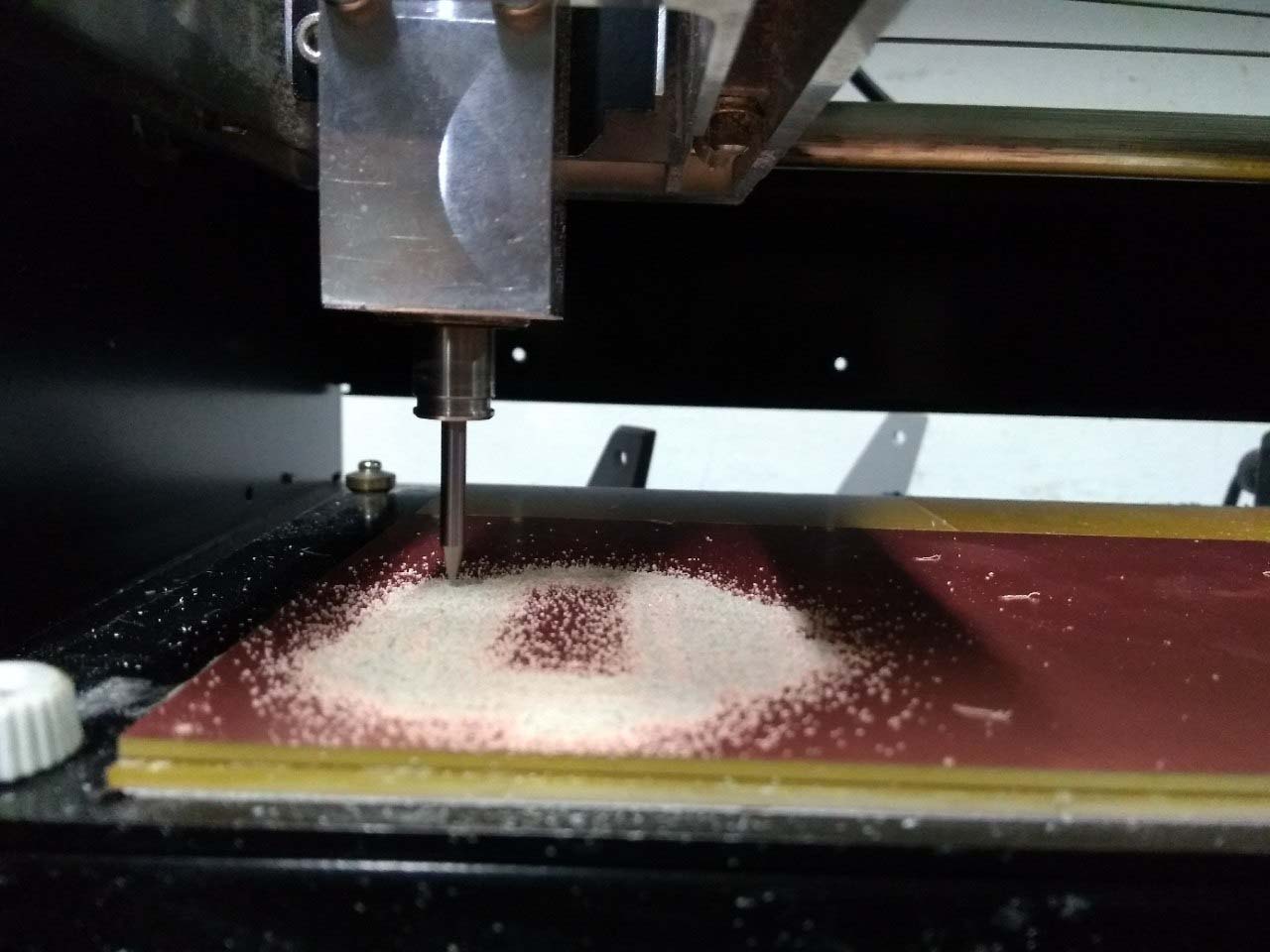
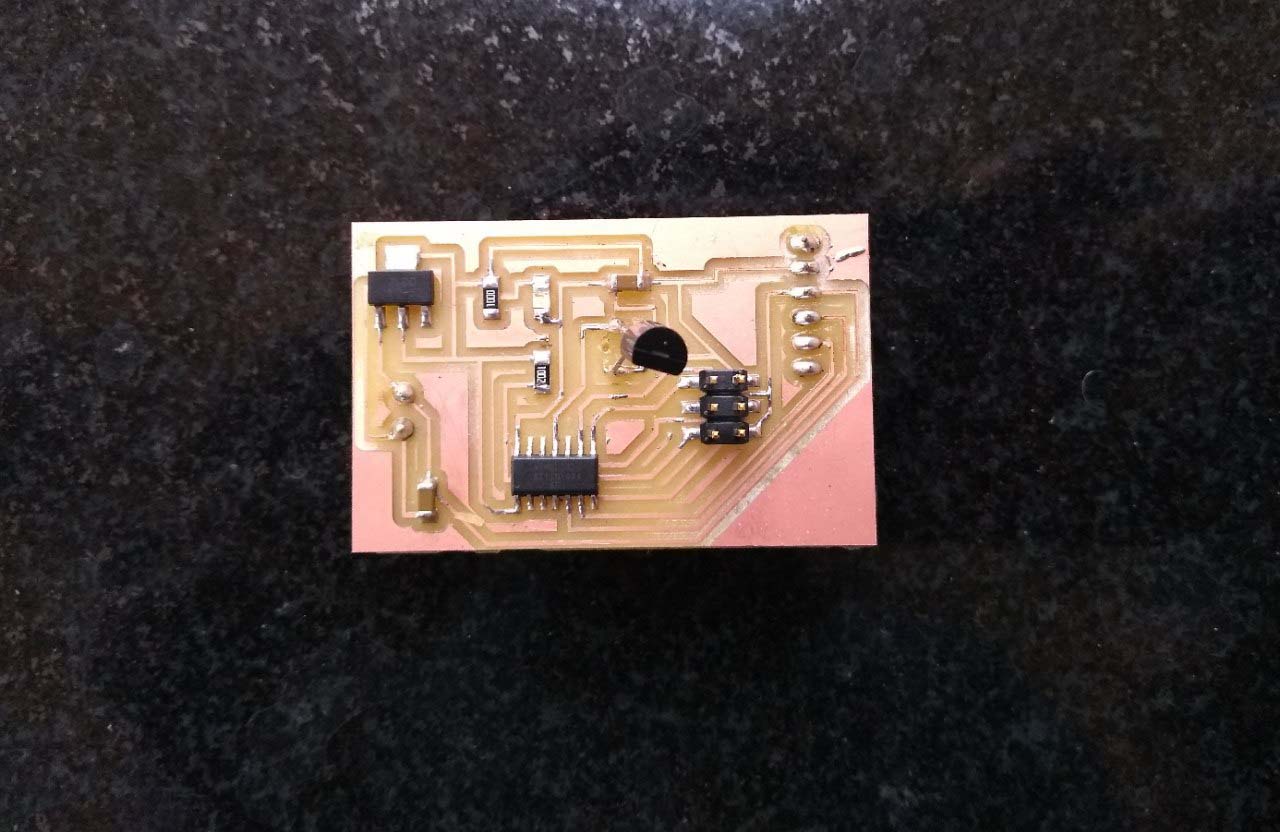
SO for this week i would like to make read temperature and send them to the androidphone vis bleutooth. I used HC05 Bluetooth module for this purpose. I used LM35 Analog temperature sensor for reading the temperature. I used Attiny44 as the microcontroller to make this project. I started to designing the PCB in eagle PCB. Then i milled the PCB using the Modella mdx20 PCB millingmachine.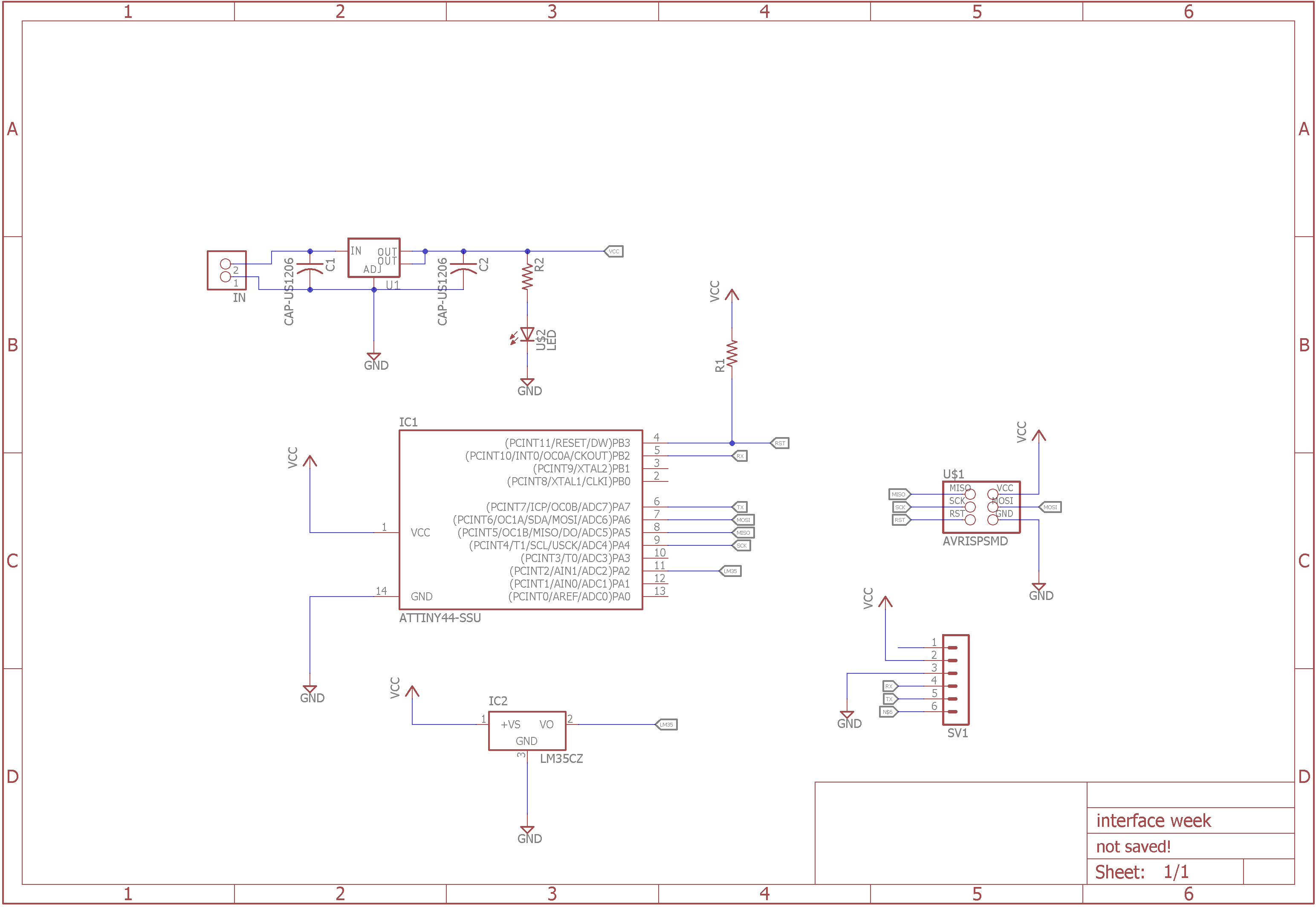
After that i soldered every components to the PCB. I soldered the LM35 in bottom side of the PCB becuase of on of the trace as been breaked. So i have only option to solder in bottom side(directly to the trace). After completing the soldering part i should test the powering of the circuit. I used a ZLDO 117 Variable voltage regulater for powering the circuit from any external source. The PCB is works perfect.
Programming the board: Arduino IDE
So now, i wrote the code for reading and converting into cecious of the the LM35 sensor data and send them via bluetooth. Then i selected the microcontroller that iam using (Attiny44) then upload the code using a FabISP. Here is the code below:
#include<SoftwareSerial.h>

#define RX PB2
#define TX PA7
SoftwareSerial serial(RX, TX);
int rslt;
float data;
void setup() {
  pinMode(A2, INPUT);

  serial.begin(9600);
}

void loop() {
  data = analogRead(A2);

  rslt = data * 0.48828125;
  serial.println(rslt);

  delay(1000);
}
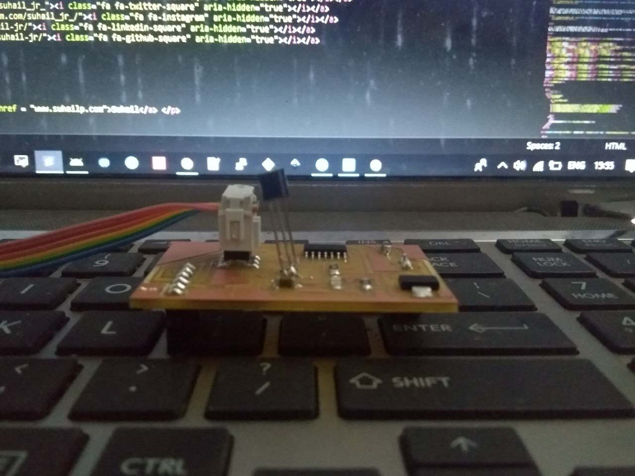
Testing the bluetooth communication: data recieving
So i uploaded the code. Before build a android application myself. First i need to make sure the bluetooth communication works correctly. I used a Bluetooth terminal app, downloaded and installed from playstore. You can find a bunch of bluetooth terminal app in playstore. Then i paired the android phone with the device. then open the terminal app and select the paired device. After i got the values printing in a console.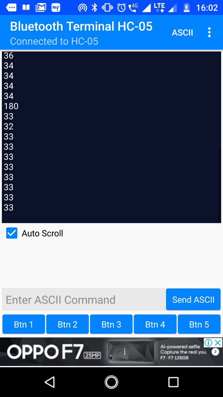
Building android application: MIT app inventor
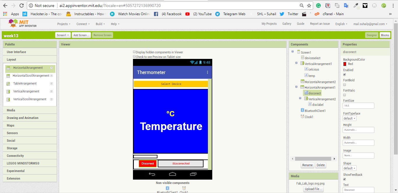
I started building a android application to display the data in android devices. i used MIT app inventor. MIT app inventor is too easy to learn and build an application. doesnt need to do coding all you need to do is drag and drope the components and blocks. I does not going into how i built the app it is so easy to use. If you are still confused then find the tutorials in HereFirst i added the basic componets that i wanted in the app. I used a List View componet to list all the Paired devices. I used horizontal and vertical layouts to place componets in a order. I used a Label for displaying the data coming from the device. A button for disconecting the device and a label to display the status of the device conection.
User Interface Design
Programming Block
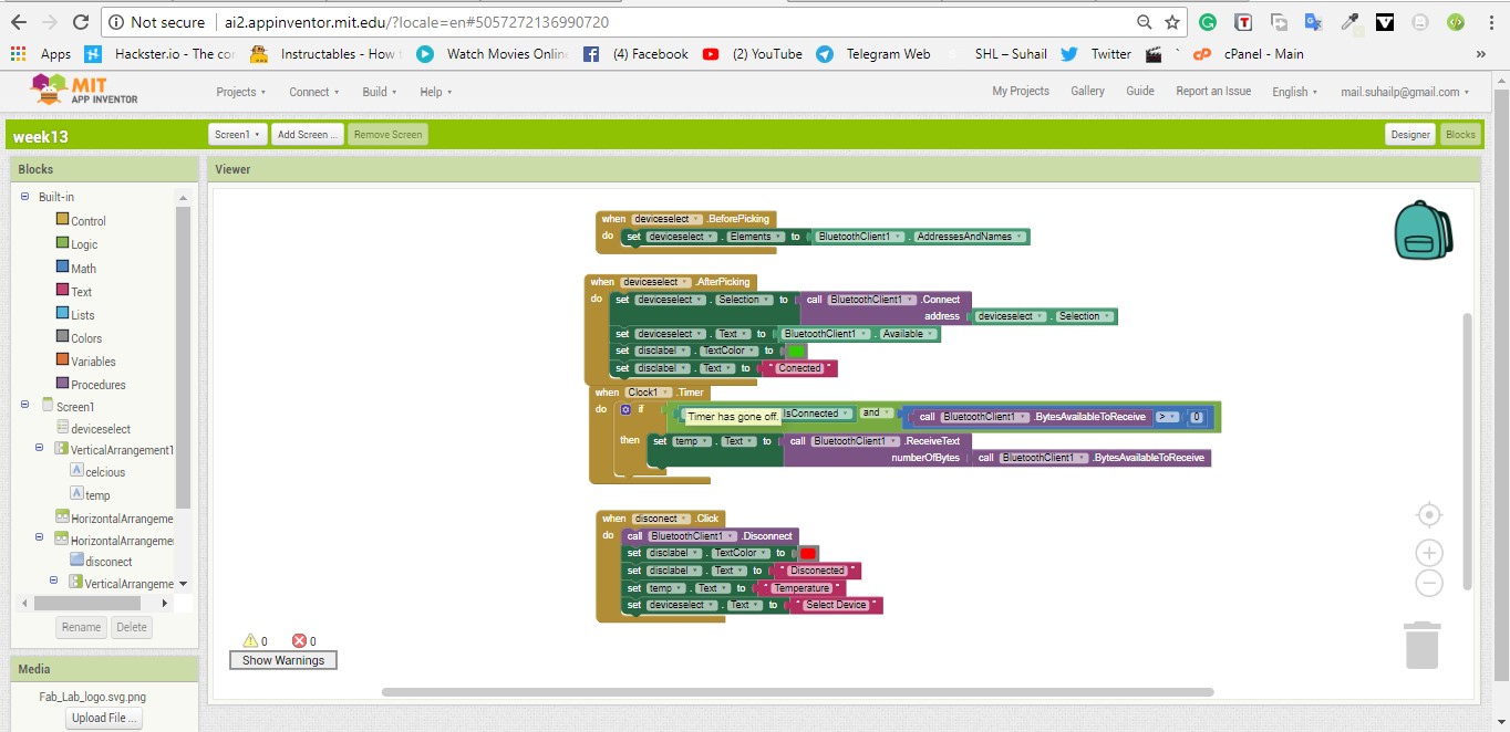
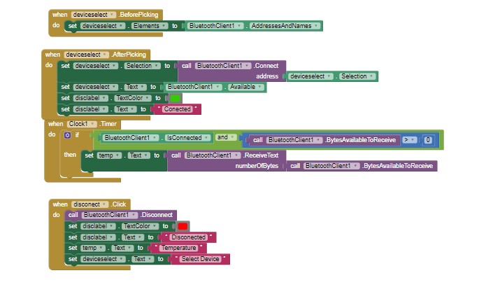
In the block designing, first i added the blocks to list all paired bluetooth devices. Then i added the blocks for picking the blutooth device that i need to select from the listview. After that i added the blocks for recieving the data from the bluetooth device and display them in the Label components. Atlast added the blocks for the button to disconect from the bluetooth device.
Bulding the APK
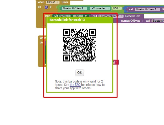
After designing the application i build the apk and send the apk file to my phone by scaning the QR code give by MIT appinventor. In the top of the Appinventor you can find the Build tab, hover over the Build tab and select Build app(provide QR code for APK). click on the option and the appinventor start to build the apk. After building the apk you should get QRcode in the screen. Scan the Qrcode with your android device and go to the link provided by the qrcode. Then download the apk and istall it in your device.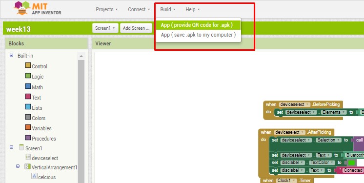
Lets Try Now
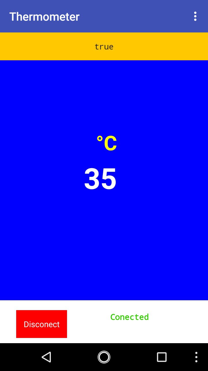
After installing the apk into my android phone. I open the application and selected the device(HC05). Then i waited a 2sec or less. Then the app started to recieving the data from the divice and display in the Label.