During these two weeks we are given the assignment to design and build a machine in the lab. This is a group assignment where we all combine our individual efforts to build the machine. Two whole weeks are given for the project. In the first week we plan and design a machine. The second week we build it. We decided to make an inventory managing machine that helps the user to easily pick the right component from the inventory.
I has started my contribution from the ideation stage. Together as a team we discussed ideas and came to a common consensus and proceeded to make a sorting machine. We were knowledgable in different areas. Some were good with design, some were good with electronics and programming and so on. I was more of a design guy. I helped developed the mechanical design of the machine. I used the knowledge i had gained in mechanical design tools to design the machine.The design was made in one single comuter jointly by members who volunteered to do join the mechanical design part.
The electronics part were taken care of by the other members of the team. I observed and learned from them. I could get more idea about the programming part as well.
Since the work was divided, I voluteered to take up the task of operating the milling machine and laser cutting machine. I also assisted in assembling the machine together.
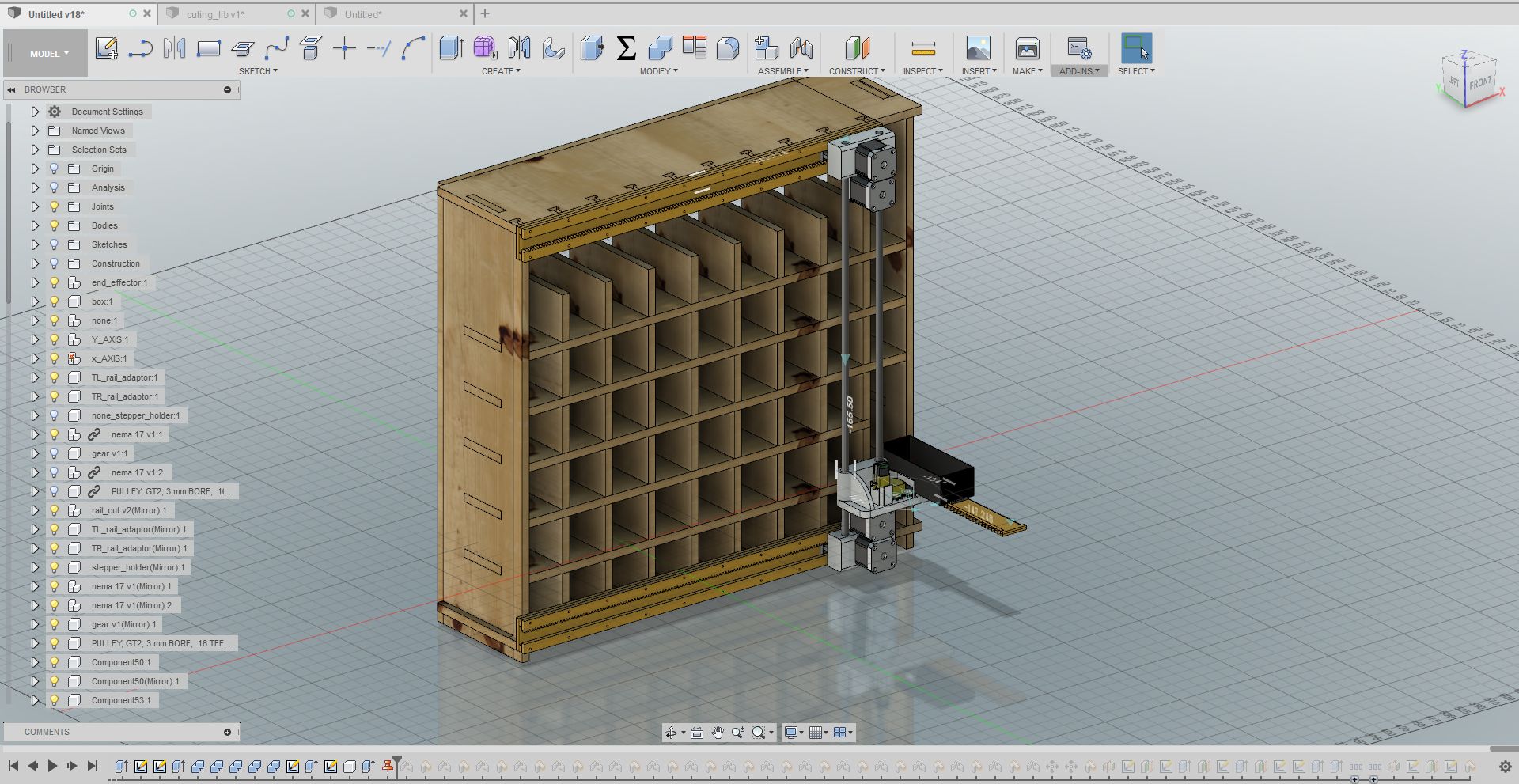
After deciding what machine to build we started the designing of the machine. The design was done using Fusion 360. Jogin Francis was the lead designer in the project. I contributed by suggesting ways to improve the effeciency of the machine and fabricating the components by laser cutting the rails and gears required for the project.
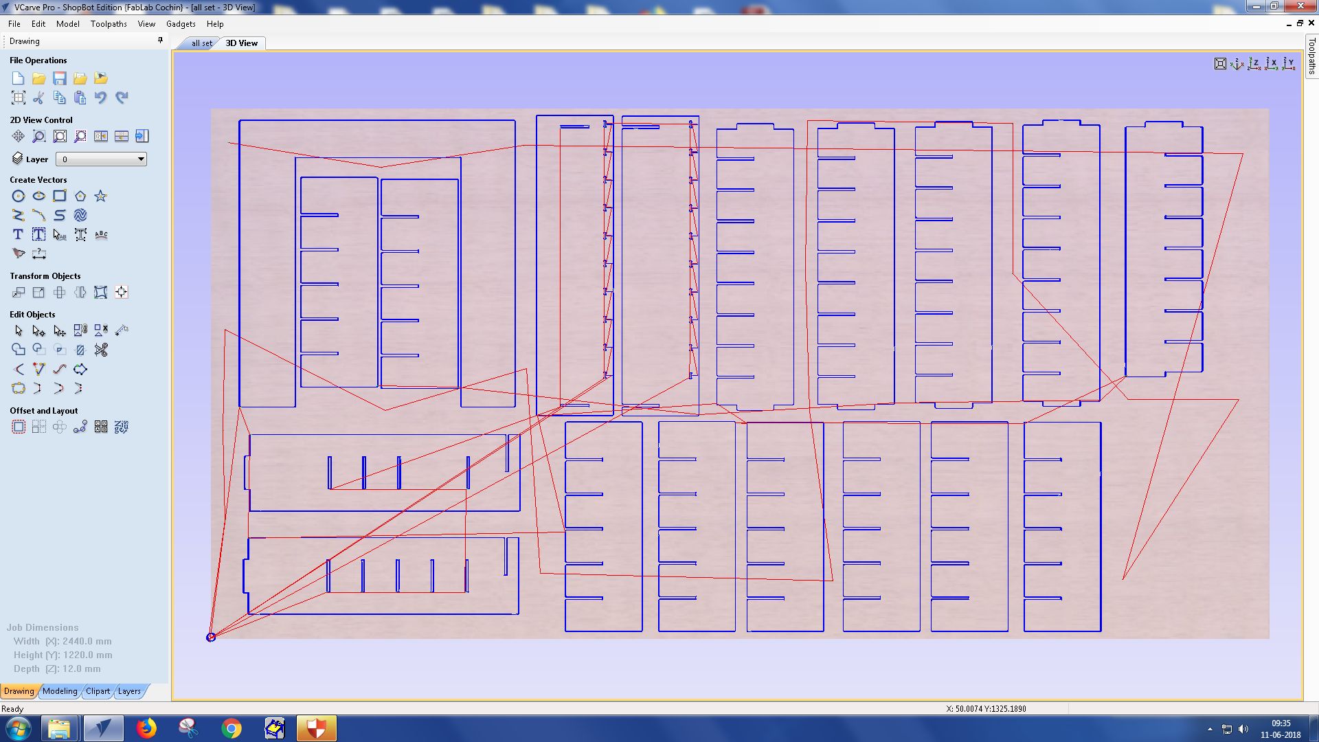
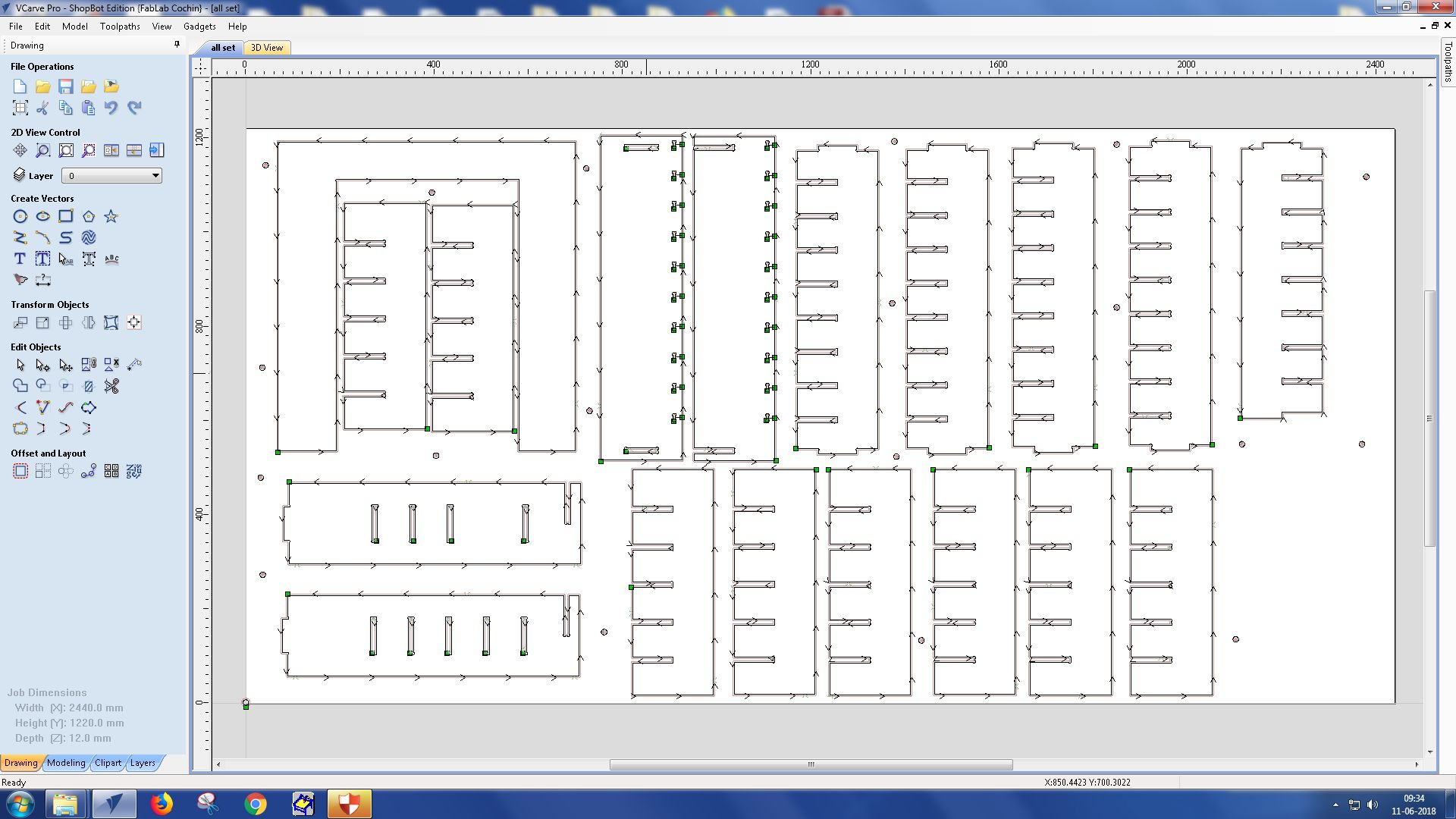
I also helped gather some items from the local market that was required for the fabrication of the machine. Later the shelf was to be made using CNC router. I took the design files in DXF format and with necessary arrangements in VCarve, the parts wer accurately cut out from the plywood.
The rails and gear required for the translatory motion was to be designed and cut. The design was made and was loaded for laser cutting.

The initial cut was a fail because some of the components were not cut properly. It didn't come out of the sheet after the cut.
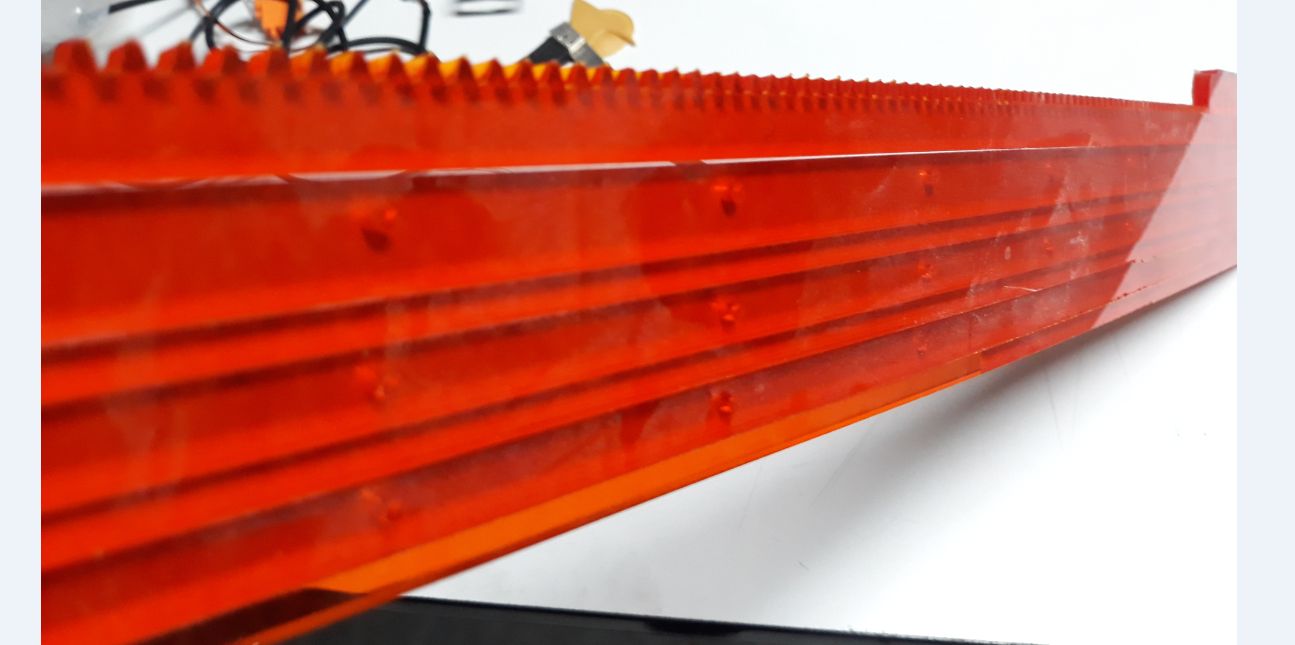
Later the power settings were adjusted and the cuts were made correctly
The components required for the machine were arranged neatly so that it fits in a plywood sheet. The cuts for the screw to pass through corectly had to be cut by selecting the on cut option. Also the bit was changed to 1/8" for cutting such small recesses.
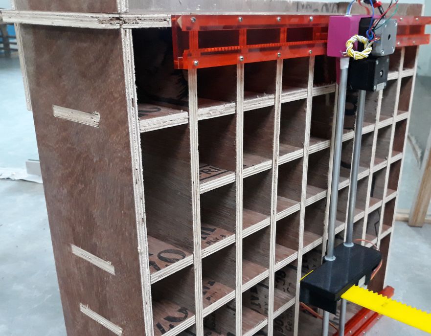
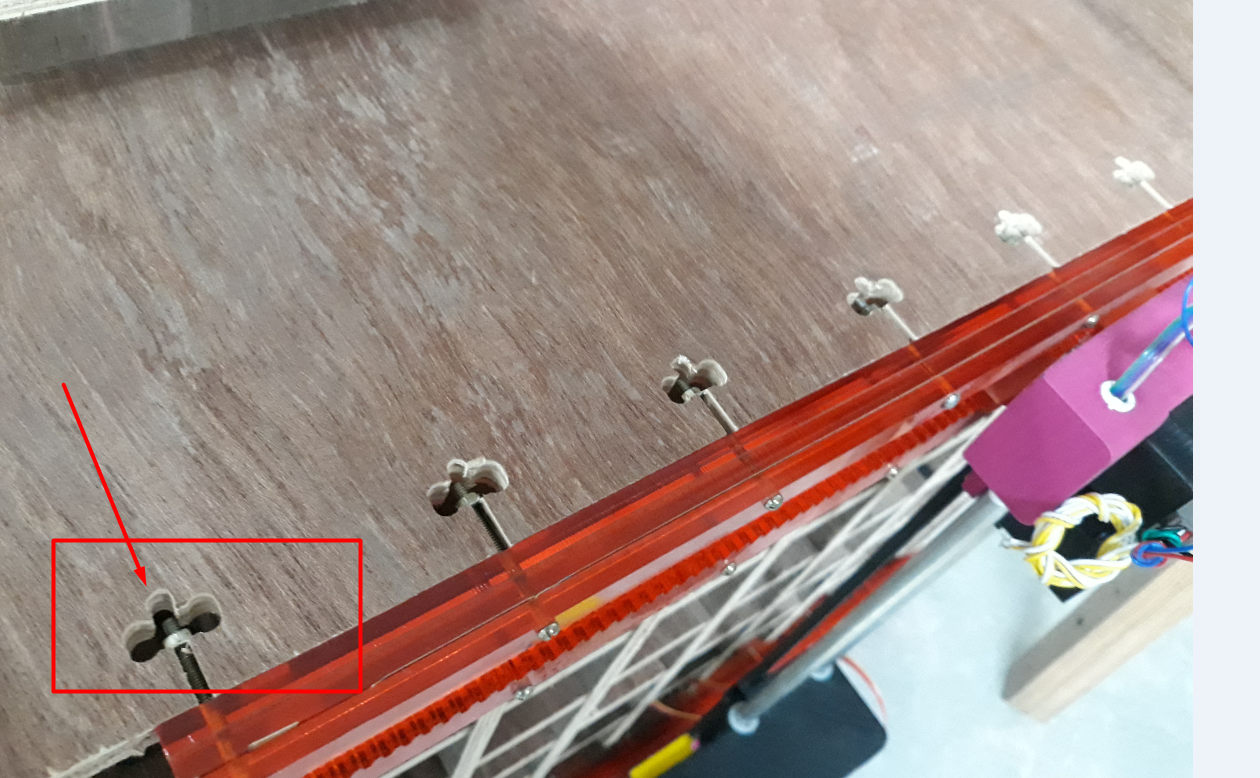
After cutting the machine components it was fitted together using screws. However due to slight miss calculation , the screws for fixing the rail to the machine did not fit correctly.
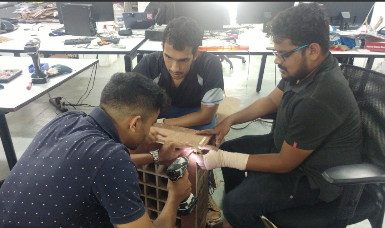
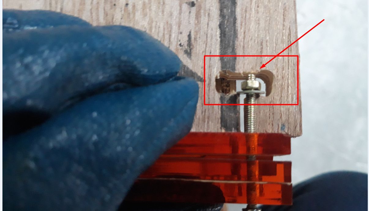
To fit the long screw correctly, more space was needed and for that we drilled a new hole near it.
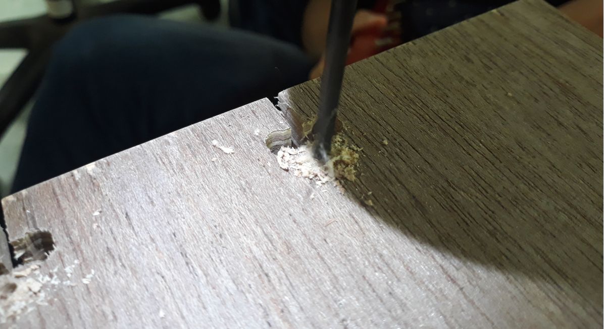
Drilling the hole was a successful attempt. The screws now fit in correctly.
The elctronics parts of the machine was done by the other team members. I learned about programmming from them. I assisted them in the making and observed its working clearly.