

As we know that
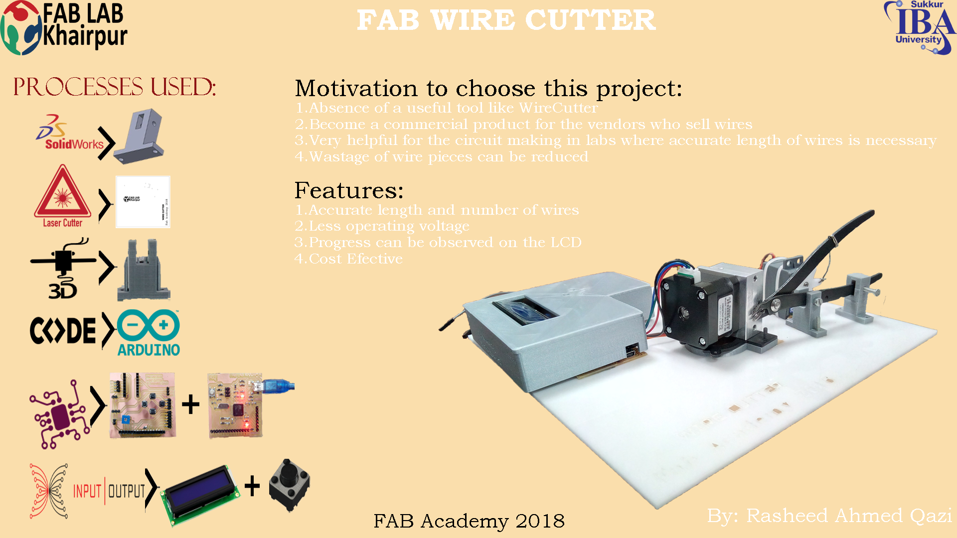
The project comprises of following main parts:
First of all , I chalked out a plan and strategy for completing the final project. I moved step by ste[ , from one module to the other. Initially, I studied about the existing wire cutter projects, in this way I got a complete insight of what I will be needing in my project and which things will take more time.Following are the main parts of my project defined in detail .
In my project I needed to make some 3D printed parts and a Laser Cut Base part. I chose to work on Solidworks , because of the main feature of parametric Designing. I made some model using parametric design in my earlier assignments for Laser cut and CNC. Now, I am really liking this CAD tool so much, as it is easy to handle and provides you the opportunity to check the assembly of different parts you made.
First, I started with Base designing, and I used following tools:
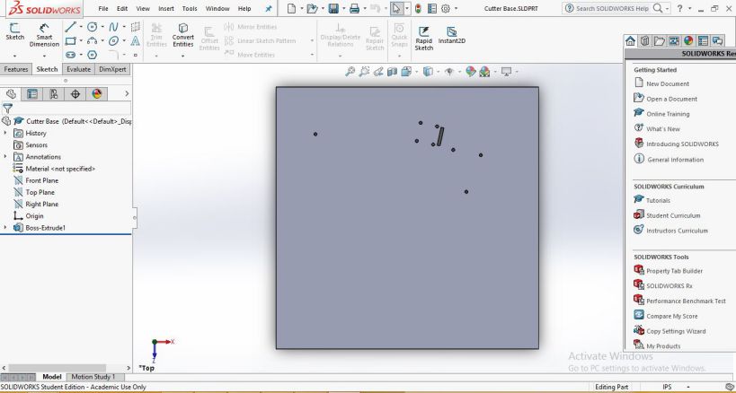
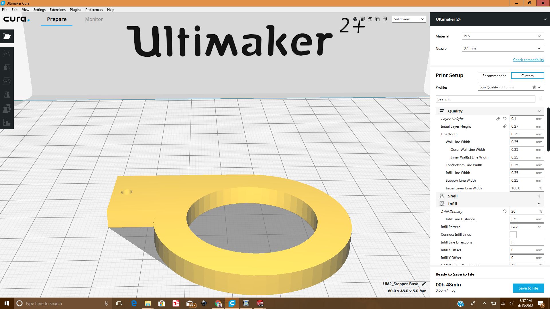
3D Design of Base for Wire Cutter
The stepper Base was made to put the gap between stepper motor and acrylic sheet
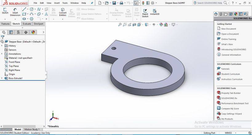
3D design for Stepper base
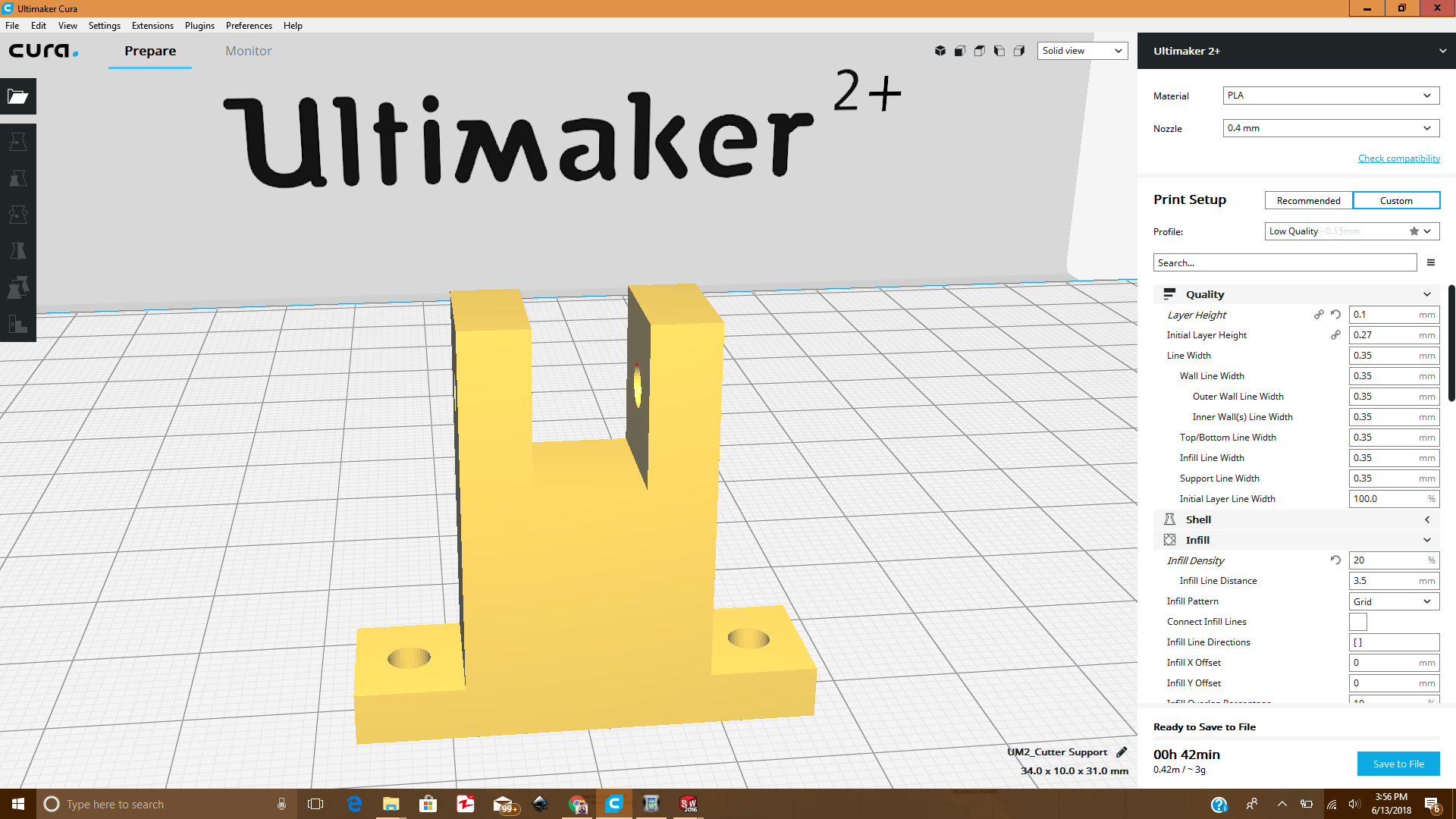
This part is designed to give support to hold the Cutter firmly in a position. Two pieces are designed for holding the wire cutter.
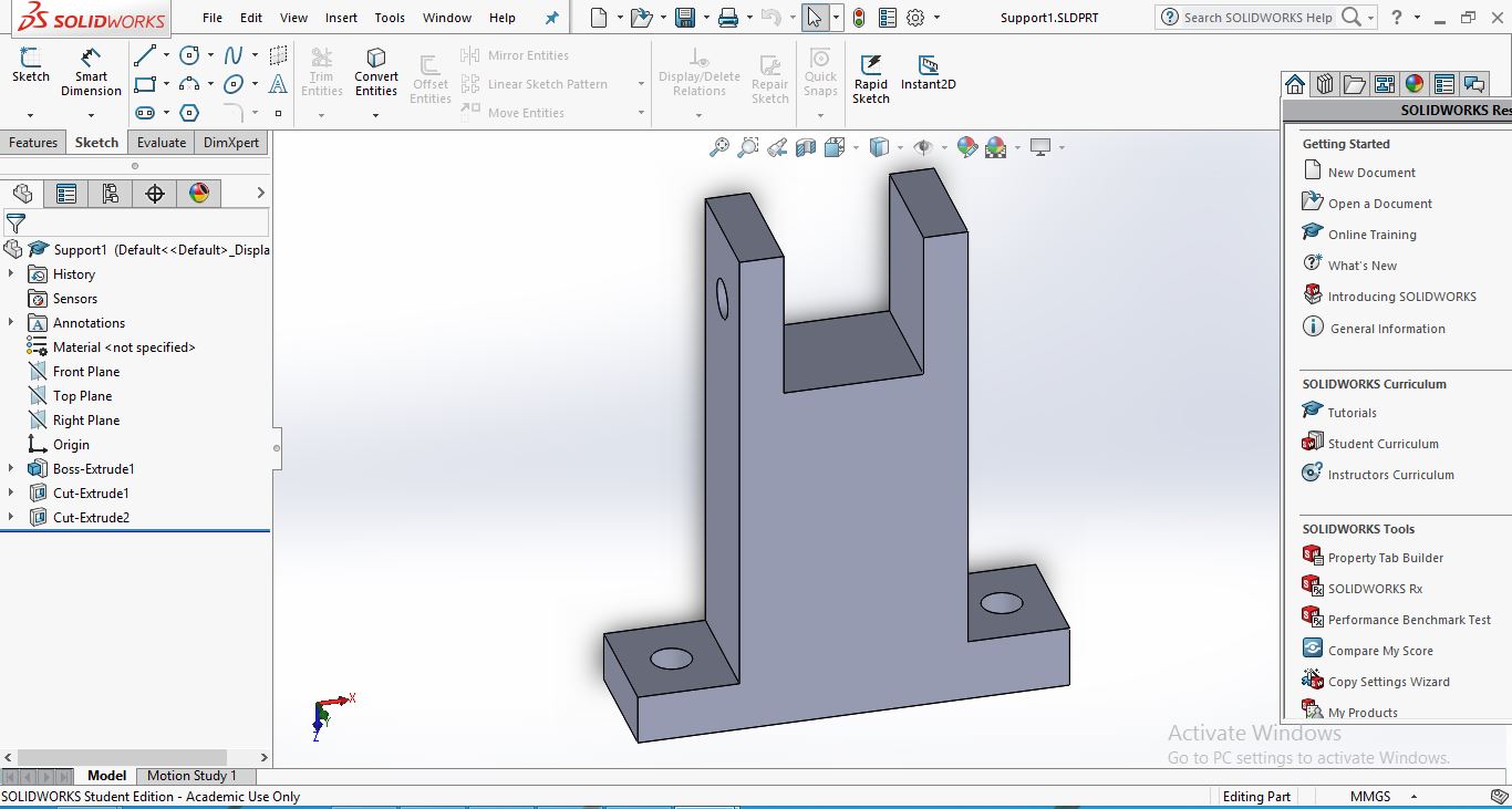
3D design for support
After designing the parts in Solidworks , I created the .STL file from the.SLDPRT for printing in Ultimaker CUra software.
3D Print of Stepper Base part
3D Print of Support part
The Laser cut design was made in Solidworks, and then the .sldprt file was saved as a .dxf file. Then, I opened the file in inkscape . For Laser cut we have to do some settings in inkscape like setting the stroke style for laser cut.
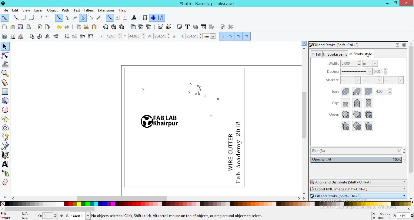
The wire cutter base in Inkscape
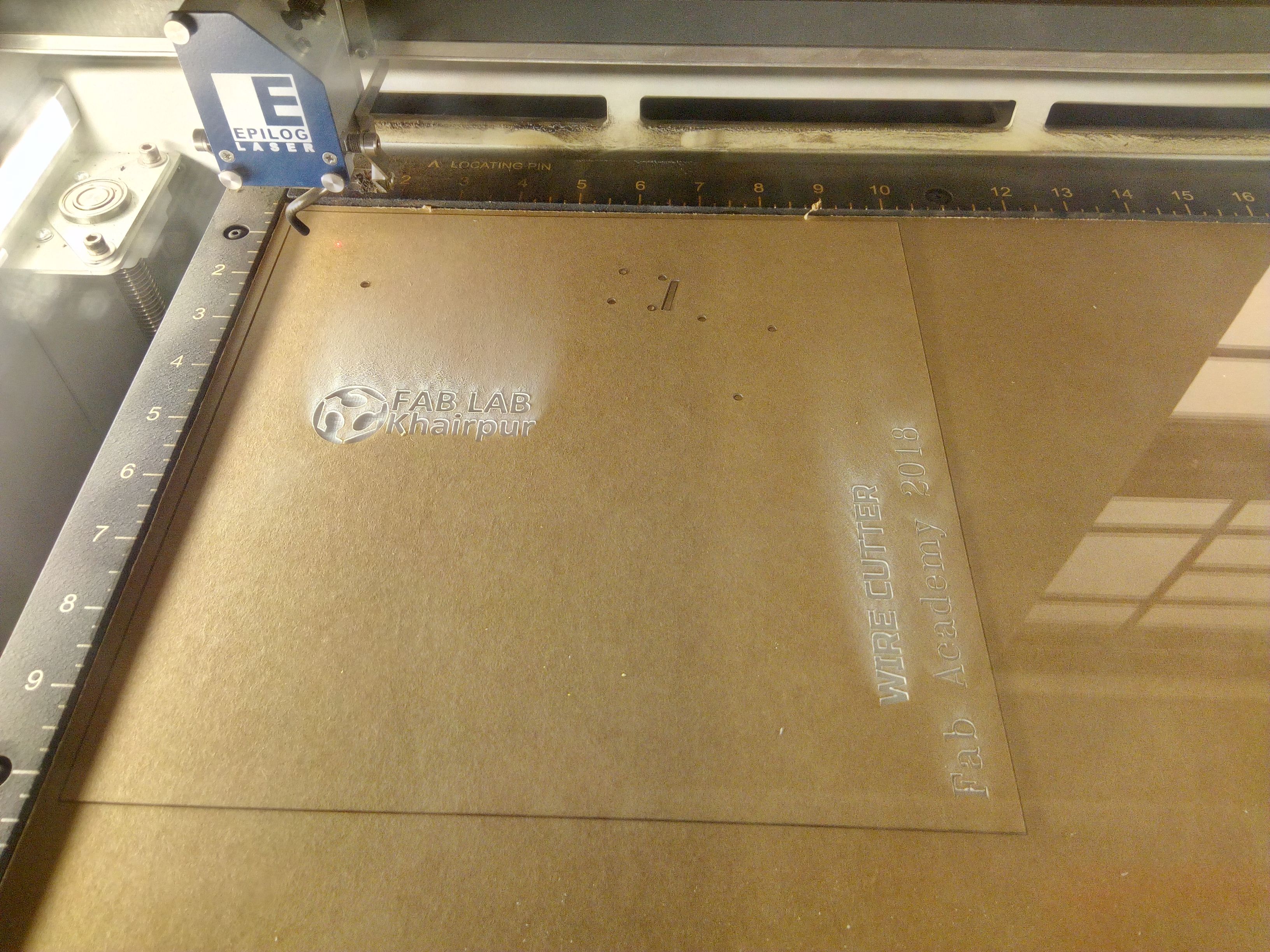
The Base of wire cutter on job
The main part of my project is to design the main PCB board for wire cutter to control the whole circuitry including input output and the other main parts like servo , stepper and the extruder. I searched for some PCB layouts then worked on the Eagle software to make the PCB. We have been making the bords since the very start, so it was not a dificult thing, but even then I had to be careful in designing the circuit. I had to keep following things in mind before designing the board.
First I made the circuit on Breadboard for testing purpose.
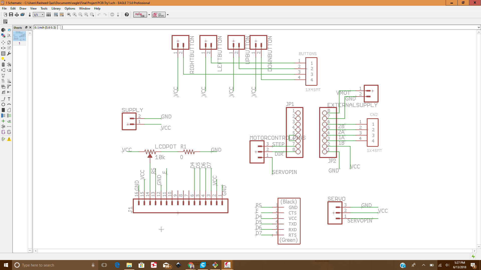
The arduino Leonardoschematic in Eagle
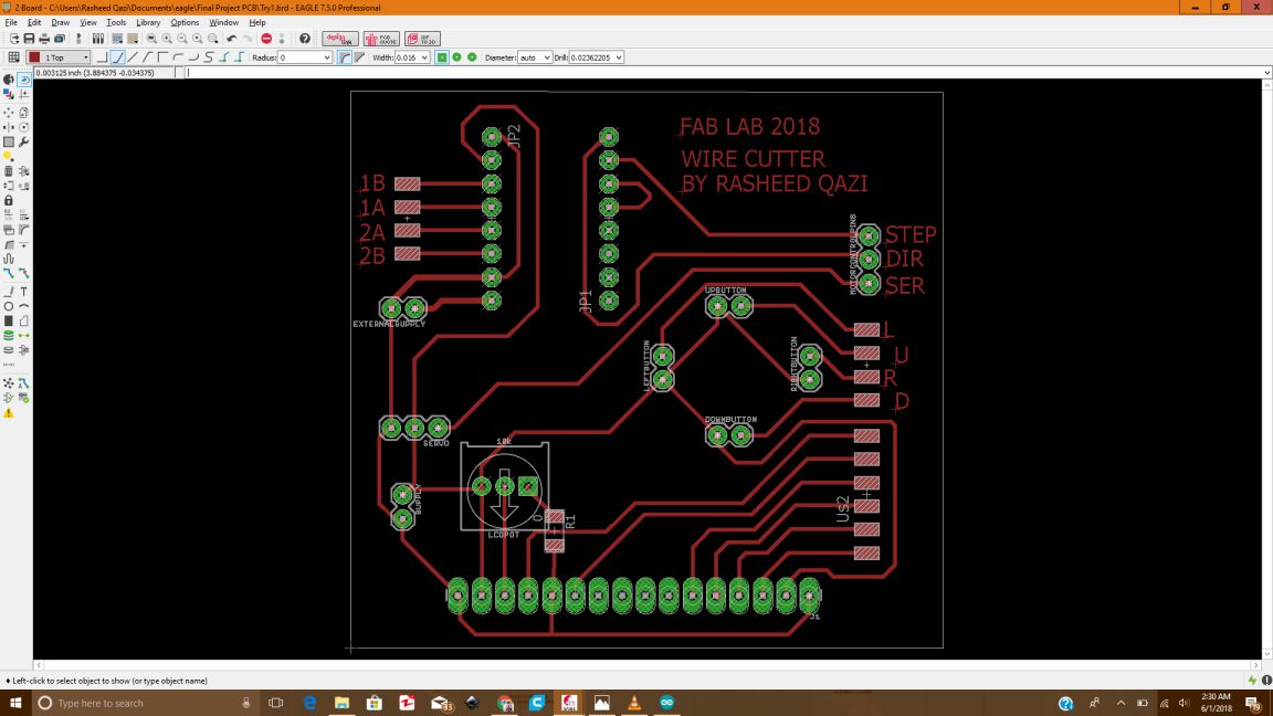
The Board made in Eagle for Wire Cutter
After making the board, I exported and saved the board file as .PNG file , so that I can edit it and generate the RML files for milling on Rolland SRM-20.
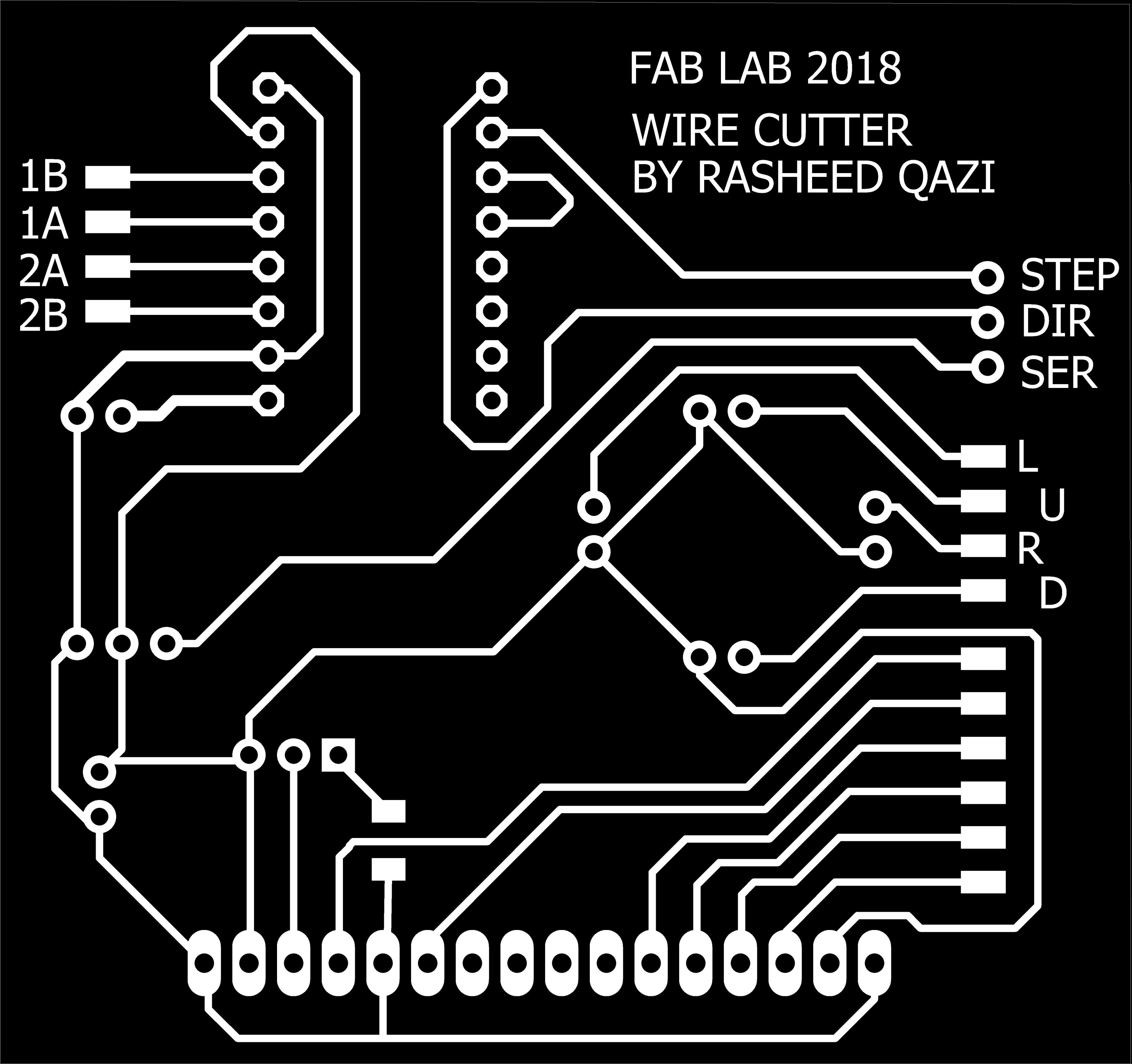
The Board saved as .png and edited for generating RML of Traces


The Drills and Outline png files
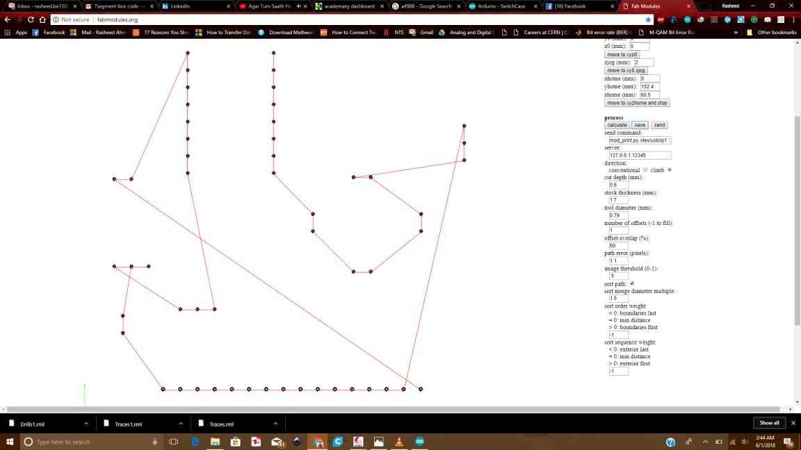
Now, the next step was to generate the rml files using the < a href= "http://fabmodules.org/">Fabmodules.org
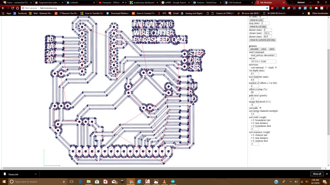
The RML file for traces generated in fabmodules
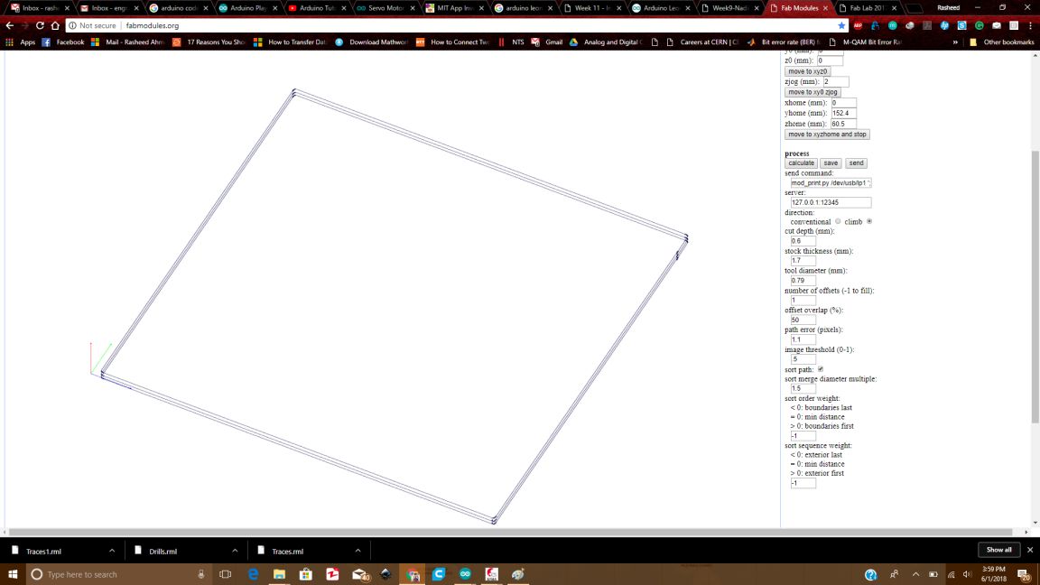
The Drills and Outline rml files
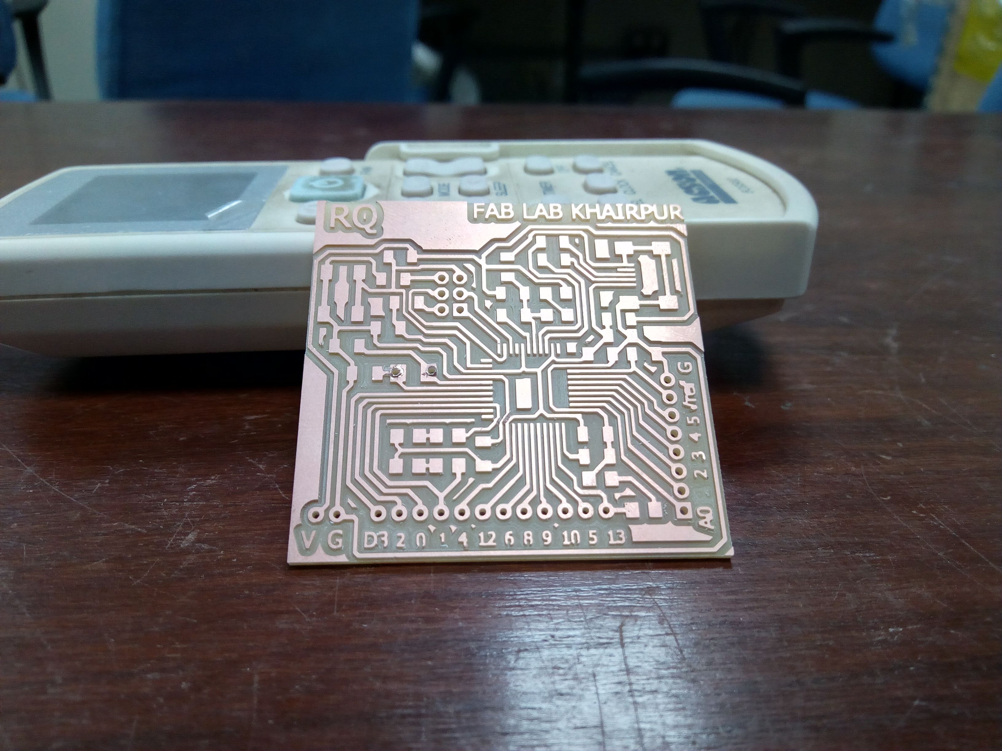
Now using the tolls for Traces(1/64) and Drill and Outline with 1/32, the board was milled.The board after milling is shown below:
Then, I made the list of required components for slodering and as I am already good at soldering the components, so it took me very little time to ready the circuit for burning the bootloader in it , so that I can move to the next part of programing the board and check whether the input output and other components are being controlled through programming.
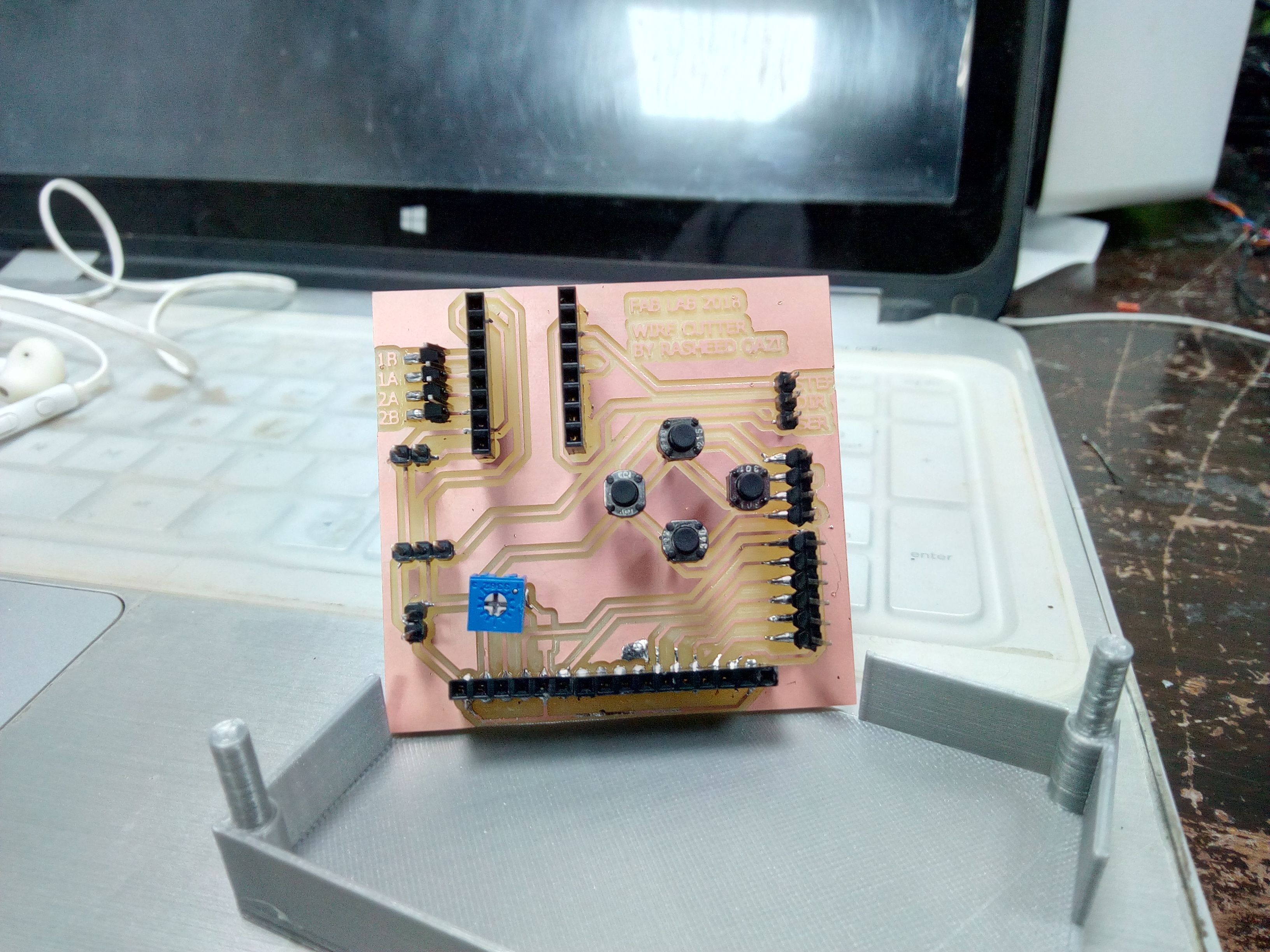
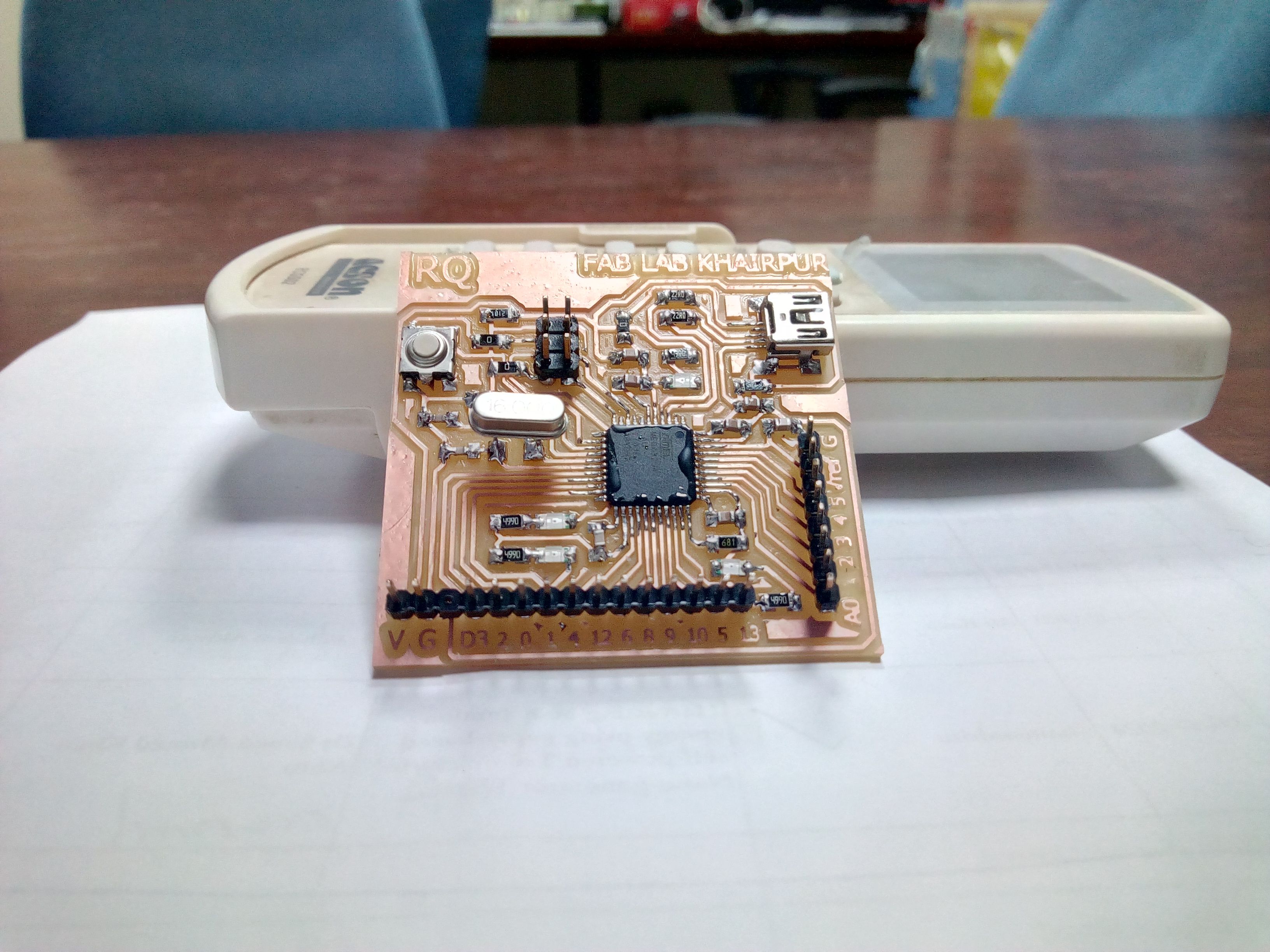
The wire cutter circuit is ready after soldering
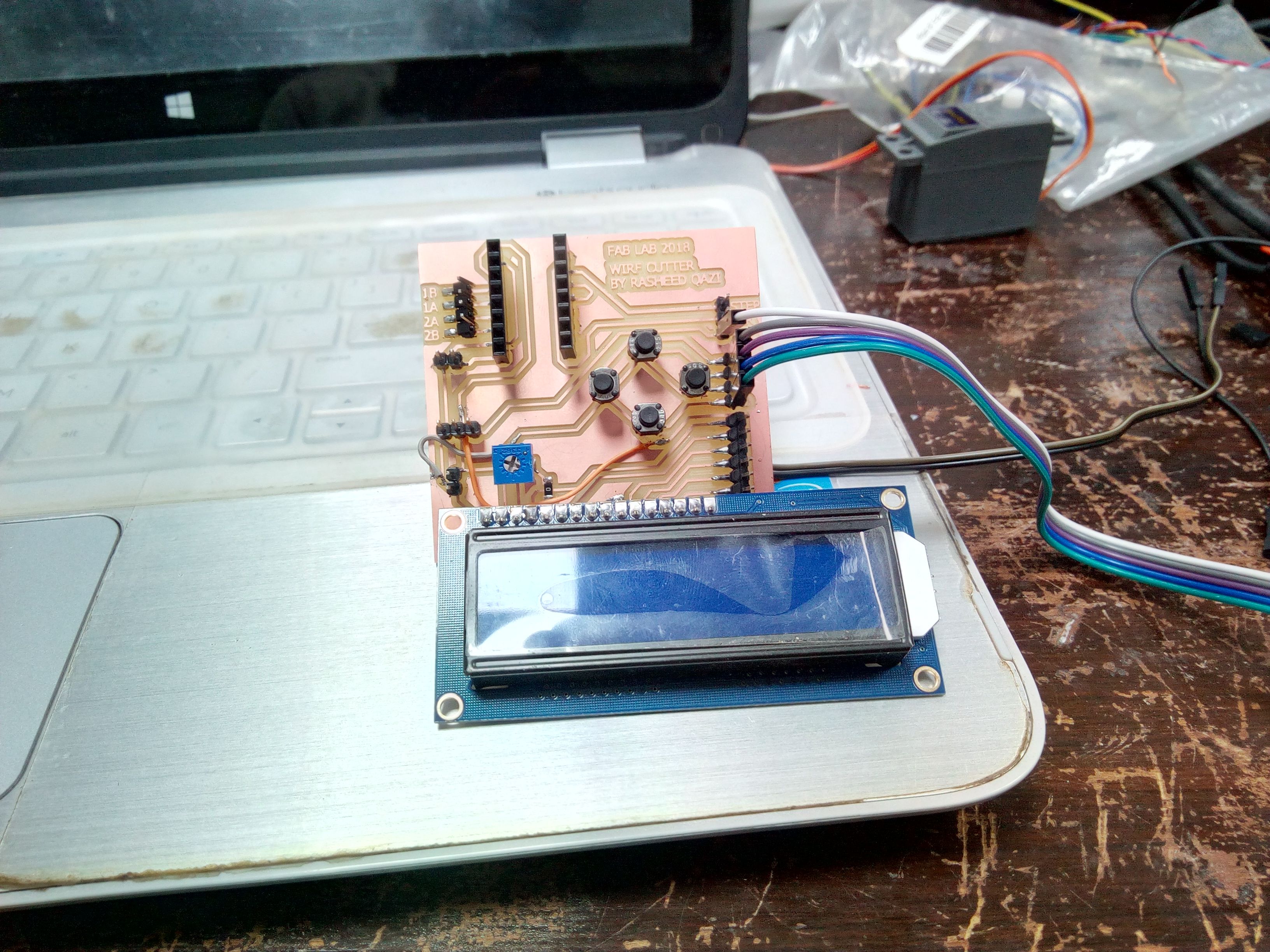
The wire cutter circuit with its input (push buttons) and output (lcd)
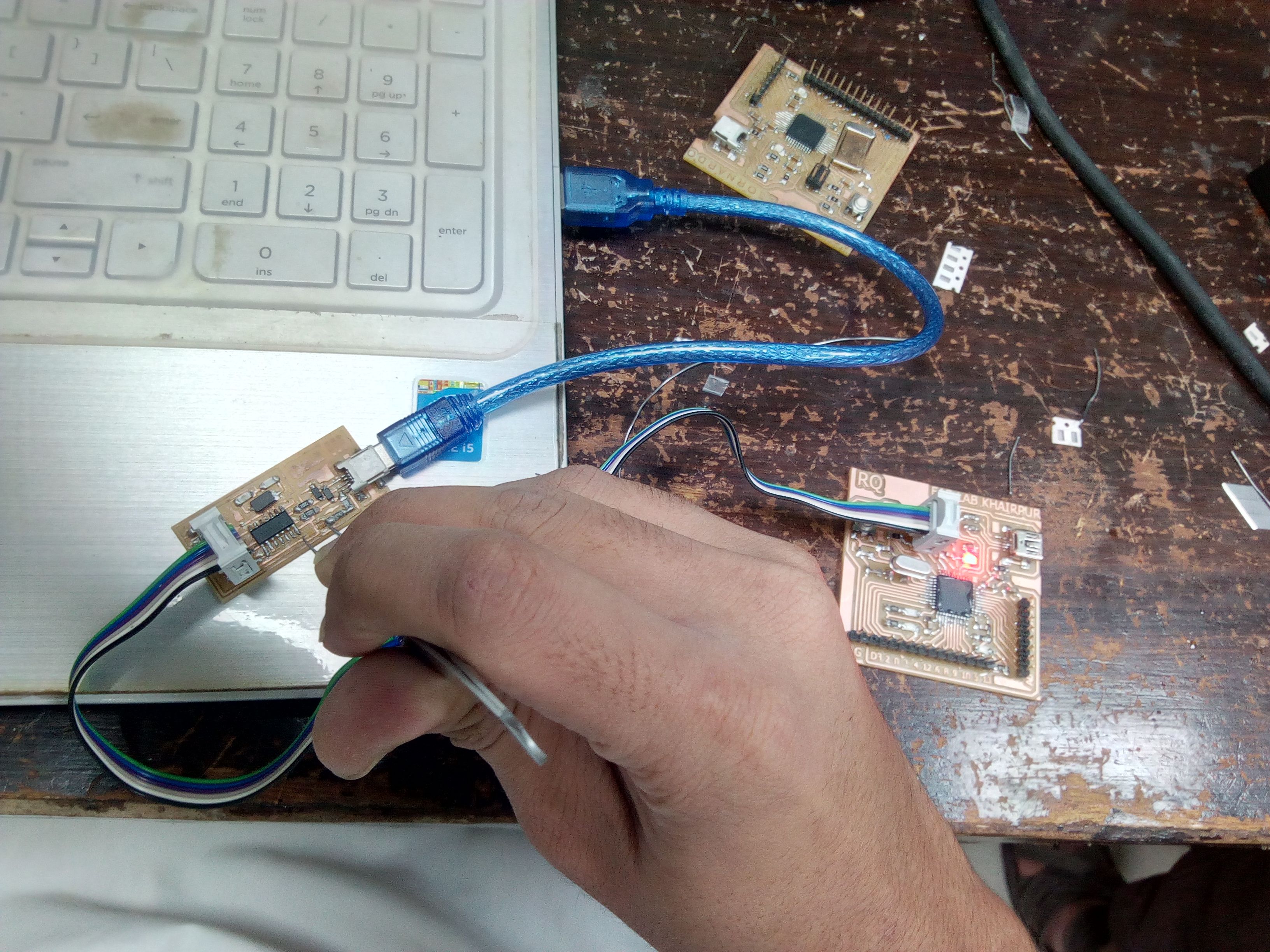
Then I made the Arduino Leonardo board, which is the central processign unit for my project. It read the input from the buttons, and checks for he conditions and states and then switches the display on the LCD screen so that it looks like a new screen every time. The following images show how I made the leonardo board.I checked some layouts in iternet and I redesigned the fab leonardo circuit.
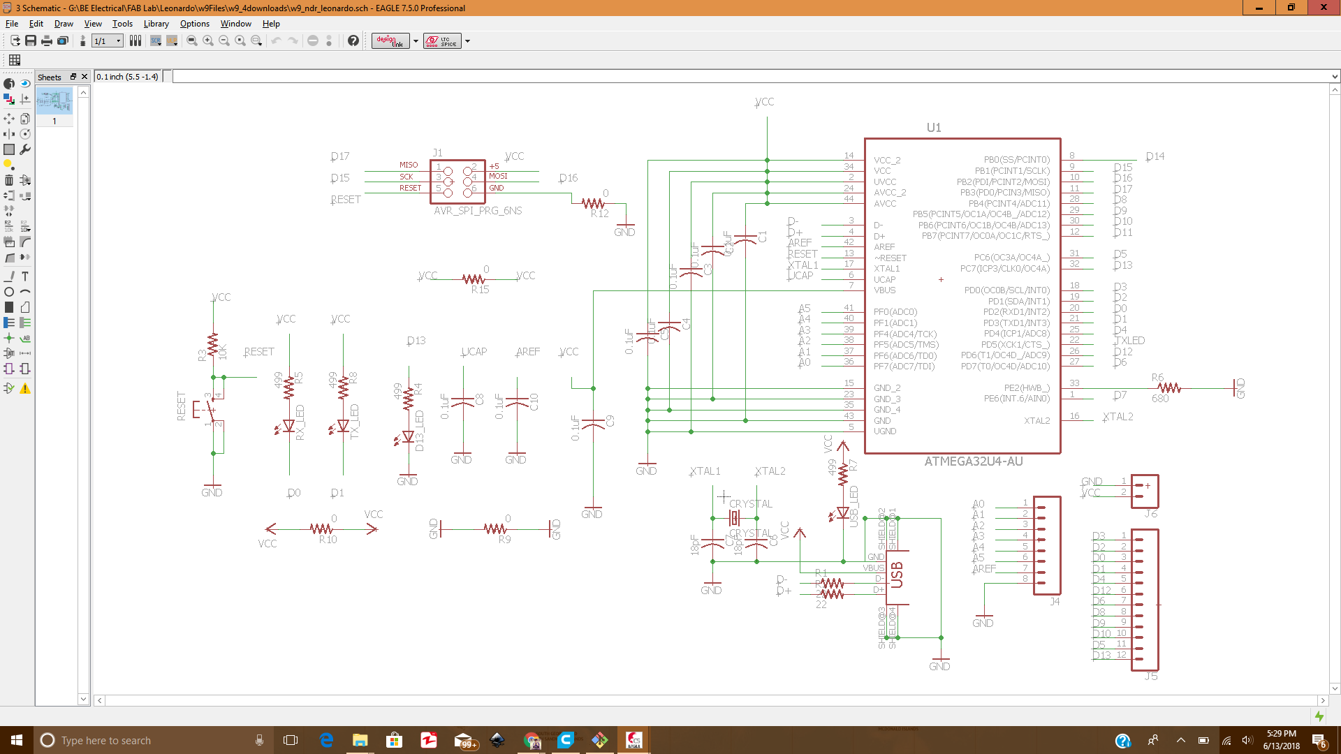
The arduino Leonardo schematic in Eagle
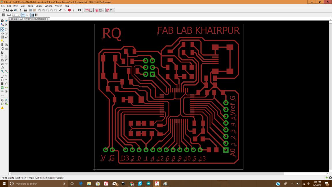
The arduino Leonardo board in Eagle
Then , I exported the board file as .PNG and then edited it in paint. The png files were used to generate the RML.
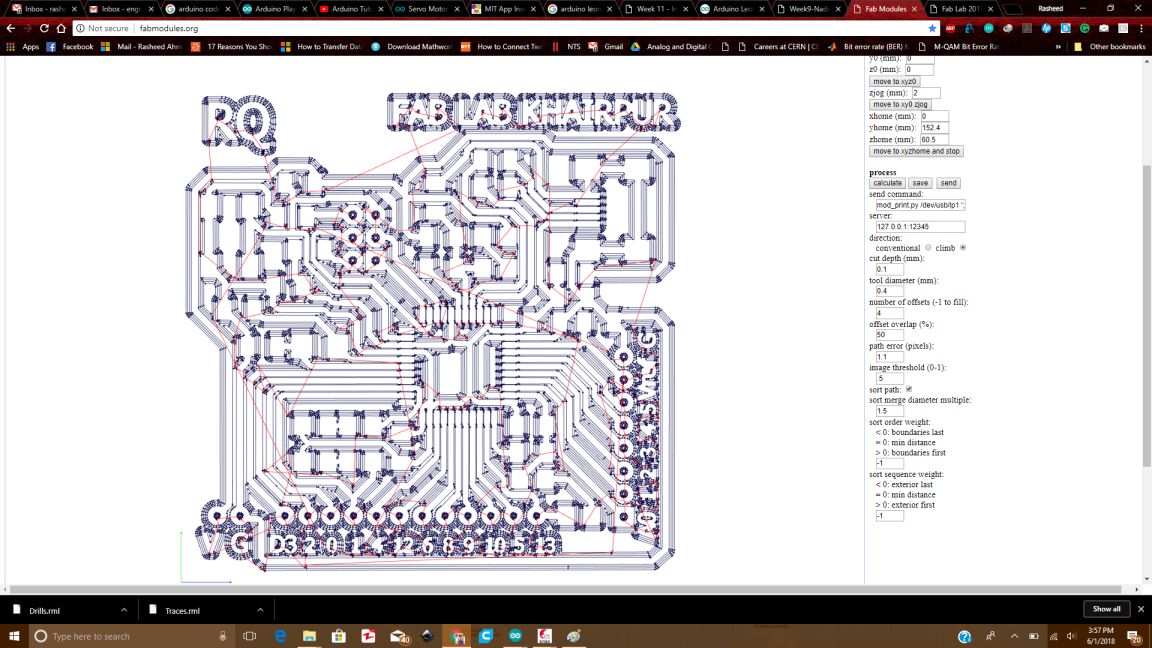
The RML file for traces generated in fabmodules
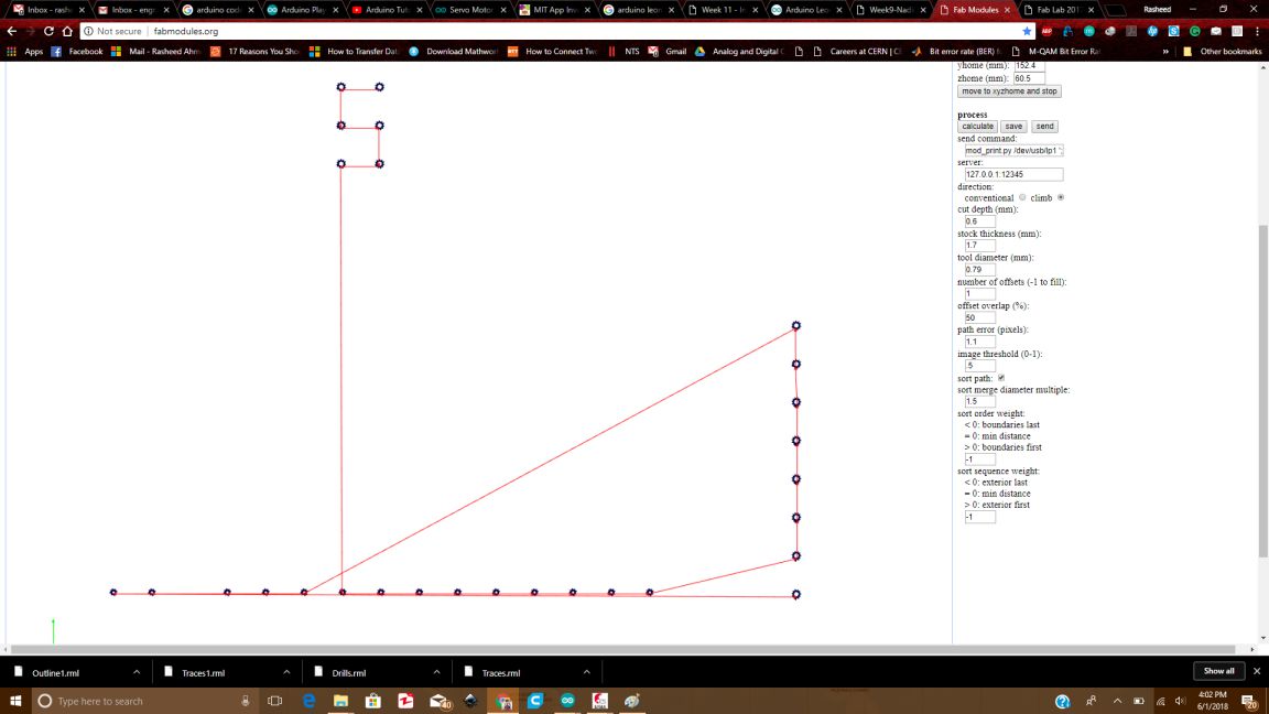
The Drills and Outline rml files
The Leonardo board was mille din Rolland SMR-20 , using the 1/64 tool for making traces and 1/32 tool for making the outline .
The Leonardo board milled in Rolland SRM-20
The Leonardo board soldered
Initially when we were connecting the circuit , the extruder was not working fine, and it was not moving in any particular direction, it produced a sound like its gears were rubbing against each other. Then, we changed the stepper motor. After we replaced the motor , the new one was working quite well, with no noise at all.
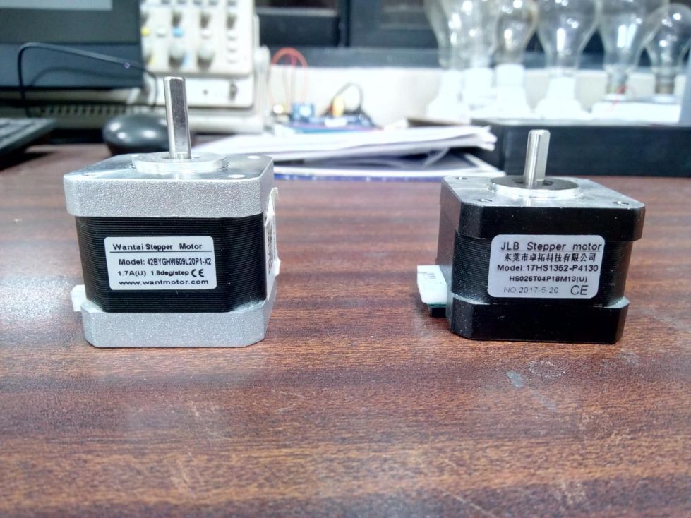
The stepper motor is replaced
Initially , when the motor was not working properly, the IC aslo heated up. The heating caused the two ICs to be burnt. So, to rsolve this issue, I removed the IC from the input/output circuit and checked. This time, the IC worked fine; no heating and no noise at all.
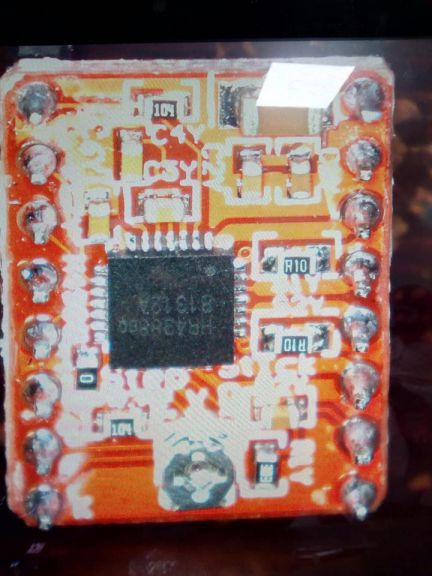
Stepper motor driver IC (A4988)
So, I decided to make my own stepper driver IC, I checked some layots on internet and came up with the following design.I made the circuit in Eagle.
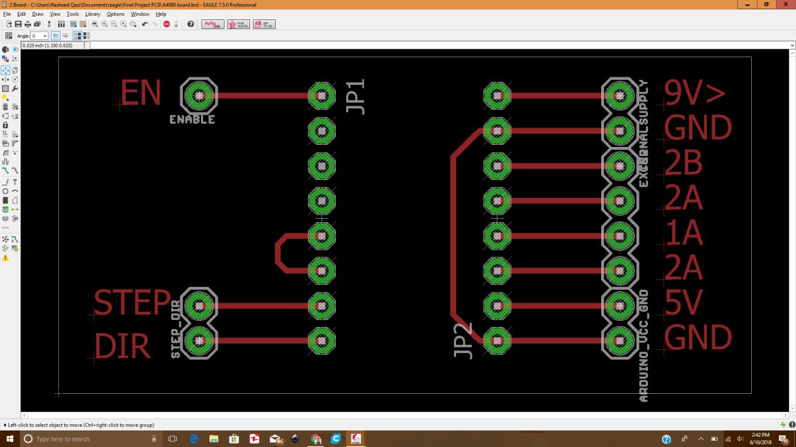
Stepper motor driver IC (A4988) board file in Eagle
After checking for the errors, I exported the file as a PNG and edited in paint.
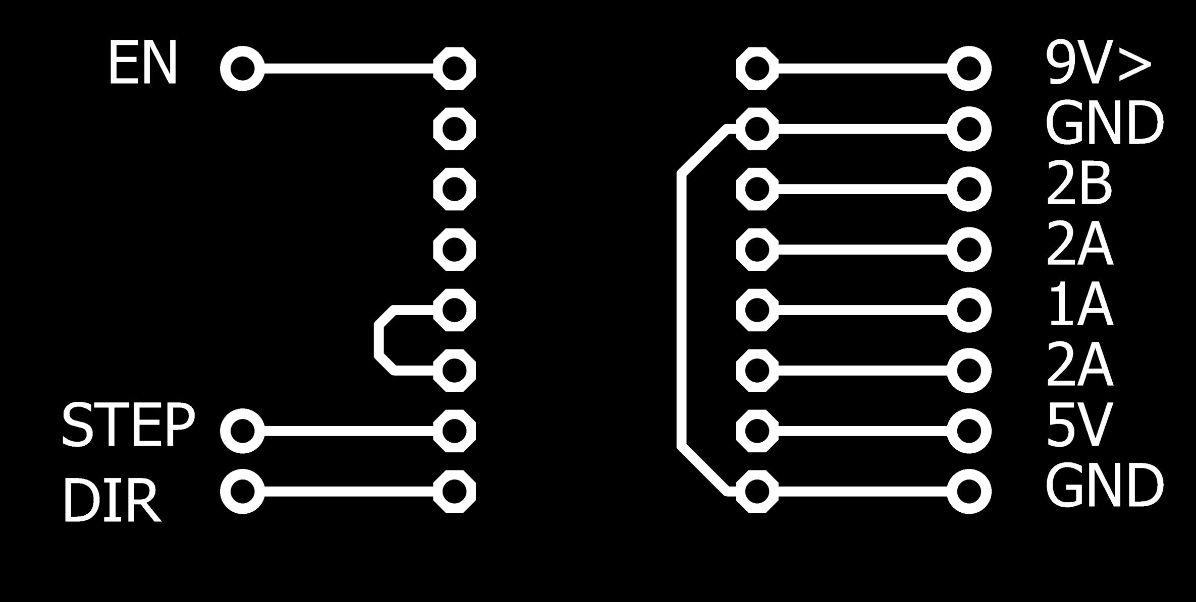
Traces for Stepper motor driver IC (A4988) edited in paint
Now, it was time to generate the rml files using the fabmodules.org The rml images are shown below:
.jpg)
RML of Traces for Stepper motor driver IC (A4988) using 1/64 tool size
.jpg)
.jpg)
RML of Outline and Drill for Stepper motor driver IC (A4988) using 1/32 tool size
The programming has been done using Arduino IDE, first using ARduino UNO as microcontroller and then the Arduino Leonardo that I made. I used the libraries for Stepper motor and Servo motor.The Final code is attached at the end of documentation.
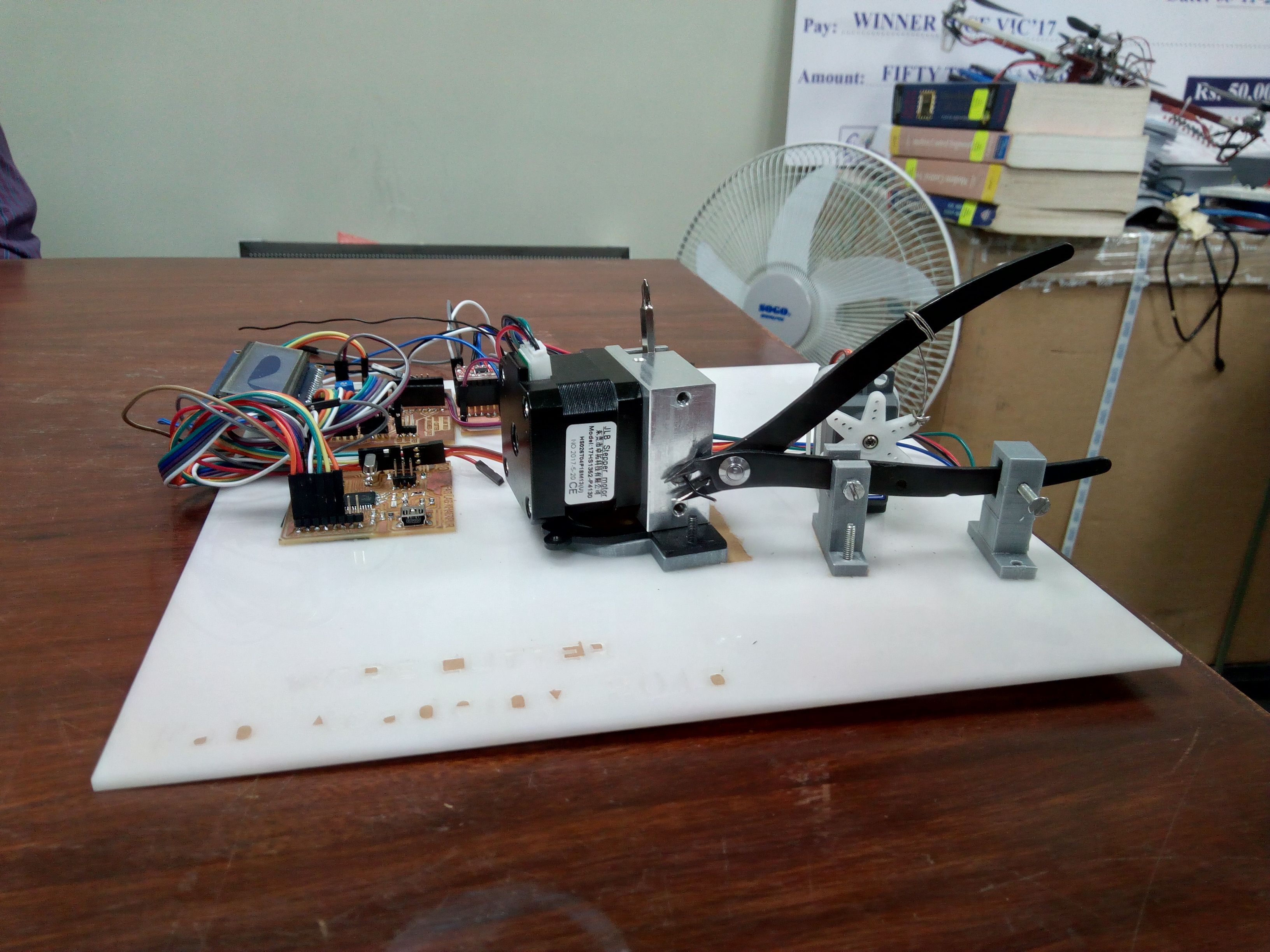
All the components were fixed on the wire cutter base, and fixed.
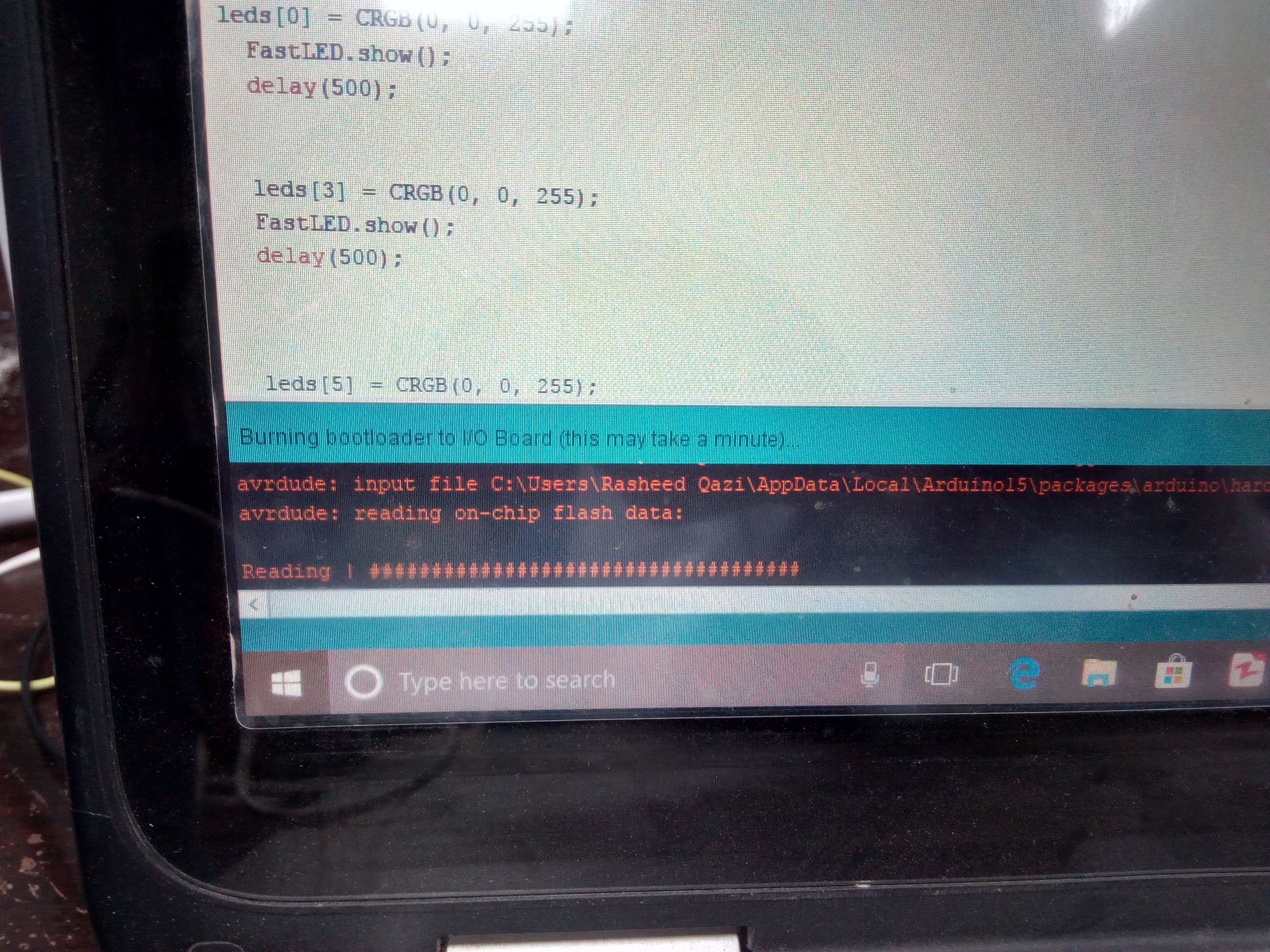
Programming in Arduino IDE
After programming the boards, I uploaded the code as shown below:
Uploading the Programming in Arduino IDE
All the components were fixed on the wire cutter base, and fixed.
In order to give a proper integration and product shape to my circuit, I had to design something to cover the electronic circuitry inside it. So, i thought to make a 3D printed case in Solidowrks. The Design is shown below:
All the components were fixed on the wire cutter base, and fixed.
.jpg)
.jpg)
The Case design in Solidworks
In order to design this case, following commands were used
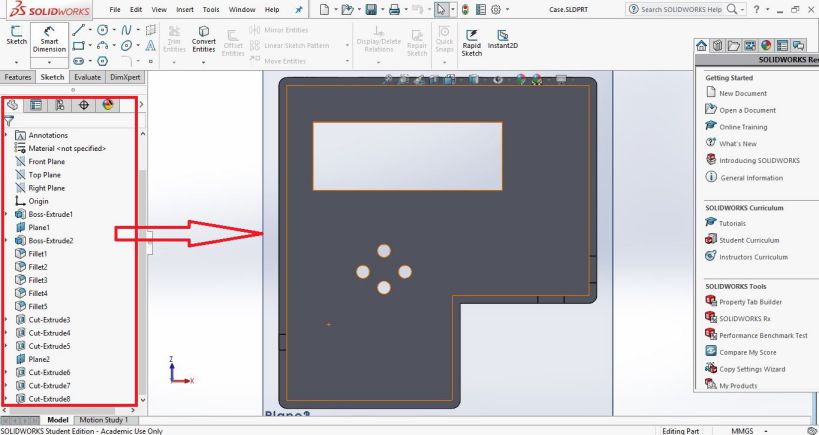
Commands used for 3D printed casing for the project
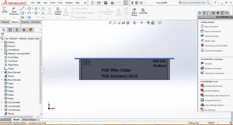
3D model of the casing from the layer perspective
Now, it was the time to save the SLDPRT as STL, and then save its gcode in Ultimaker Cura as shown below:
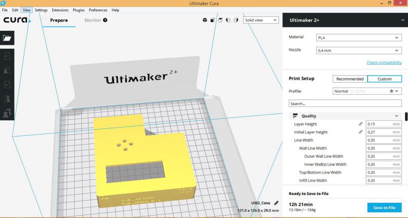
3D model of the casing in Cura for generating gcode
The 3D casing was printed and the components were fixed inside the casing as shown below:
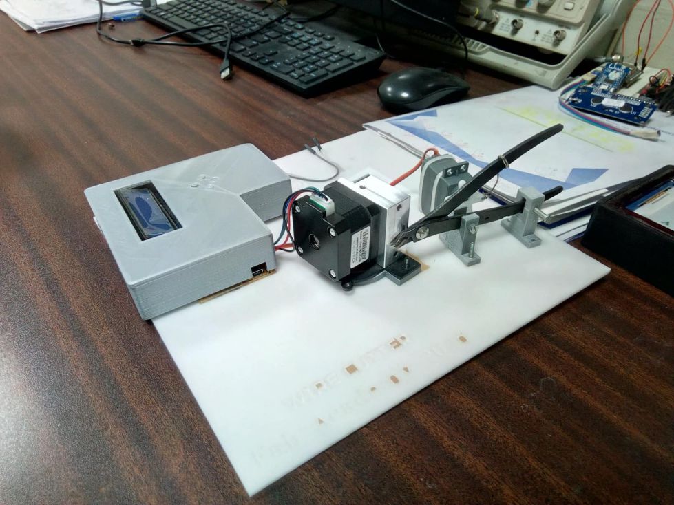
3D printed Casing for project
My final project covers following modules :
The Fab Wire Cutter was really an intresting project to do. While making this project I employed the already learned skills to make almost anything. The troubleshooting of different parts of circuit gave me a better insight about each component like Stepper motor driver IC, SErvo motor etc. The project will be used in our lab , and further improvement from the perspective of design and accuracy will be made.
