WEEK-6
3-D Scanning and Printing
Lecture & Recitaton of a Week:
Lecture on 21st of February, 2018: 3D scanning and printing by Neil Gershenfeld
Recitation on 26th of February, 2018: maker education by Sherry Lassiter, Saba Ghole and Stephanie Chang
Tasks for a Week
- group assignment: test the design rules for your 3D printer(s)
- individual assignment: design and 3D print an object (small, few cm), that could not be made subtractively 3D scan an object (and optionally print it)
Group Assignment
For group assignment, we are using .STL file which we found from Test your 3D printer! v2. The file is challenging because of its tiny size. If follows the instruction the result will come out in just 30 minutes. The file helps to check the machine calibration and it test how much precise the machine is. We have to check these parameters:
- size of the object should be 2x50x30mm (baseplate)
- Vernier can be use to check weather these hole sizes are perfect or not (3/4/5mm)
- M4 Nut should fit perfectly
- Fine detail of Pyramide, cone and numbers
- Smoothness of wave and half sphere
- minimum distance between walls and their thickness: 0.1/0.2/0.3/0.4/0.5/0.6/0.7mm
- overhang: 25°/30°/35°/40°/45°(more better the result, if more they remove easily)
- bridge print quality and its pillar distace: 2/4/8/16/mm
- surface: all the flat parts

File from thingiverse
In FabLab Khairpur we have Ultimaker 2+, Ultimaker Extended 2+ and last but not least our simplest and favourite 3D-printer Prusa i3, we use all of them to print different parts in this week.

Result from Prusa i3

Result from Ultimaker 2+
In both machines we set infill to 35 %, layer height to 0.1mm and set raft the results shows that Ultimaker 2+ extended work better than prusa i3. But here prusa i3 results dosen't show its full potential as it is not perfectily calibrated like Ultimaker 2+ Extended.
Learning Outcomes
- It is better to calibrate 3D Printer before giving job, otherwise test results may effect.
- 3D Printers have different efficiency, which can be measured by giving same file with same settings to different type of 3D Printers
Individual Assignment
3D Modeling
Working on 3-D Printer is not new for me, but 3-D Modeling is new and yet-challenging. I start to work on SolidWorks in this course and I learned of it, but still when I try to make something in it I learn more techniques to work on this software. My first individual task of the week is to design and 3D print an object (small, few cm), that could not be made subtractively. I replicate a handsfree holder from thingiverse Earbud holder by sneakypoo. It was looking easy in starting but to get it out from subtractive manufacturing it becomes complicate for me to design. I didn't get the exact copy, but I learned new techniques and solve many design challenges which I faced in this project.
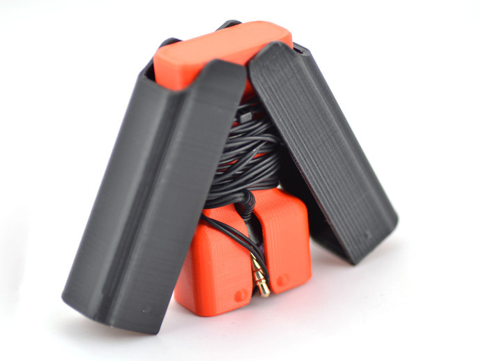
Earbud holder by sneakypoo
The holder is consist of 3 parts in which one is core body and 2 covers (Left and Right). I decided to make core and left cover and then mirror the left part to get right cover. After making parts I assembled them in Assembly file to check either my parts fit perfectily or not (I did mess 2 times in calculation, the printed results are miss calculated). I mentioned the steps with pictures below:
Designing Core (internal part):
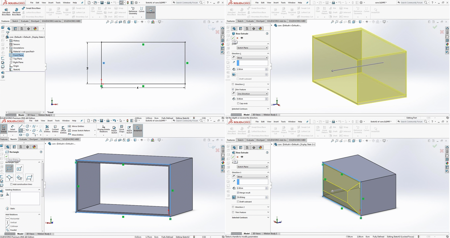
- I started with sketch to make a rectangle of 2x4cm on front plane and extruded it to 2.5cm which is enough space to hold my handsfree speaker and pin, then make a rectangle on extruded part then extrude new rectangle to 0.5cm but with draft angle of 50 degree.
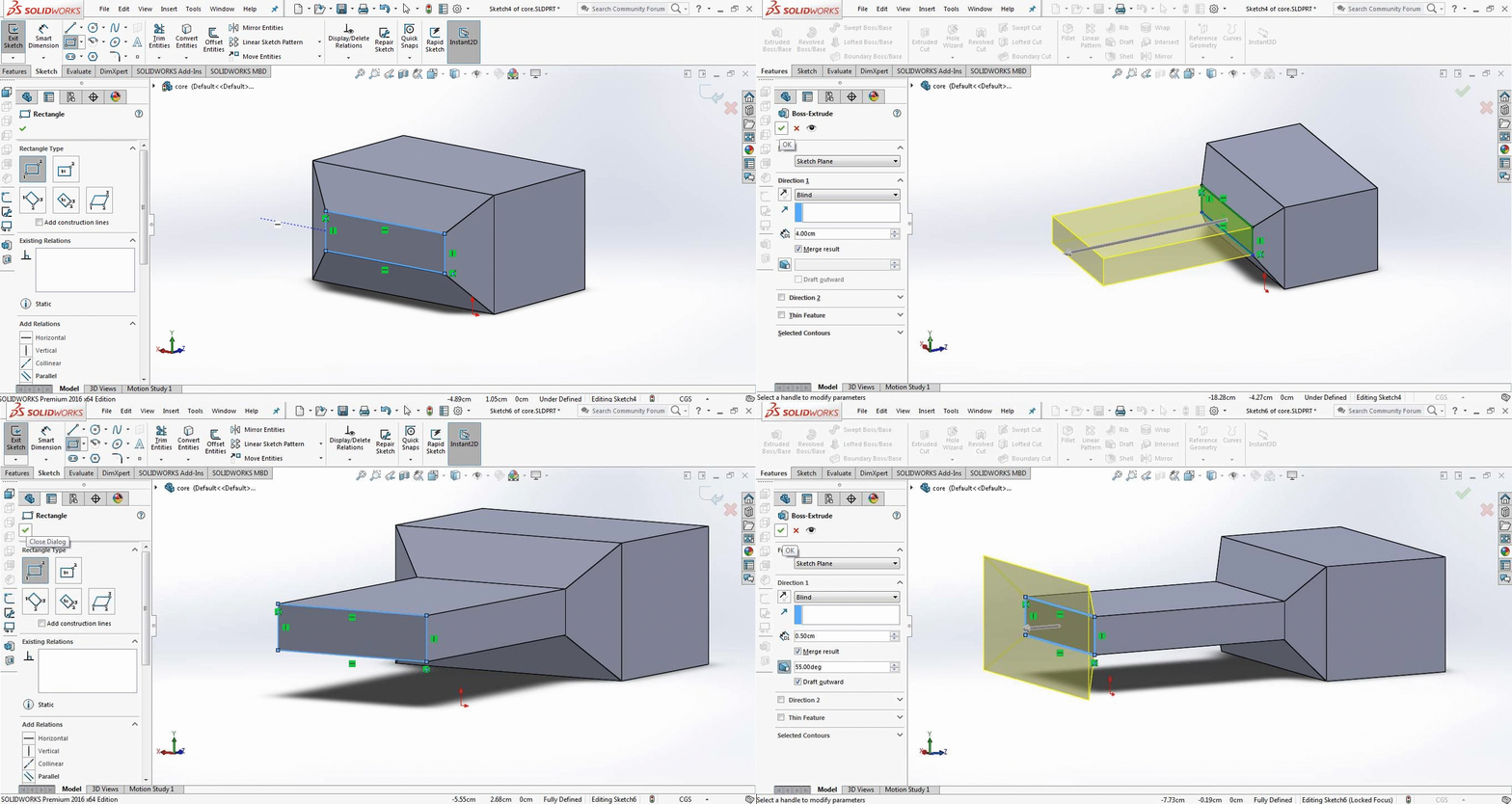
- make another rectangle on previous part and extrude it to 4cm and then make another rectangle on that and extrude it to 0.5cm with draft angle to 50 degree but this time I checked "Draft Outward"
- made last rectangle and extrude it to 1.5 cm where I wanted to attache left and right holder
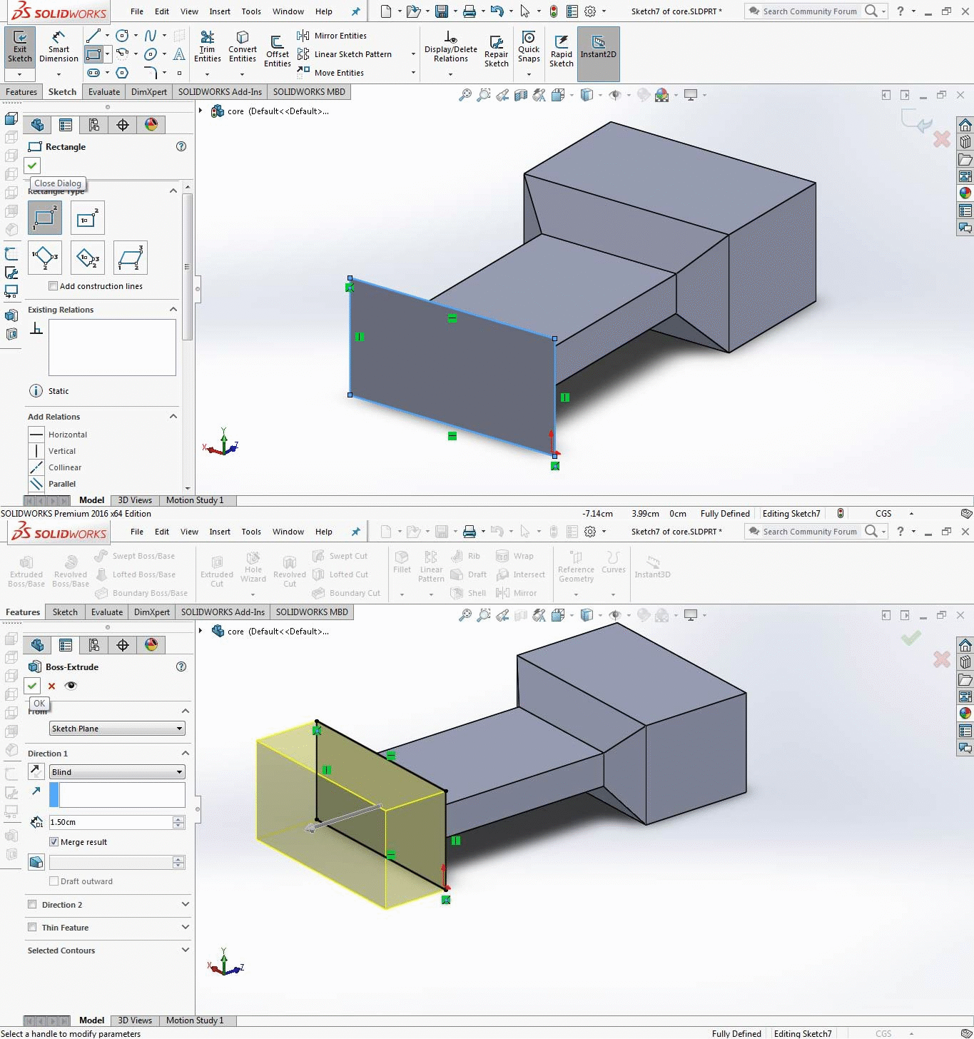
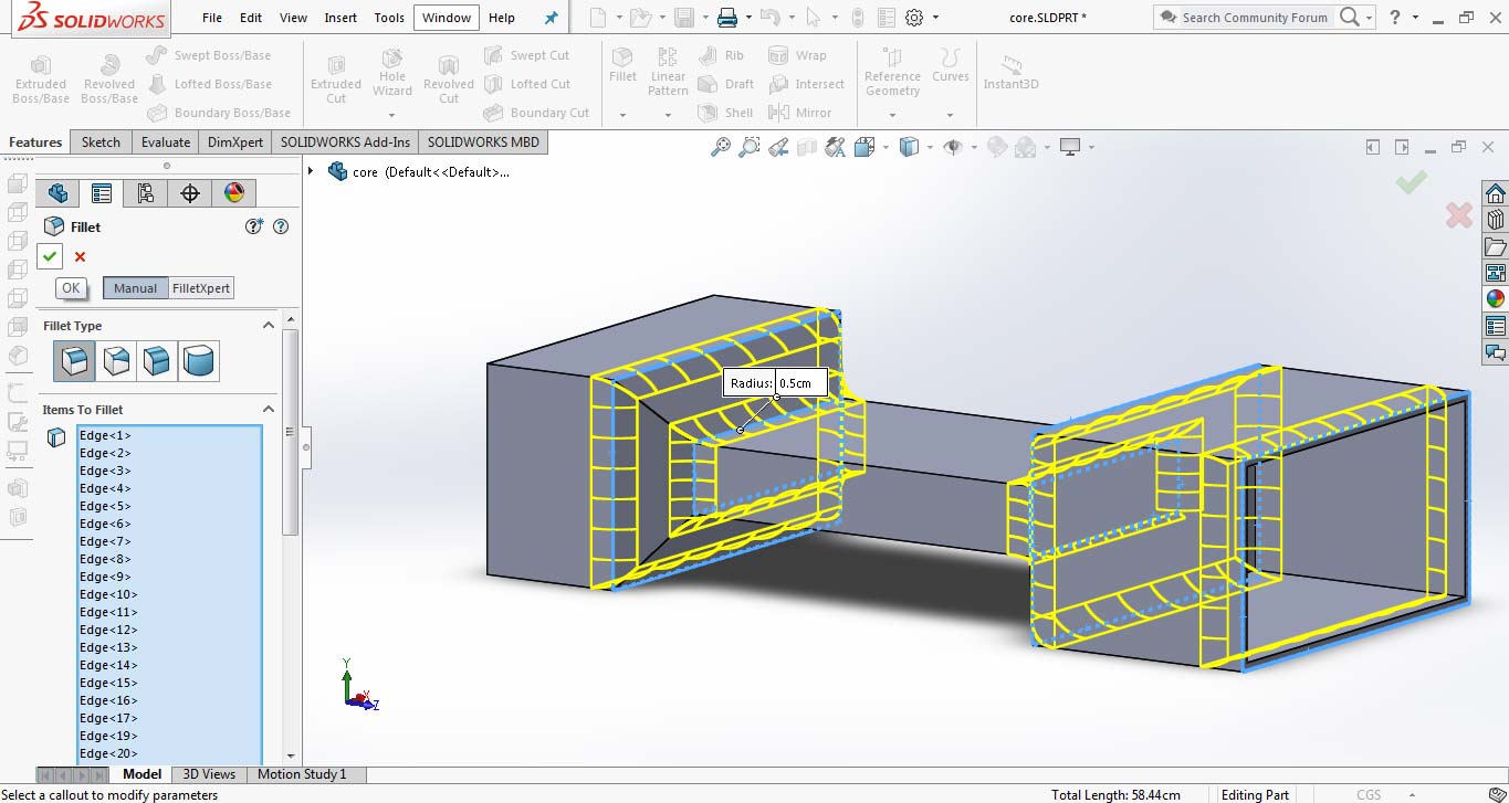
- Then I use "fillet edge" command and round these edges
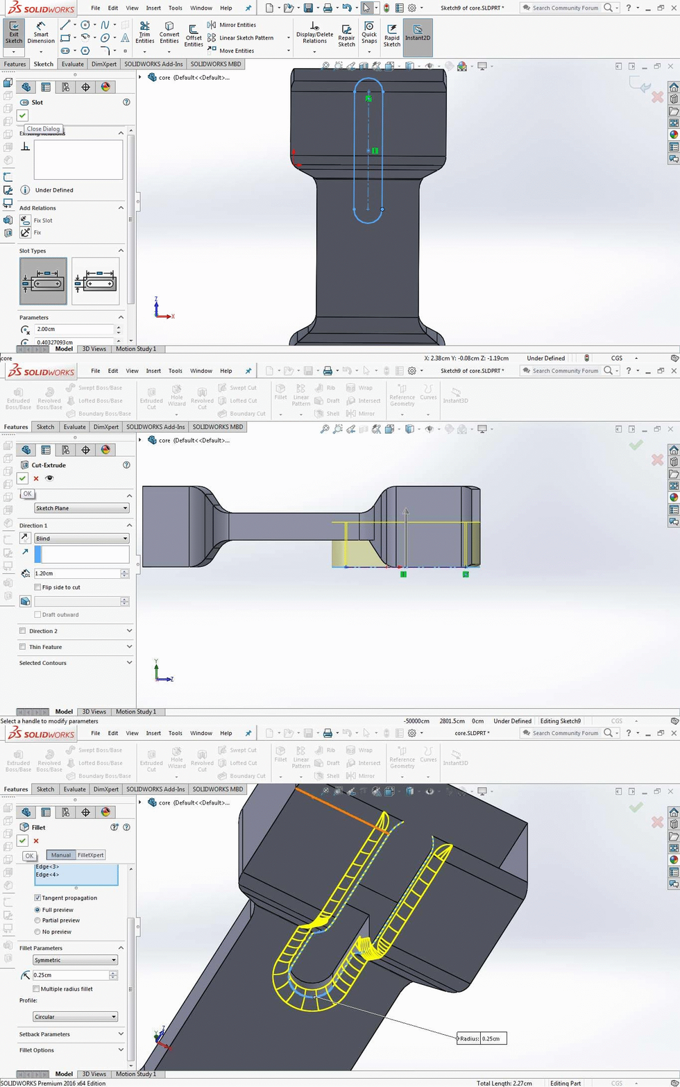
- I made a slot where my wire left the earbuds and round on the core body, slot is in shape toolbar, then cut it using extruder cut, then using "fillet edge" command to give it rounded shape
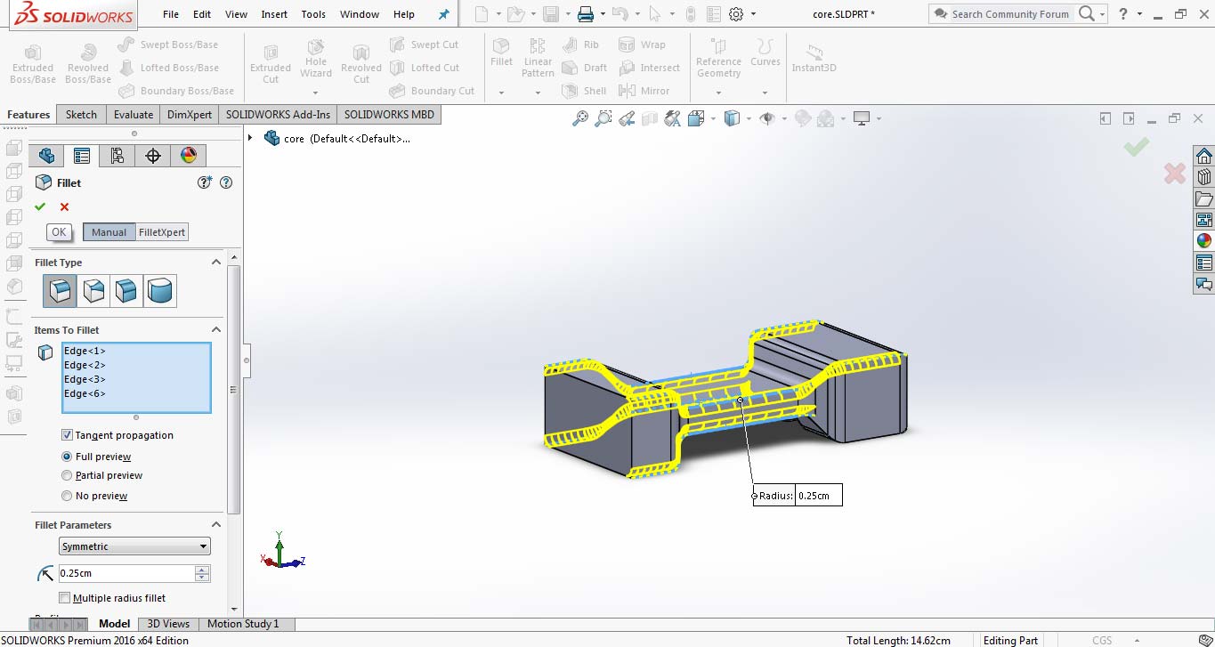
- Again using fillet to round the outer boundaries of body
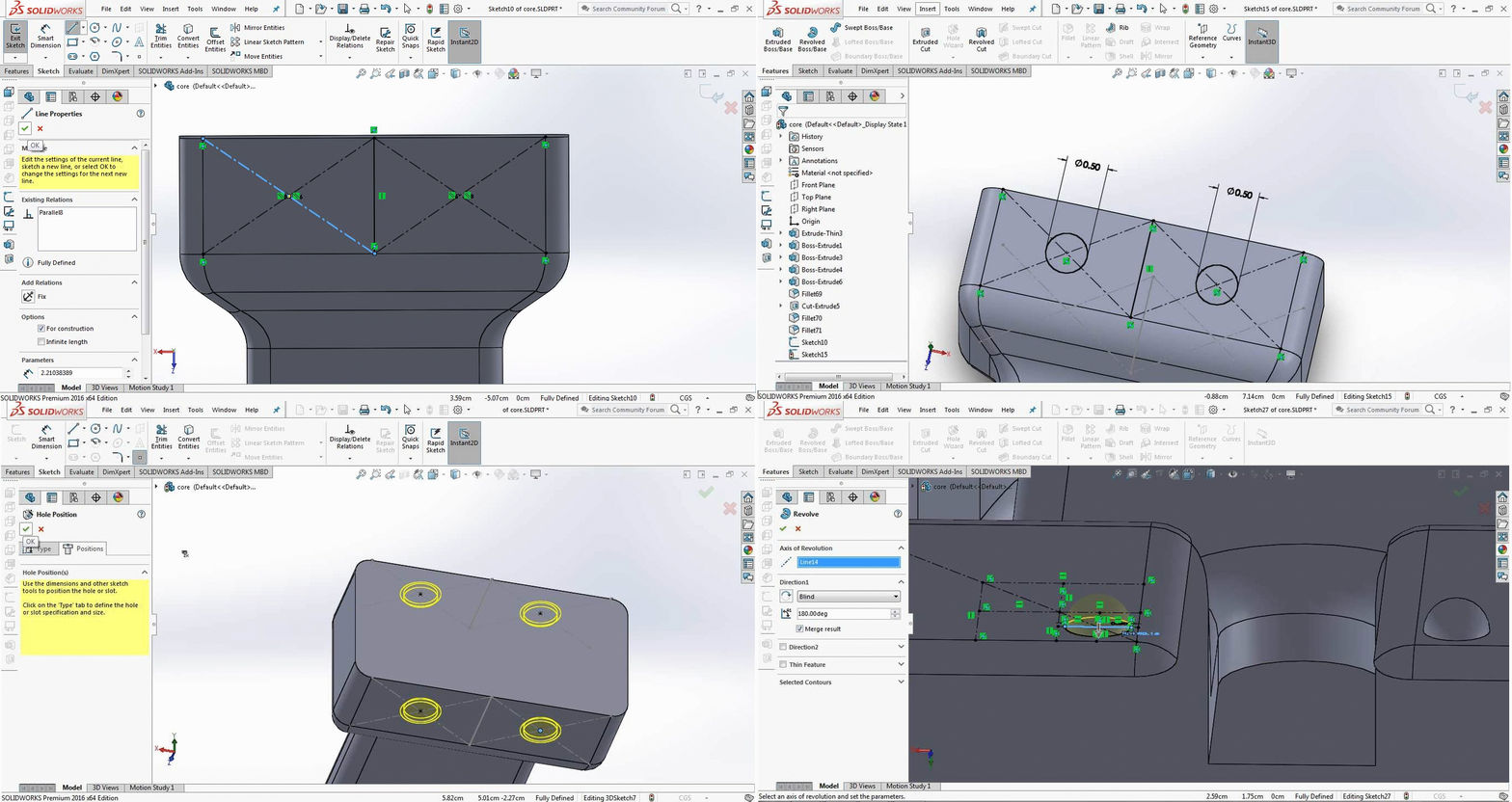
- Now I need to make some holes to fix right and left holder on core, for making holes and revolving base Fisrt I have to measure the place where I need those holes or extrude, for this I used center-line tool and make circles where I need holes, then I use hole wizard tool and select counter-sunk hole and select circles. To make revolved base First we have to make half circle then select the half circle interior part as Contour and circle axis line as line for revolve.
- The final part is out
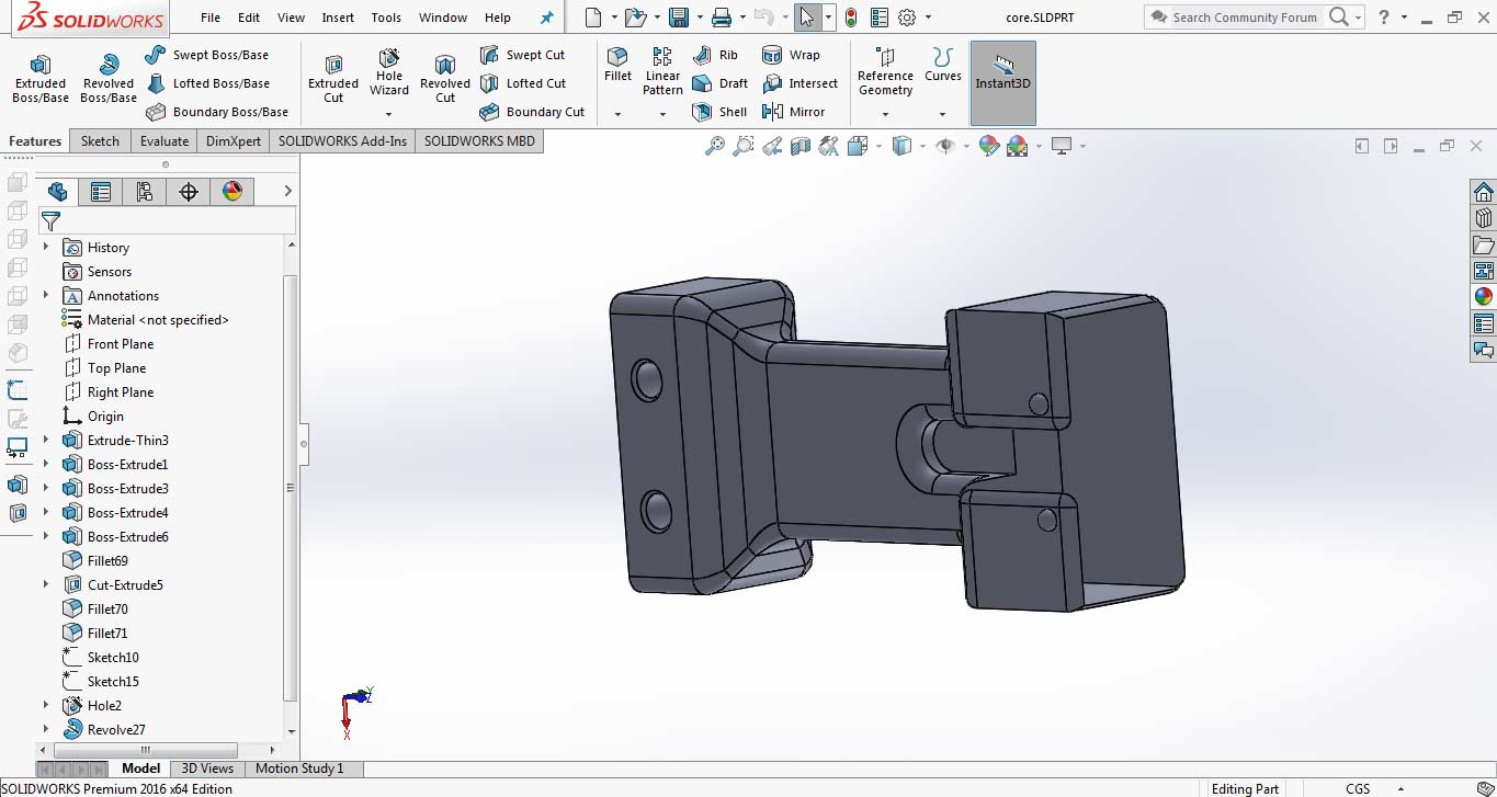
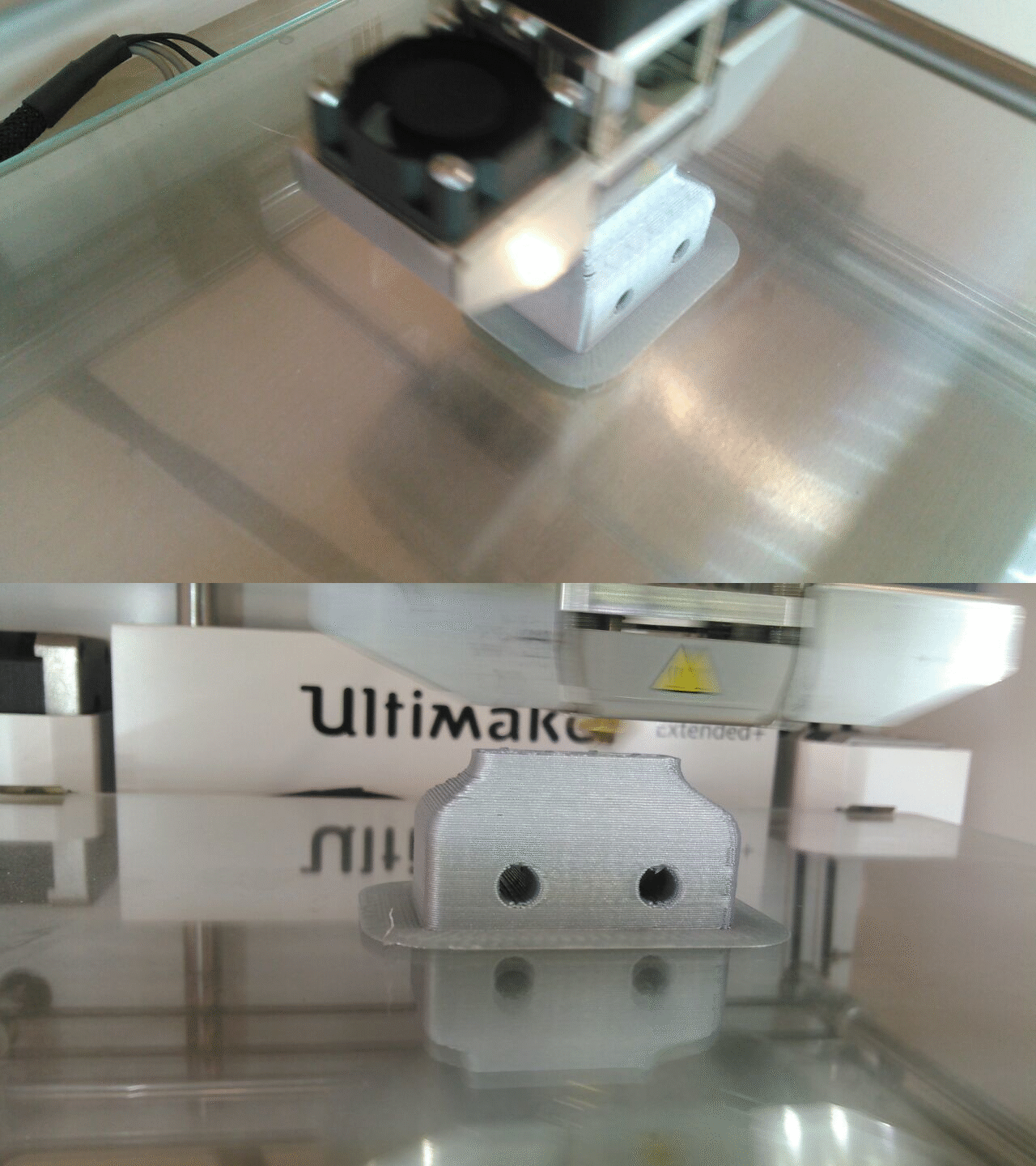
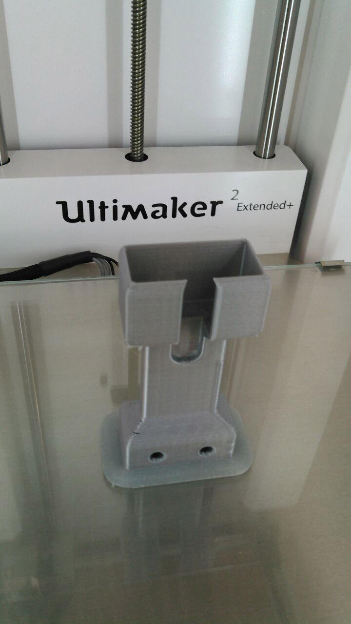
while 3D Printed
3D Printed done
Designing Cover (external parts):
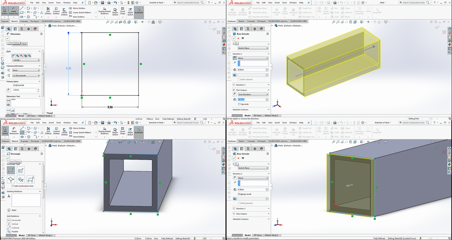
- Start with sketch to make a rectangle of 2.5x2.25cm on front plane. Extrude it to 8.8cm after calculating core part which is 8cm. Then make a rectangle on extrude part and extrude on other side to close it
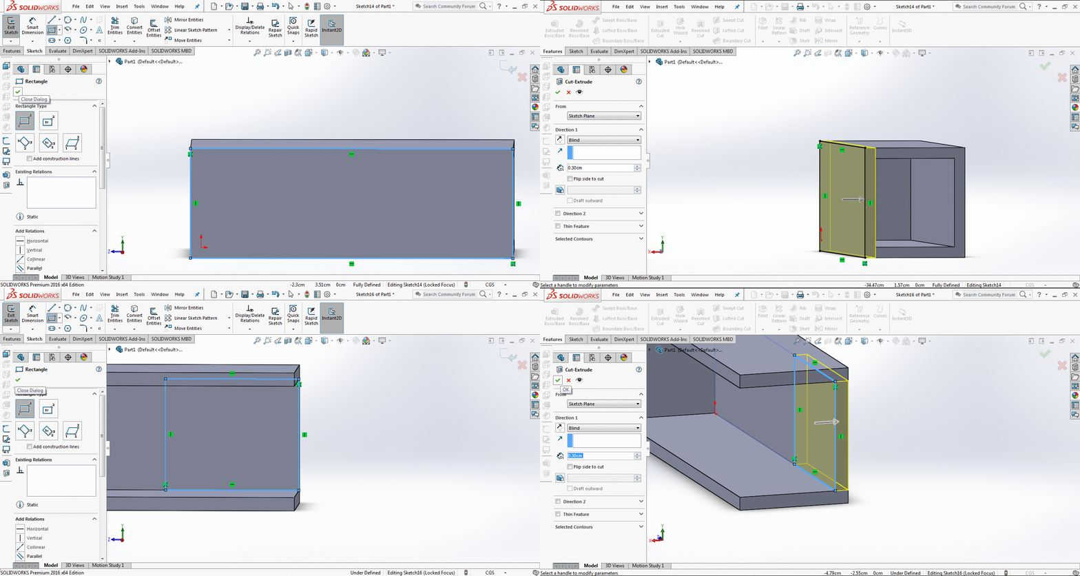
- Now make a rectangle on right side of box and extrude cut it to open the box from one side. Then on the side behind that side internally I make a box and extrude cut it to make a space to open and close the holder easily on core
- To fix the holder with core I needed to extrude some circles, for this I measure the corner part using center-line and make a 0.6 dia cirlce, extrude that cicle to 0.04cm with draft angle to 50 degree. The I made half circle on it, select internal region of half circle as contour and axis line to rotate towards it.
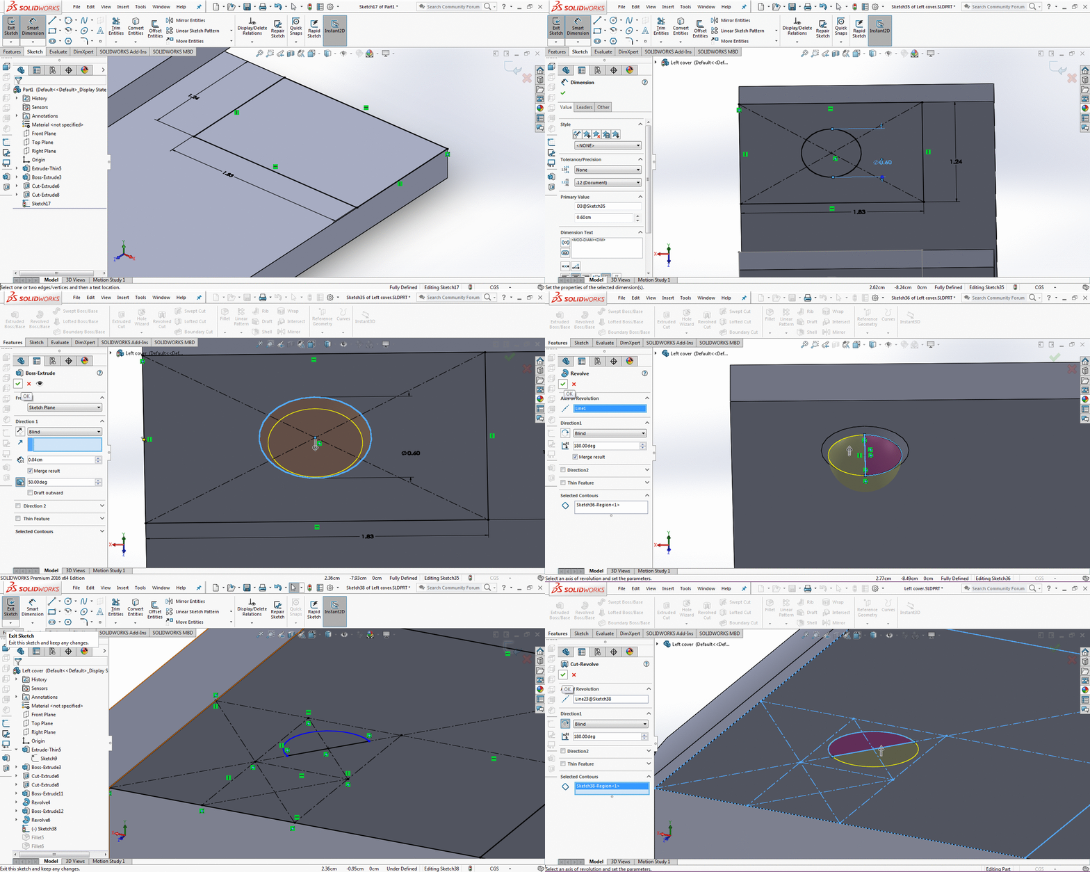
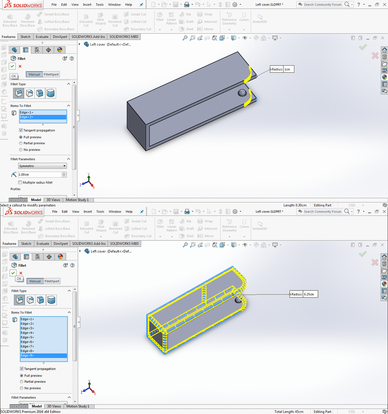
- Then I fillet the edges with different sizes to smooth the surface
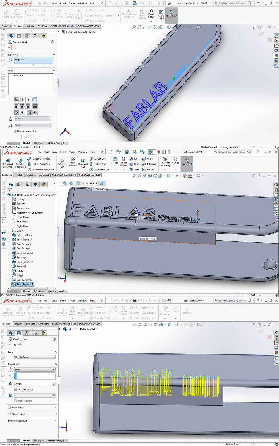
- Then I wrote my FABLAB name on it using Sketch Text Tool and drag it towards downward to 0.2 cm to look it like engraving
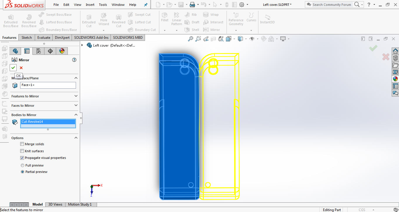
- Then when part makes I a copy of it by mirroring, it has 2 option select the face where to mirror, select the body to mirror and uncheck on "Merge Solids" to make software conside them two different bodies
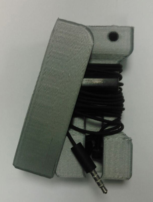
- The result is not achieved as I calculated. I printed left cover but it does not fit, it is small as compared to core body
- I increased the length to 8.8 cm to 9.5 cm it the size is become too big now
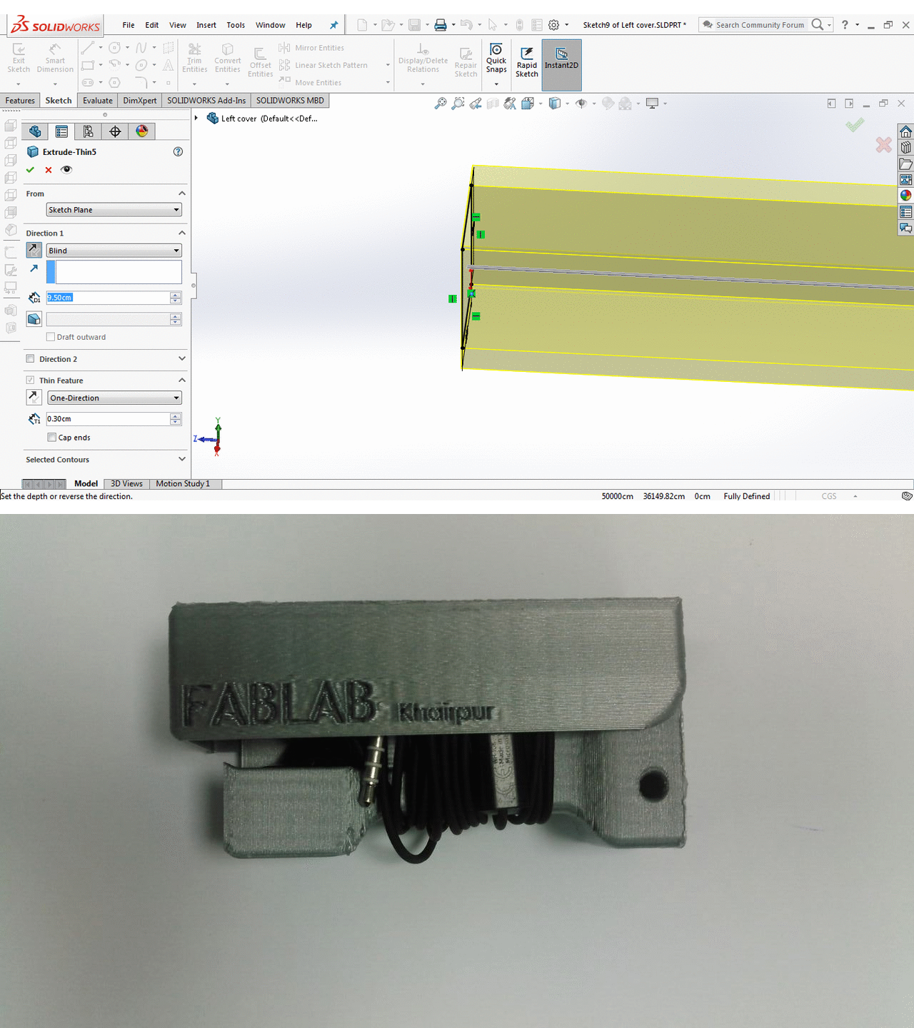
- I decreases the size to 9.10, then I again print it using Prusa i3 the result is very near but still no use it is tight to touch boundary
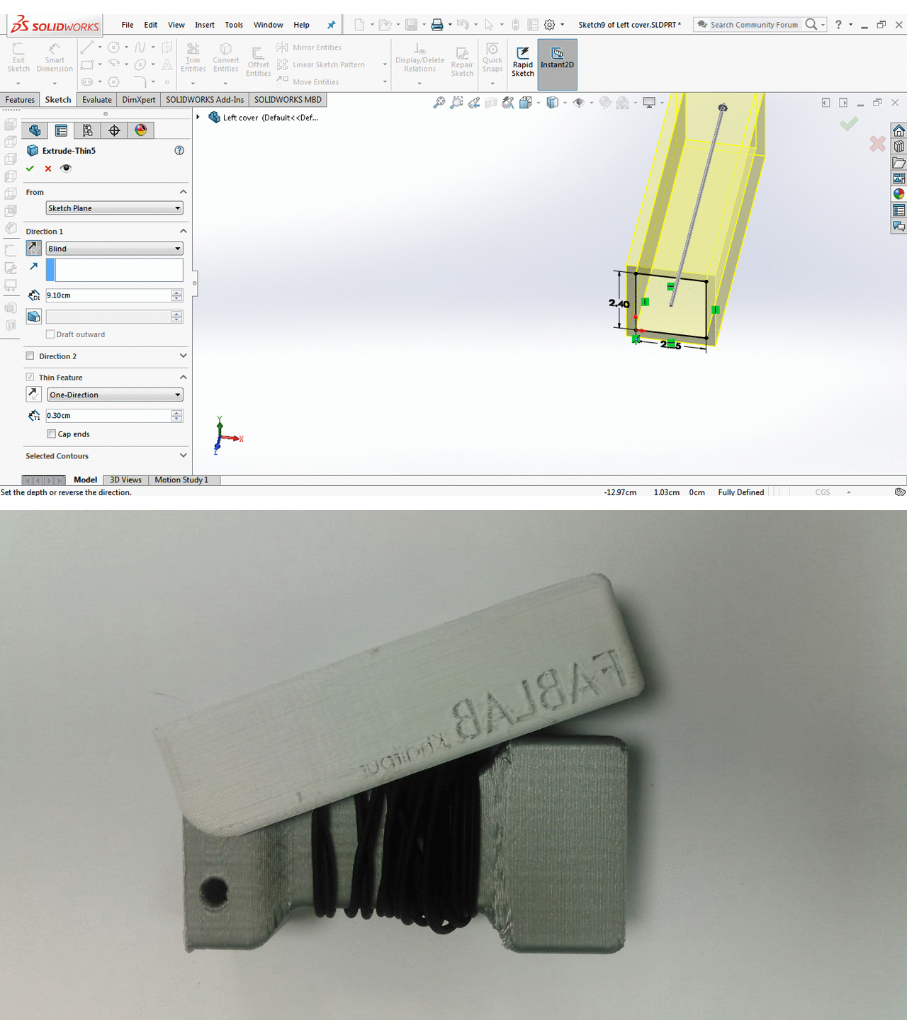
- One more try this tipe I increase size to 9.25 and width to 2.45cm and the expected results are achieved
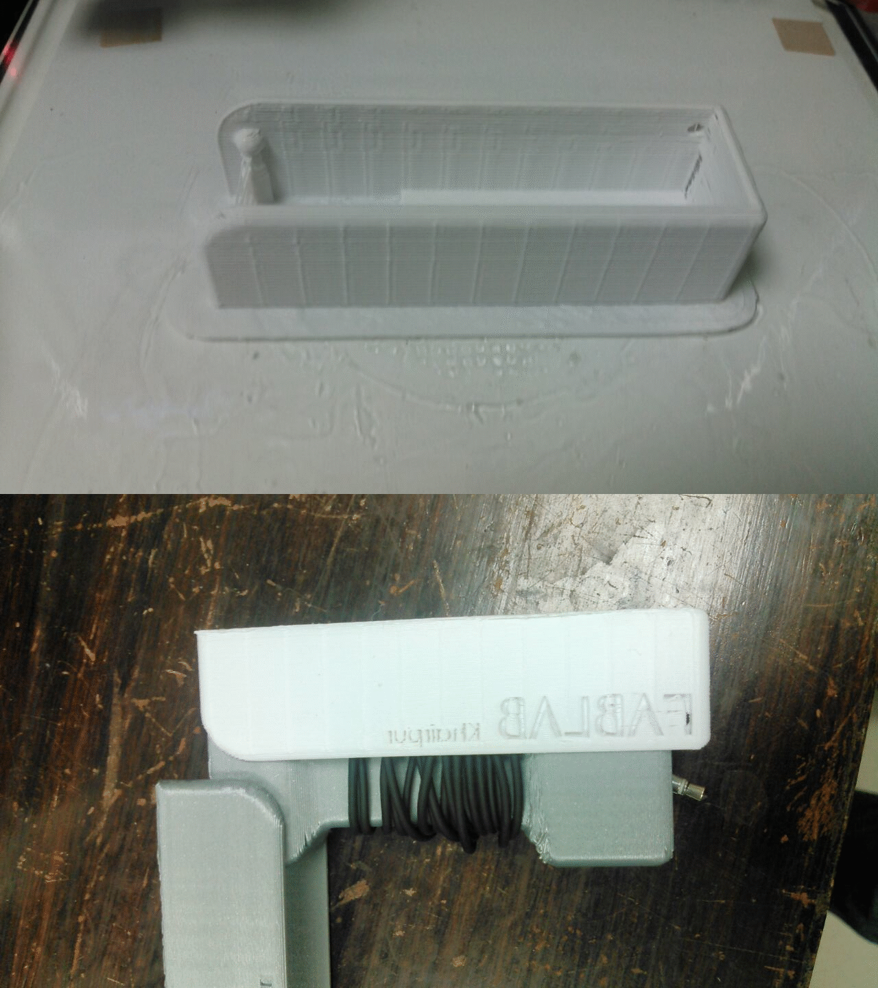
Designing Additive Model:
It is difficult to made above project in subtractive manufacturing but it is possible. So I decided to make 1 more project for this week. I made some 2 3D hollow shapes Cube and Paramid and connect them in chain form, which cannot be made subtractively, because if we make them in subtractive wy how we suppose to join them within each other
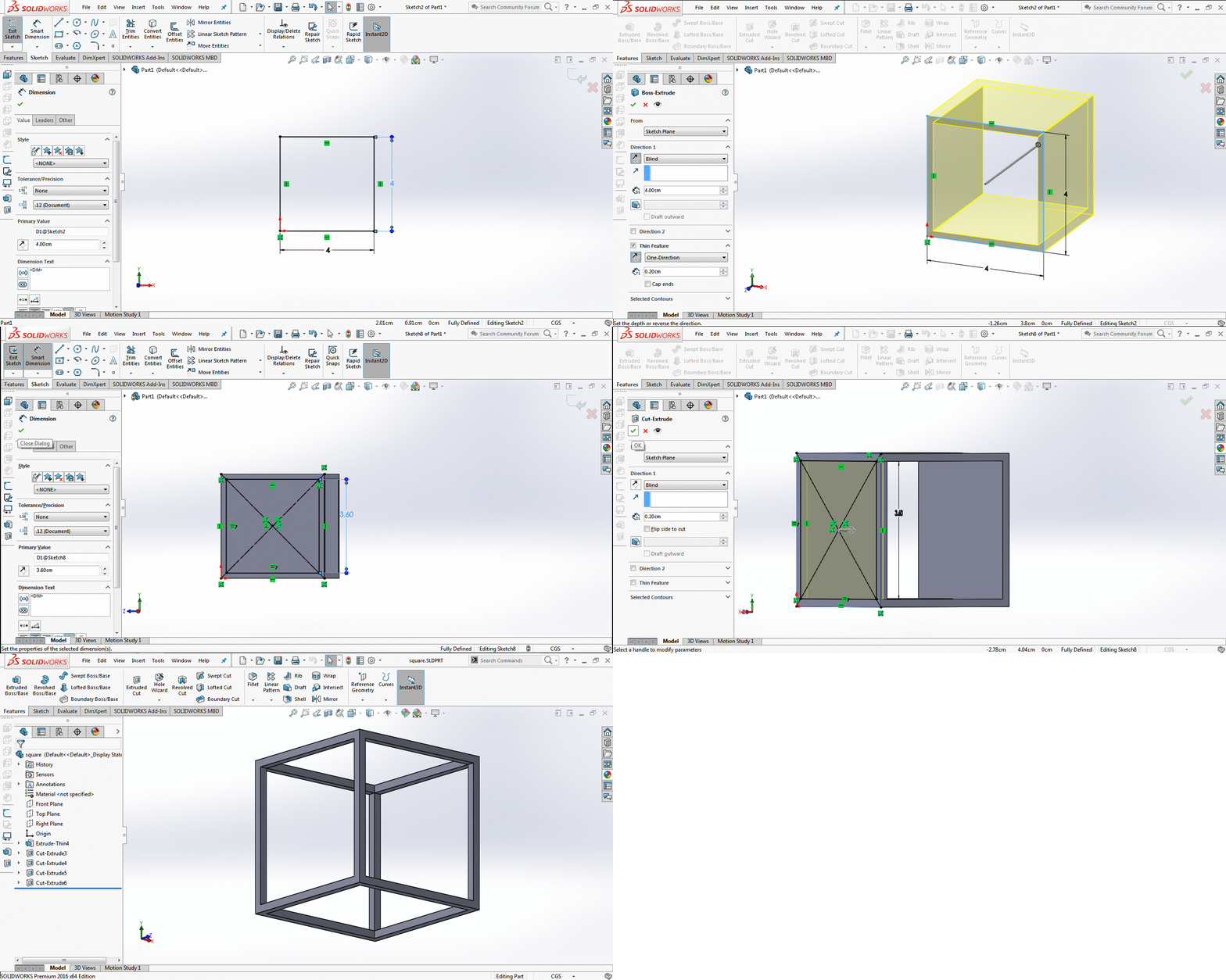
- For making cube first I made 4x4cm square in sketch then I extrude it to 4cm by selecting thin feature to 0.20cm. the shape was open from two side so I open sketch in another side and make square on it of 3.6x3.6cm and then extrude cut it. So make it hollow. Repeat this on other remaining 3 sides and my hollow cube is ready
3-D Modeling of hollow Cube
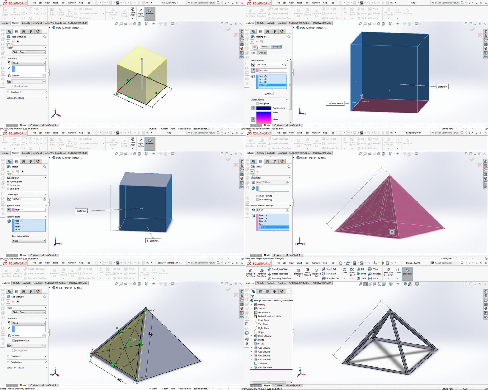
- For making pyramid first I made 4x4cm square in sketch then I extrude it to 4cm. The I use draft tool and select the bottom part as direction of pull and select other perpendicular sides of cube as draft face. I select 30 degree angle and draft towards inward to make cube as paramid. After making solid pyramid I need to hollow it from inside so I used "Multi thickness settings" of "shell" tool and select all 5 faces to hollow the pyramid from inside. I make rectangle on each pyramid side of 3.6 and cut extrude it to 0.2cm and the end result is shown in gif
3-D Modeling of hollow pyramid
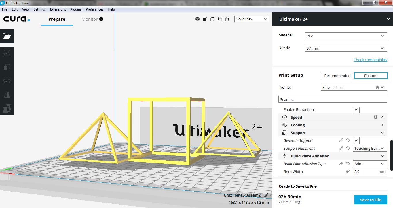
- After making both parts we open them in assembly (as mentioned in above model) and set them for 3D Printing.
Cura software display for setting up job for Ultimaker 2+ Printer
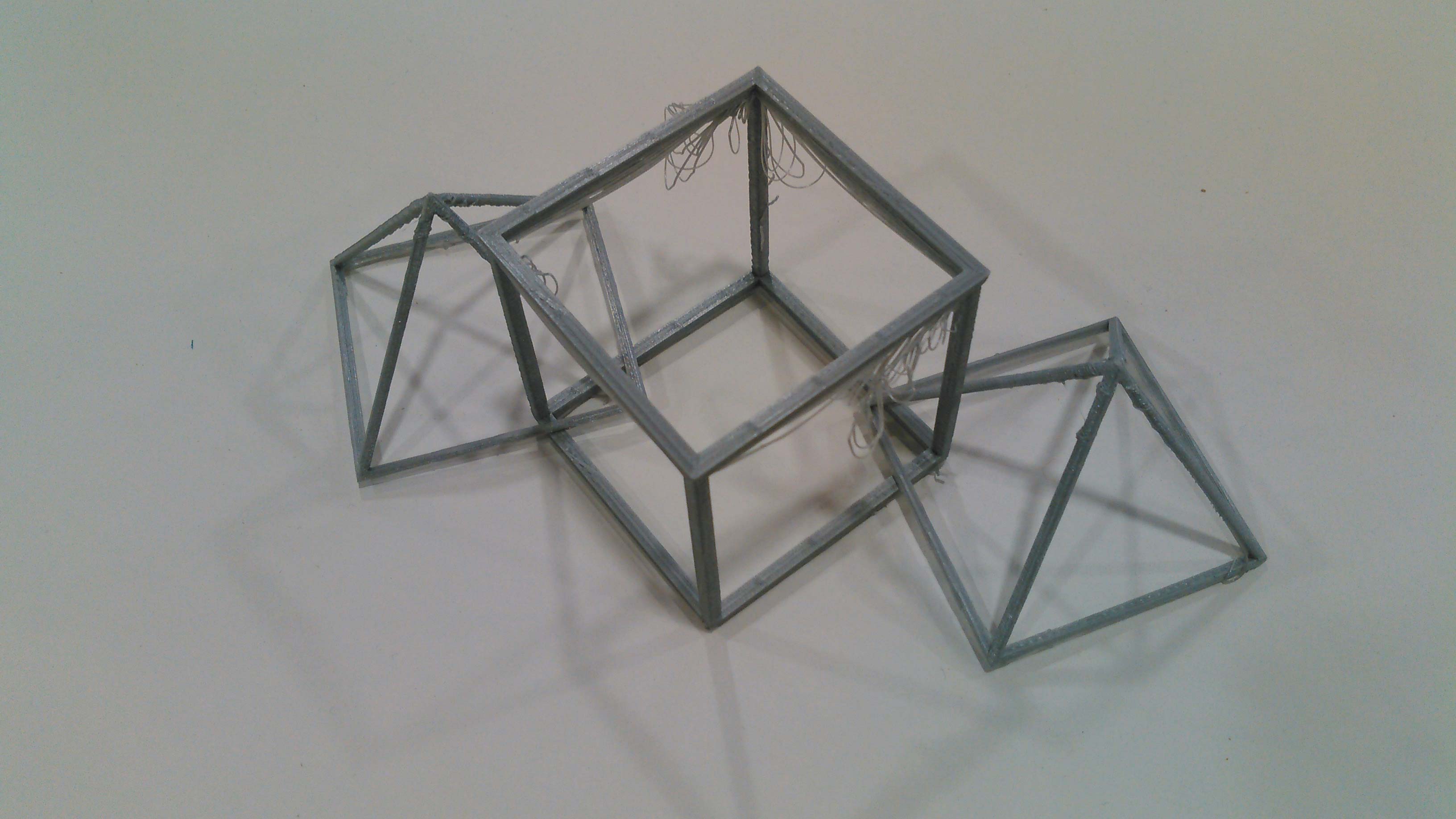
- I forgot to give support in Job while setting up the model in Cura software but still it manages to complete the task. All 3 shapes are locked together with each other in chained structure which can not be made subtractively.
Cube Pyramid 3D printed chain
3D Scanning
I never n.use Kinect before like this, its a completely new and interesting experice to scan ourself. For this we download "KinectDeveloperToolkit-v1.7.0-Setup", "KinectSDK-v1.7-Setup" and "Skanect-1.9.0-win64" after downloading them we start Kinect and we follow these steps:
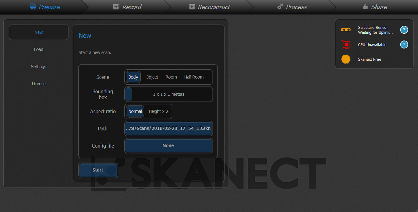
- Plug in Kinect adapter in supply and plug usb cable in PC. Open Skanect, select "New" then click "start"
Skanect first screen
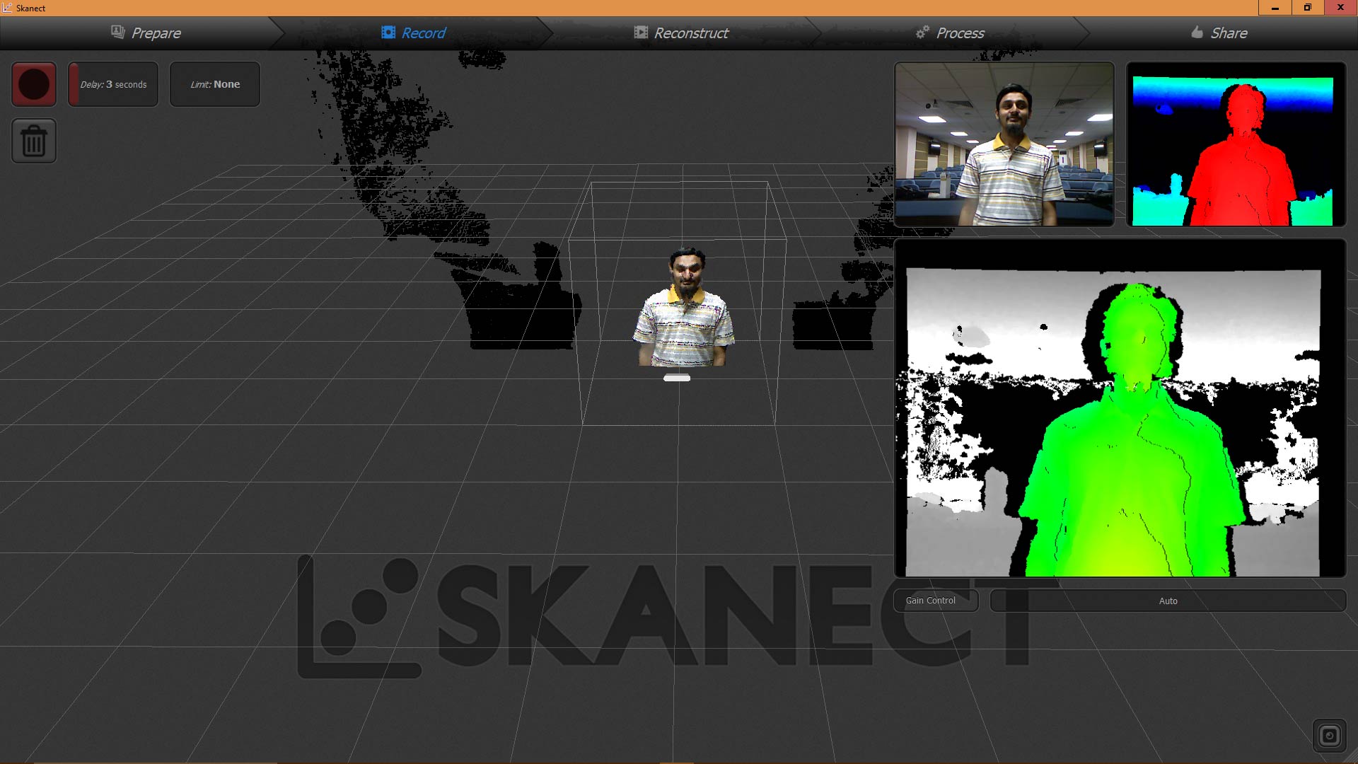
- Select Delay time and click on Record (red button)
Record tab
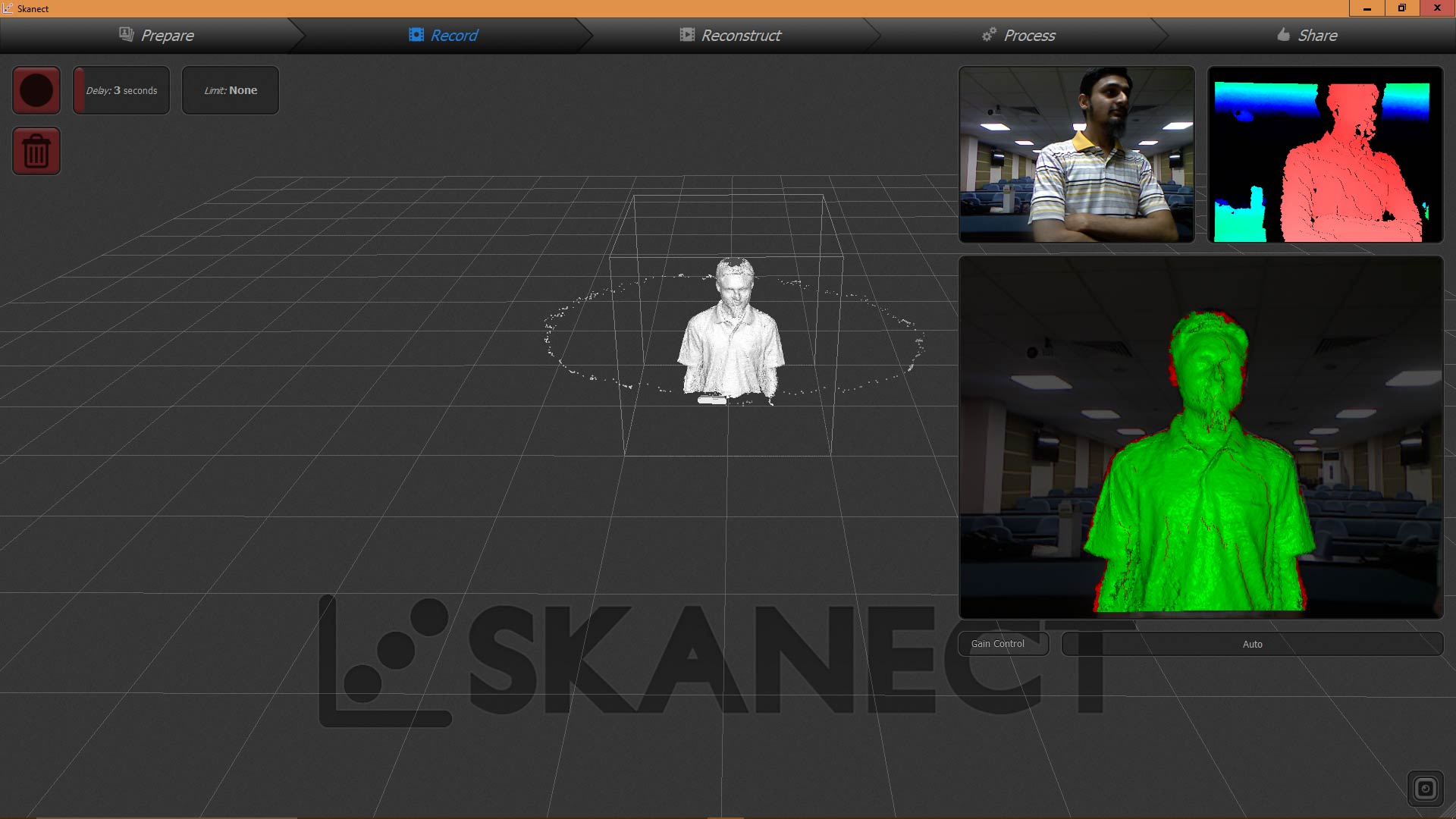
- Move slowly and precisely to record video, stop and wait if red color comes on screen
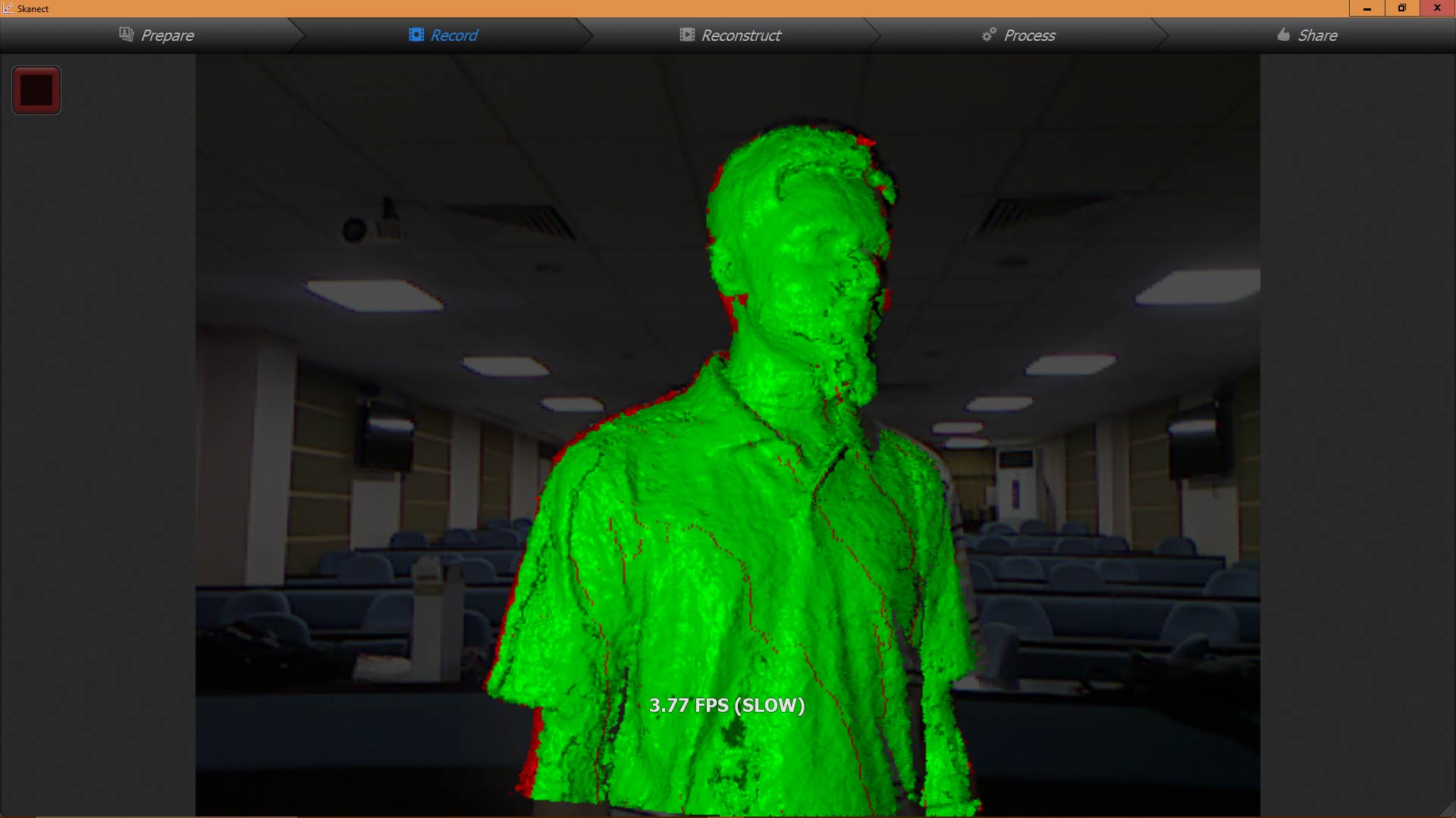
- Press red button when circular scanning is complete, After processing the reslt will be shown:
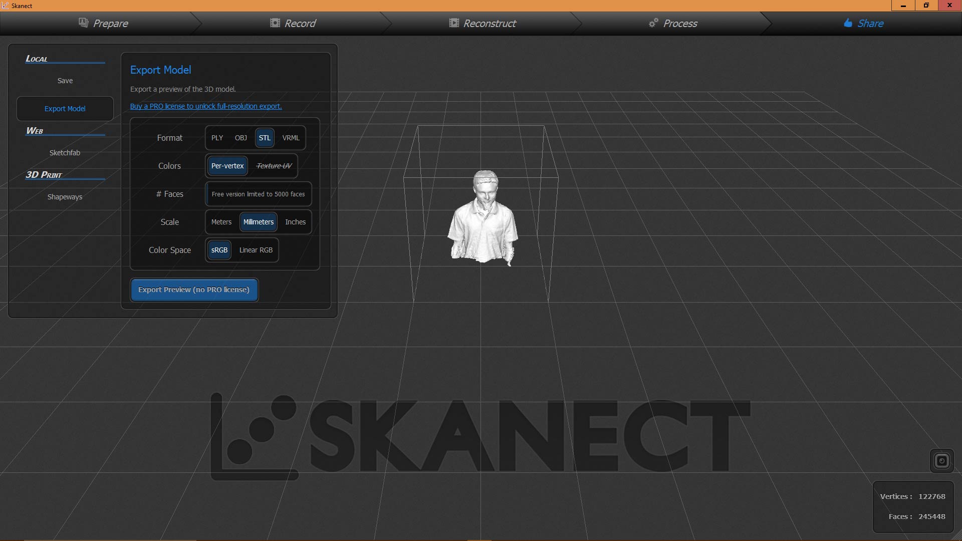
- In Share tab select .STL as format and scale as millimeter and click on export preview and save it
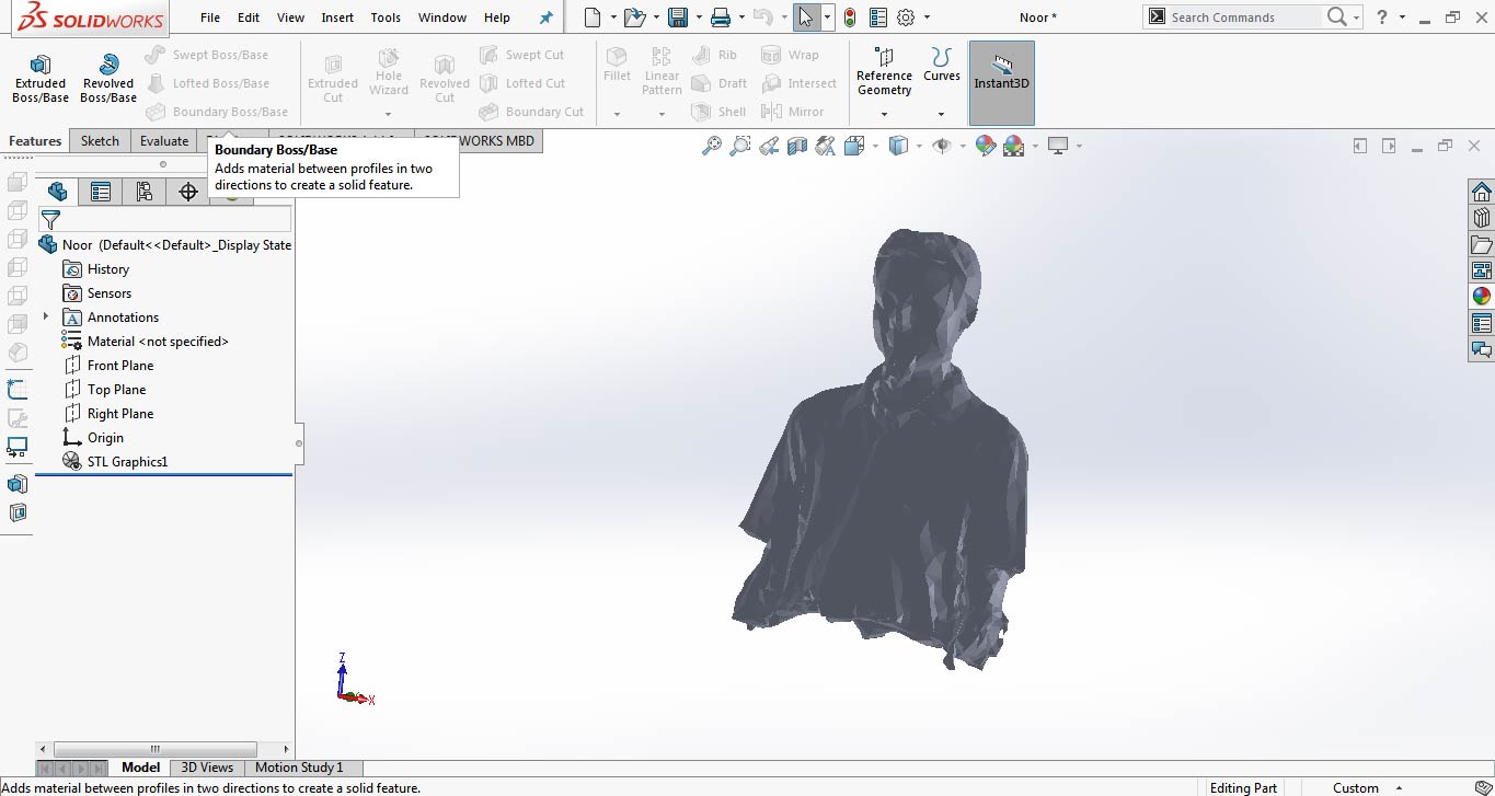
- The preview of .STL file in SolidWorks
"Click here"to download all files of this week

This work is licensed under a Creative Commons Attribution-NonCommercial 4.0 International License

