


Electronics Production
This week was very interesting for me because I like to fabricate SMD based circuit and solder them. Although it was bit challenging for me to solder such small components, by the I managed it. In this week our task was to produce our own "FAB ISP in circuit programmer". And, code uploaded successfully on my fabricated ISP in the very first attempt.
- Group Assignment
- Characterize the specifications of your PCB production process
- Individual Assignment
- Make an in-circuit programmer by milling the PCB
- Then, optionally trying other processes
Assigned tasks of the week:
Learing outomes
- Process of milling, soldering, debugging, and programming
For group assignment, we have to characterize the specifications of PCB production process and for that we are using Roland monoFAB SRM-20 Milling machine. For learning process in both group and individual assignments we are using basic PCB Board which is FR-1. We are fabricating a Traces-width board, which has a traces which is very near in different sizes. For cutting and traces we are using 1/32 and 1/64 drill bit respectively.
Fabricating PCB
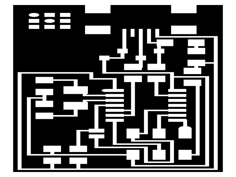
We used these png files for trace and outline


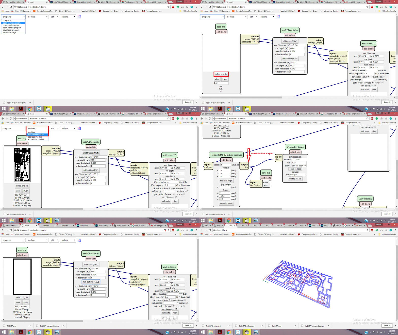
Steps for generating .rml files:
- In the program tab, click on open server program.
- Click on PCB under SRM-2.
- Click on image(.png) as your input format file.
- Browse and open your desired png file.
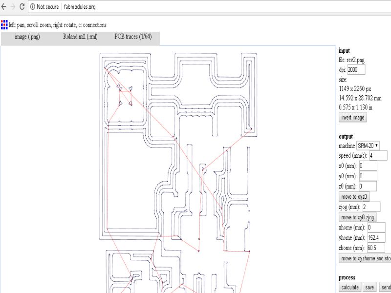
- After opening your file, select mill traces 1/64.
- Go to the modules tab and click on add server module.
- Click on save.
- A pop-up will appear as shown below, drag this file and connect it to the output node of Rolland SRM-20 milling machine.
- Click on "Calculate" and the file will be saved automatically.
- rml file is read.
- To check the traces and path of PCB , click on view.
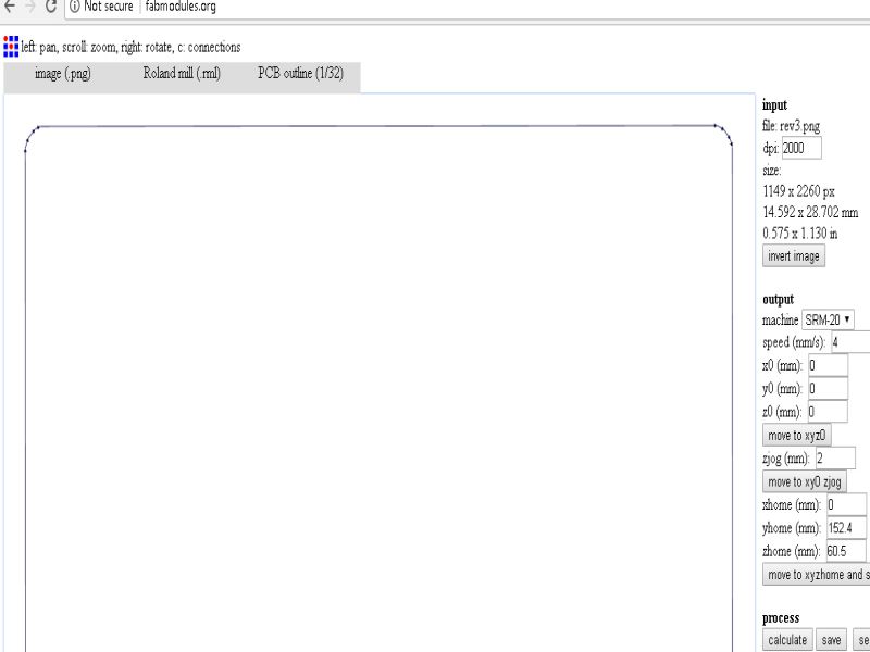
- Select the png format of outline and click on mill traces 1/32 and click calculate to save this file.
Following gif file shows the process of generating rml files
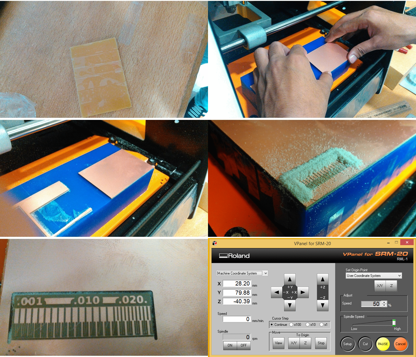
After generating RML files, we send both files to ROLAND monoFAB SM-20 Machine. following steps describes the working of machine.
- Place copper clading board on wax block (or use wooden block instead of wax block).
- Open VPanel for SRM-20 in PC.
- Change the drill bit, fixed 1/64 bit for tracing.
- Select origin to x/y and z axis by changing values of x, y and z axis to set the origin.
- Click on "Cut" and select desired .rml file which we want to use.
- Click on "Output" to start the process.
Following gif file shows the process and working of the machine.
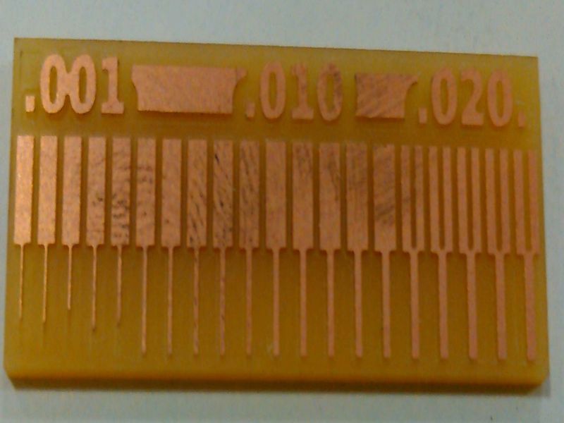
The group assignment shows that how much precisely machine works with 1/64 drill bit.
Being an electronics engineer, this tasks was not challenging for me. I have basic knowledge about soldering of through-hole components. But, soldering of SMD based components was very new for me. I liked to work with Roland SRM 20 which is available in our lab.
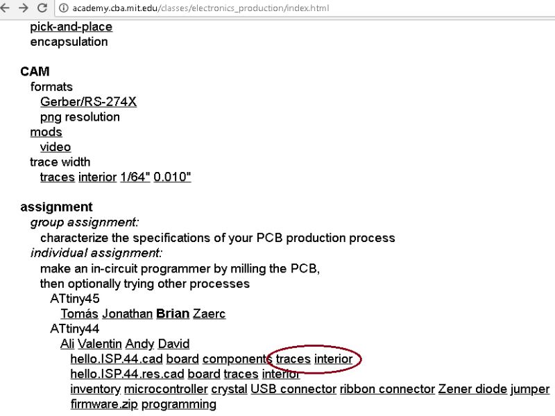
The task for this week is to make an in-circuit programmer by milling the PCB. So, for that I download development board file from this week's lecture.
Following images shows my downloaded files

I generated .rml files through FabModules. Following images are shown.


Soldering the board
Now I am in my favourite job that is soldering the board. Easily I soldered all the required components onto the board.

Debugging process
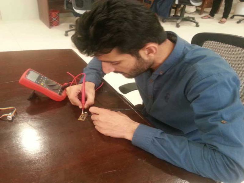
Circuit board is soldered, now the main step comes, that is checking the connectivity of the paths and checking proper flow of source in the circuit on each component. So, for that I used digital multimeter, I checked connectivity of ground, VCC and other pins of microcontroller. When this step completed successfully, I jumped to the next step that is up the circuit.

We dedicated one computer of our lab to Linux, and installed Ubuntu in that computer. I never used Linux based OS before, so it took much time to programme the board.

Few glimps of Linux results while programming my board


The last thing is to remove zero ohm resistor from the board, for using it to burn bootloader other microcontroller boards.
Download all files from here
This work is licensed under a Creative Commons Attribution-NonCommercial 4.0 International License.


