Week 05: Electronics Production
For my individual assignment I started off with a board template by Andy Bardagjy provided on the FabAcademy website. This template is documented as schematic (Fig.01) and assembly drawing (Fig.02), plus the board design (Fig.03) and contour desing (Fig.04) for export to milling.
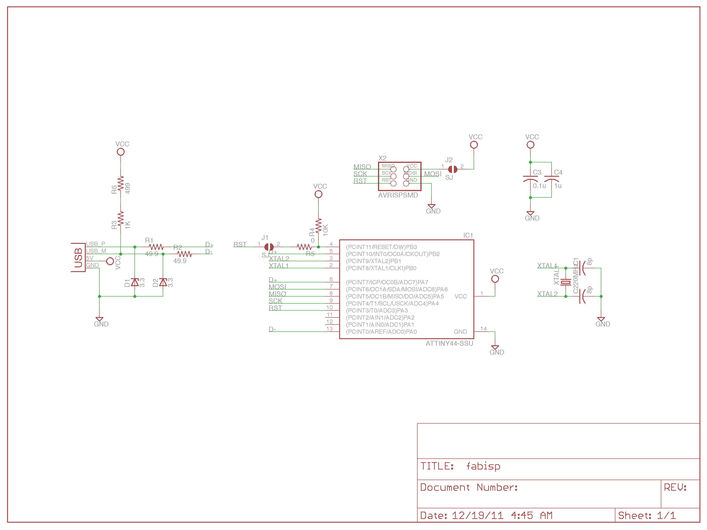 Fig.01: Schematic drawing. |
 Fig.02: Assembly drawing. |
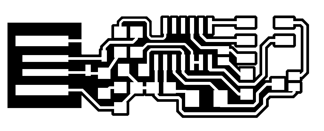 Fig.03: Board design. |
 Fig.04: Contour design. |
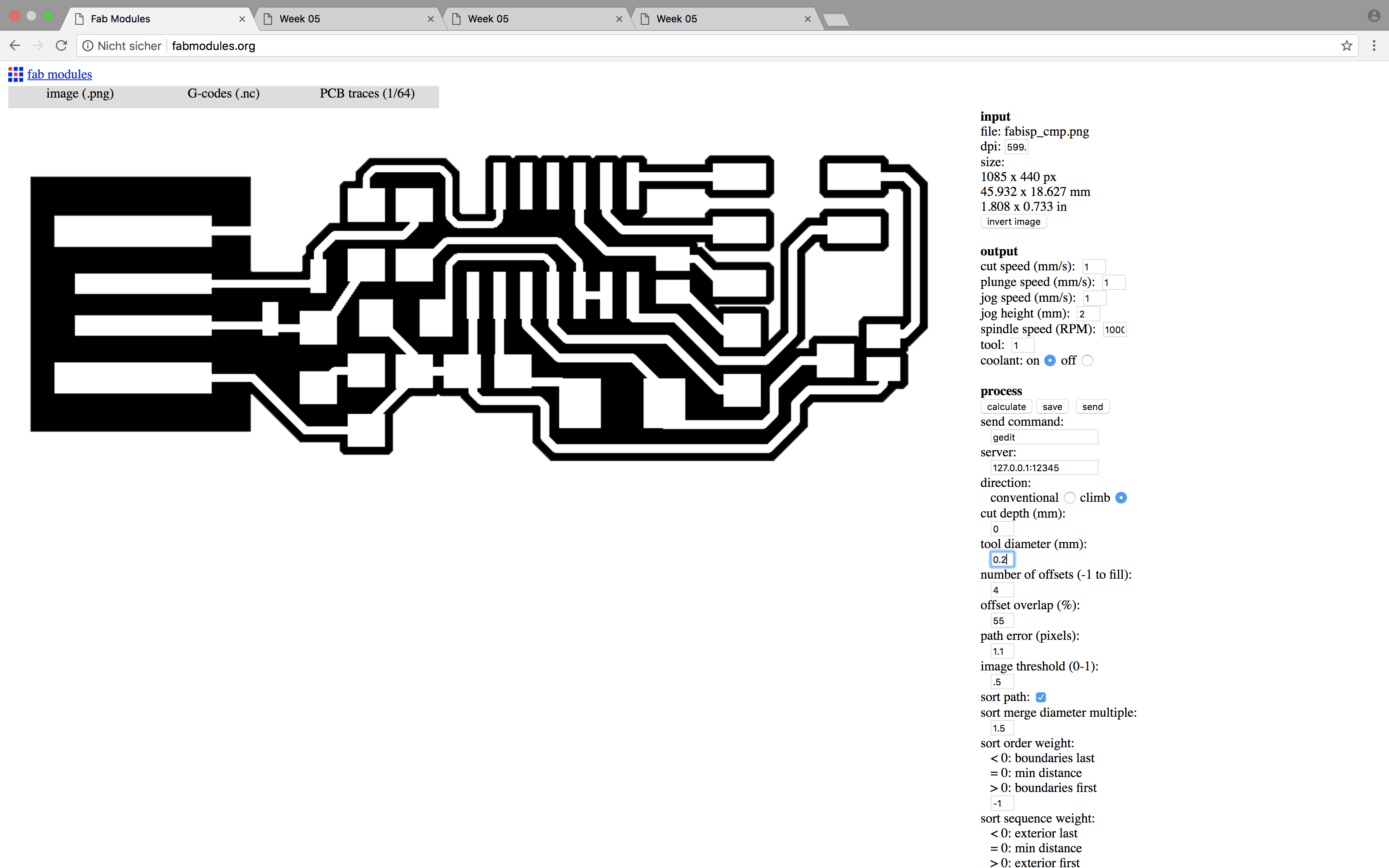
Before sending those designs to the mill, they needed to be converted on fabmodules.org. To fit the job to our machine, I converted Andy's .png-files into G-code. Regarding the previously tested mill properties, I made the following adjustments:
|
Adjustments in output parameters:
|
Adjustments in process parameters:
|