Making controller board
Designed original board dedicated to the project by adding components on basic Satshakit.
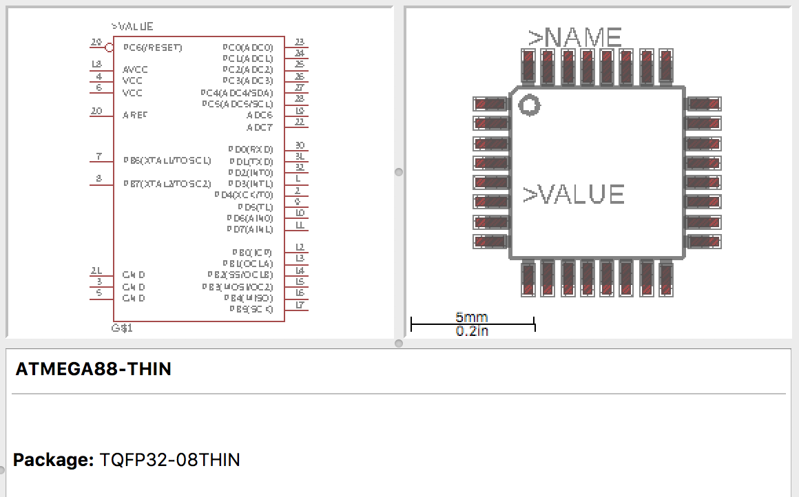
Satshakit uses AVR architecture specifically Atmega328P-AU. Here is the datasheet I refered to:
Download files
-
For complete list of component refer to BOM
Rough sketch
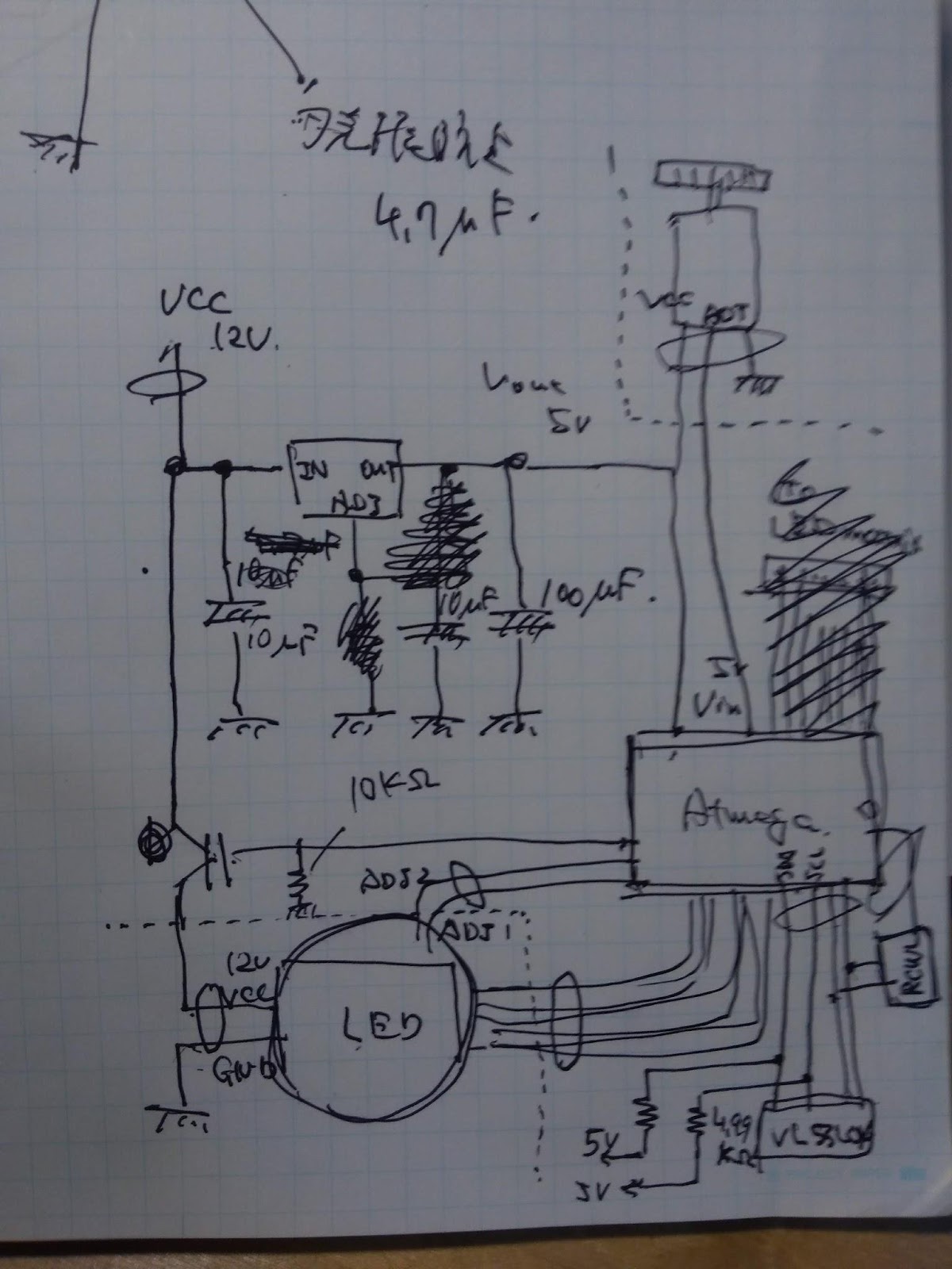
I know it looks awful, but I first did a rough sketch to clarify what am I trying to do.
The components I am adding to Satshakit
Power conditioning
Drop 12V coming from switching power supply to 5V for microcontrollers and sensors using a regulator.
Regulator : ZLDO1117G50DICT-ND 1A-5V (Fablab inventory)
https://www.diodes.com/assets/Datasheets/ZLDO1117.pdf
Typical application

*ZLDO1117G50 Vout will be 5V when ADJ pin in the middle connected to GND directly.
I added diode in case of sudden power loss. The charge on 5V side capacitors could instantly flow backwards at the power loss of 12V side through the regulator and it might damage the component.
In the first place, I was planning to use 1A schottky diode (641-1331-1-ND) from inventory as I thought it has enough capability to handle high current, but later I discovered schottkies have leak current on reverse direction.
So will use 1N4148W switching diode. Its forward max current rates 300mA and seemed bit low, but it was the only SMD diode we had in our lab.
Power switching for LED driver
Receive DC 12V from the AC-DC converter, forward it to LED via MOSFET for turning on/off by microcontroller.
MOSFET : RFD16N05LSM9ACT-ND 16A-50V (Fablab inventory)
https://www.fairchildsemi.com/datasheets/RF/RFD16N05LSM.pdf
I am adding this component to avoid LED driver pump max current into the LEDs during a few seconds right after the power supplied (microcontroller, which is used to regulate IC by sending PWM to ADJ pin, needs few seconds to boot).
My plan was to add open drain MOSFET at the GND line coming back from LED driver, so that I could switch on/off MOSFET with the drive voltage of the microcontroller.
However, what would happen on IC in such circumstances(GND floating etc.) was unpredictable, so I experimented on this before I start to make board.

There was an issue that LEDs slightly light up when putting PWM on ADJ pin. LEDs get brighter as PWM gets closer to LOW state.
The reason of this was current going backwards through ADJ line to microcontroller and it was not good.
My instructor advised me to add diode in the line and it fixed the problem.
1N4148W switching diode
http://akizukidenshi.com/download/ds/diodeinc/1n4148w.pdf
Connectors for peripherals and power
-
Terminal block for 12V input
-
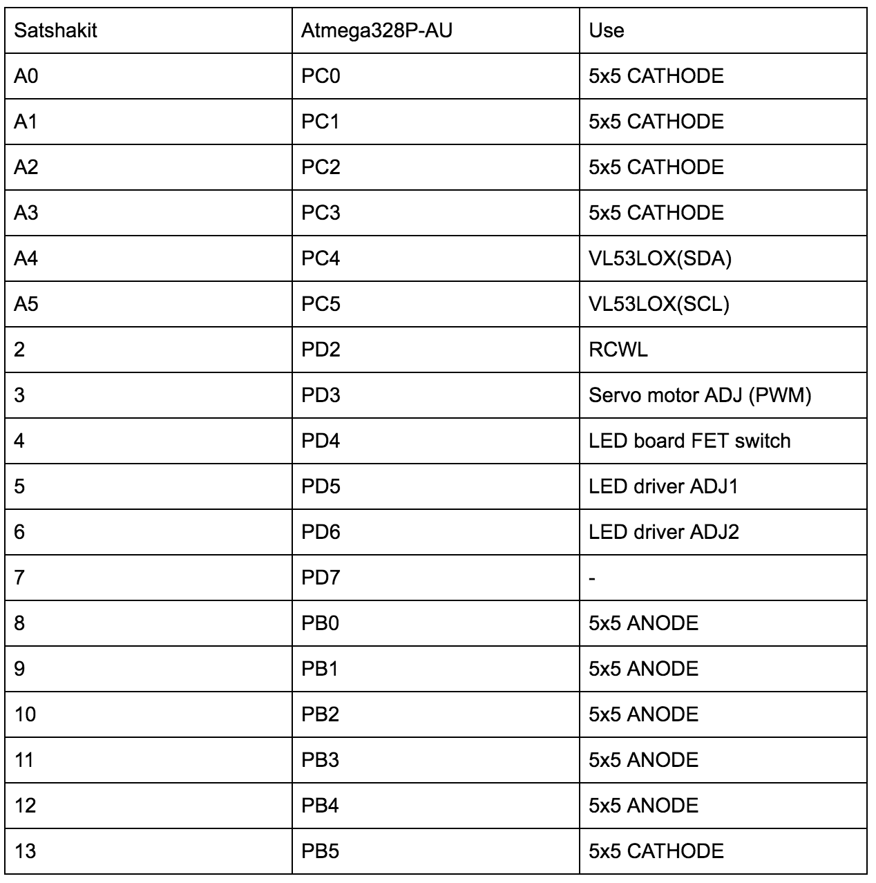
VL53LOX :VCC / GND / SDA / SCL
-
RCWL-0516 : VCC / GND / 1pin
-
LED matrix anode and cathodes : 10pins(5+5)
-
LED power : VCC / GND
-
LED driver ADJs : 2pins (1+1)
-
Motor :VCC/GND + 1pin
VL53LOX (ToF range sensor)
Using I2C protocol to communicate with the controller board.
I2C SDA SCL bases should be pulled up.

The minimum pull-up resistor value can be decided by the equation:
Rp > (Vdd-0.4)/3mA
Rp = pull-up resistor , Vdd = Power supply voltage
When 5V, approx Rp > 2KΩ
Decide the maximum value to meet the sufficient pulse rise time.
At 400kbps communication speed the rise time should be faster than 300 nsec.
Assuming stray capacitance of the bas is 100pF,
Rp < 300nsec/100pF = 3kΩ
Therefore,
2kΩ < Rp <3kΩ
I decided to use 4.99KΩ (from inventory, the most approximate) as a pull-up resistor.
Secure pins to burn bootloader and load sketch
Aside from the peripherals that I am adding, I need to make sure that the pins for burning bootloader and load sketch are in convenient place.

Figuring out the pins
Atmega 328P-AU Pin assignment

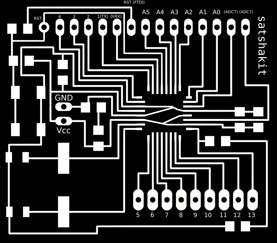
Satshakit schematic
Pin assignment
Drawing schematics on Eagle
libraries
Crystal
https://github.com/chiengineer/Eagle-Libraries/blob/master/Clocks-Crystals-RTC/crystal.lbr
Atmega
*should be this link.
Schematics
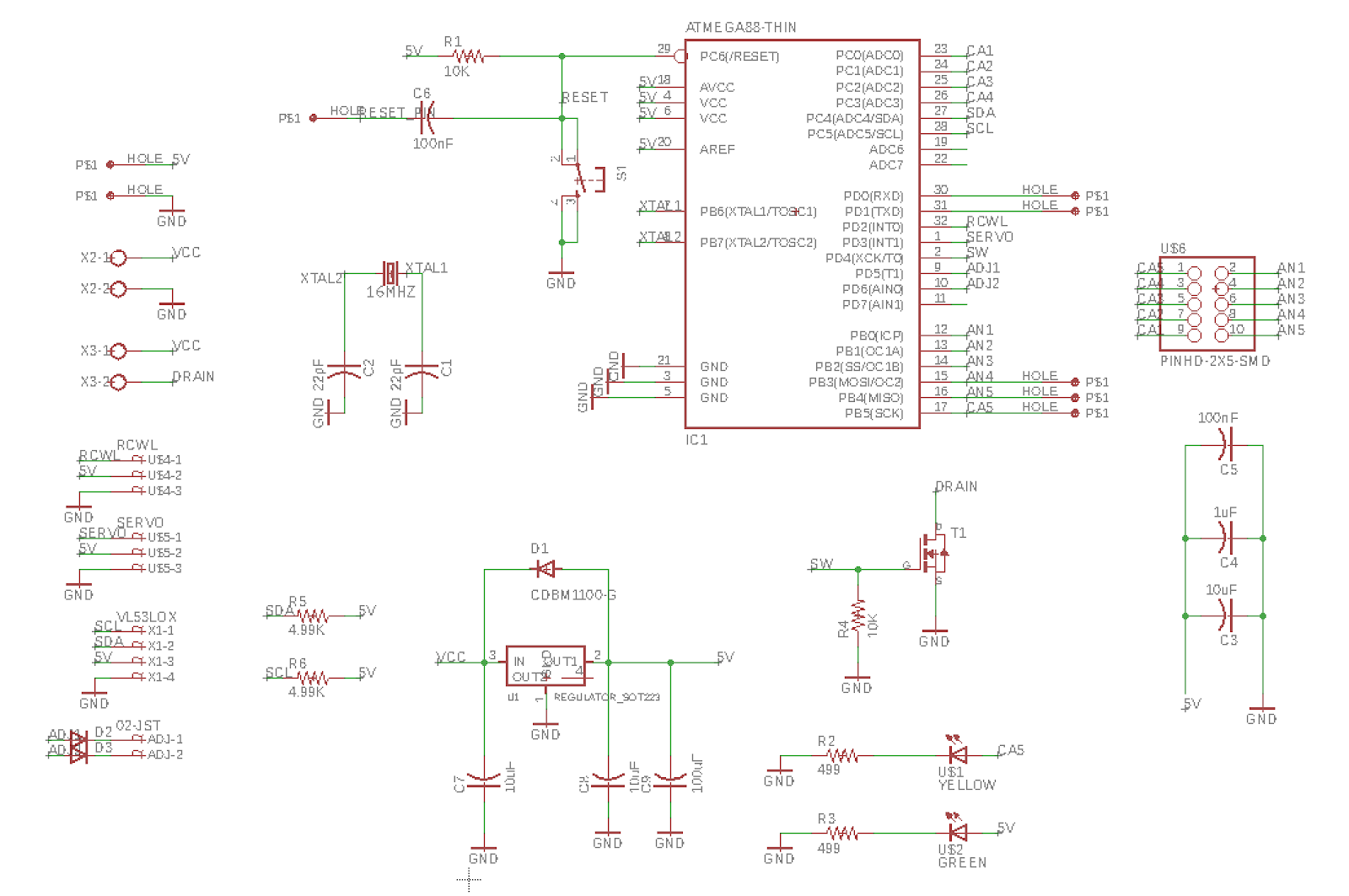
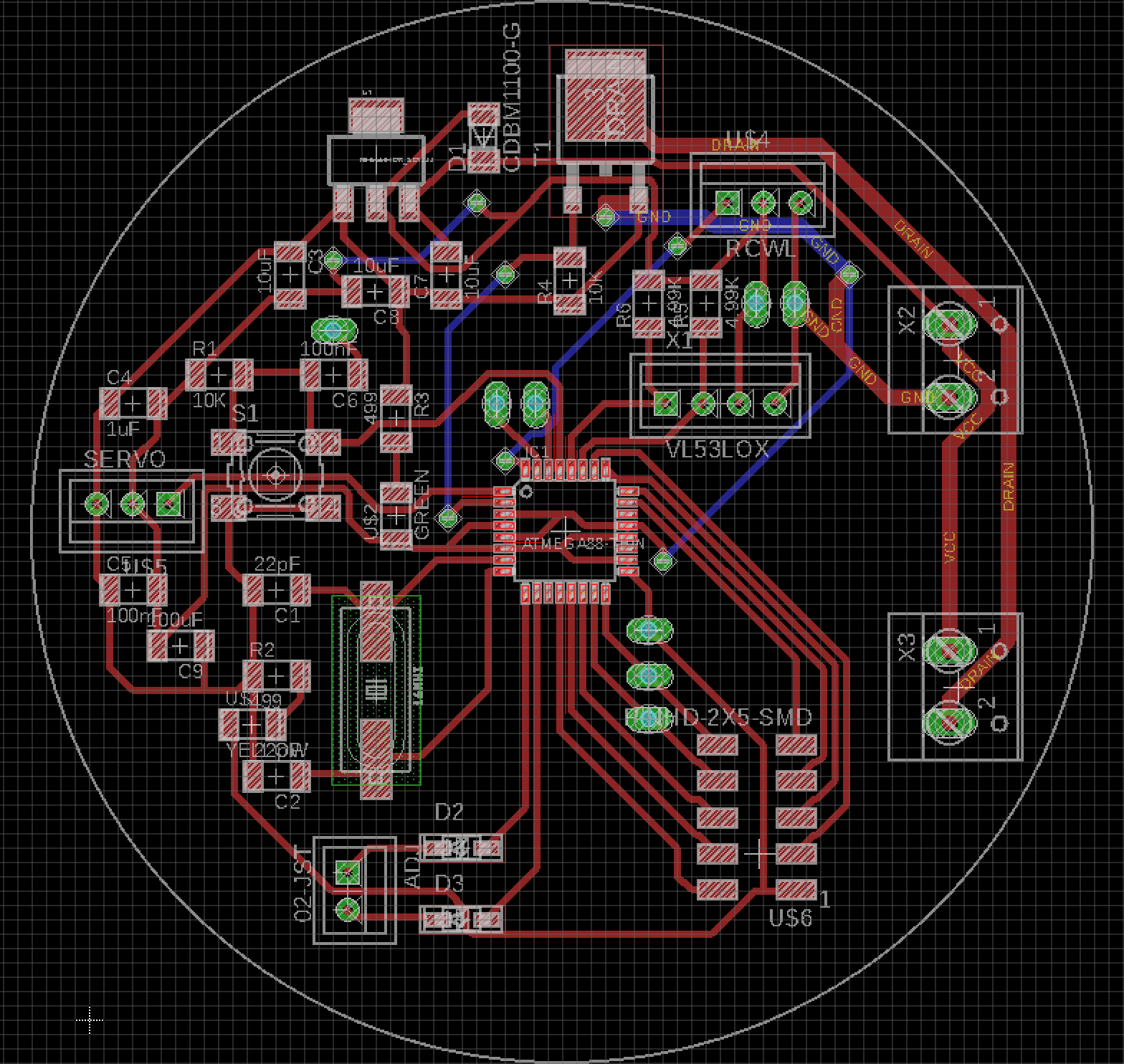
Board
Ordinary traces are in 0.4mm. I doubled the width of the trace for power LED circuit.
Milling and assembling
Mods setting
-
Traces
1/64 tool
The tool size changed to 0.0135 inch -
Outline
1/32 tool
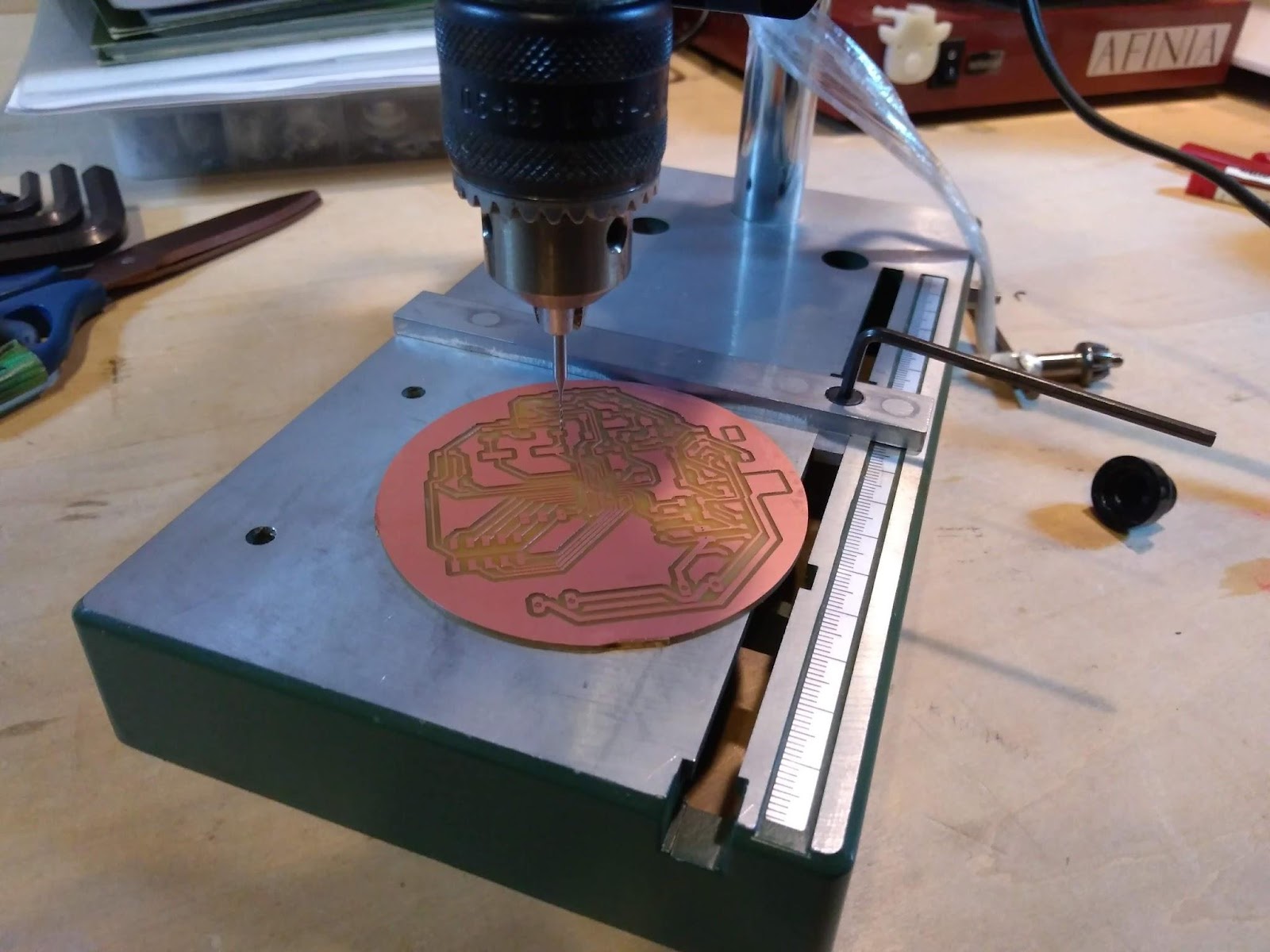
Milled out traces and outline using SRM-20, tool path file(rml) generated with Mods.
Made through holes with drilling machine
-
Pin connectors : 1mm
-
Terminal blocks : 1mm
-
Pin headers : 0.8mm
-
Vias : 0.5mm
Soldering components

Bottom layer routings
I routed the bottom layer wirings with tinned wires on the back side of the board.
*Marked position of the pin sockets first to avoid any conflicts.

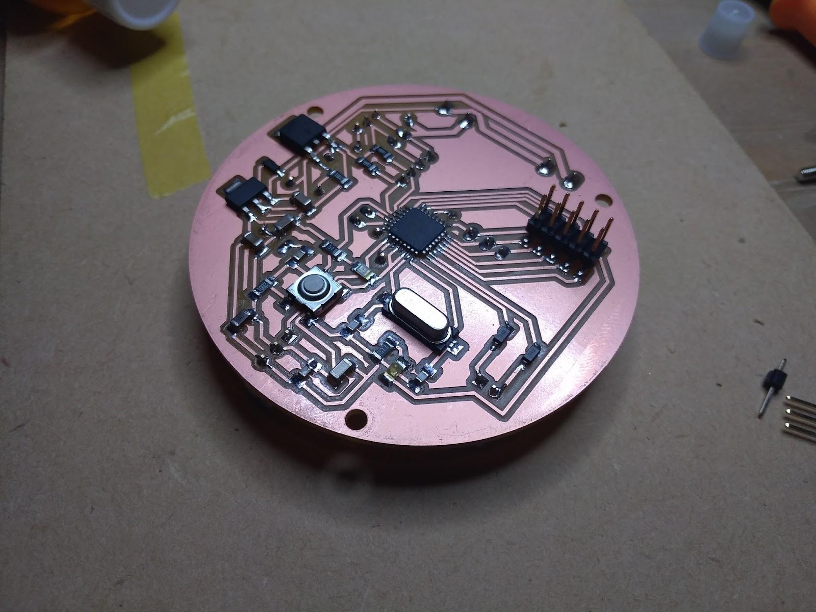
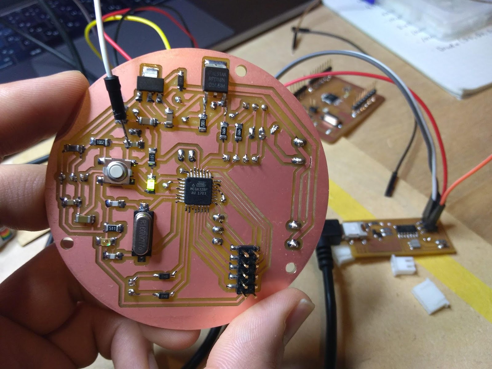
Front face of the board (Mainly microcontroller and other components. A ten pinheader is for LED matrix).
Back side of the board (mainly connectors and some wirings).

Burning bootloader
Refering to Satshakit instruction , the microcontroller will become programmable by Arduino IDE once a bootloader burnt.
Following the instruction:
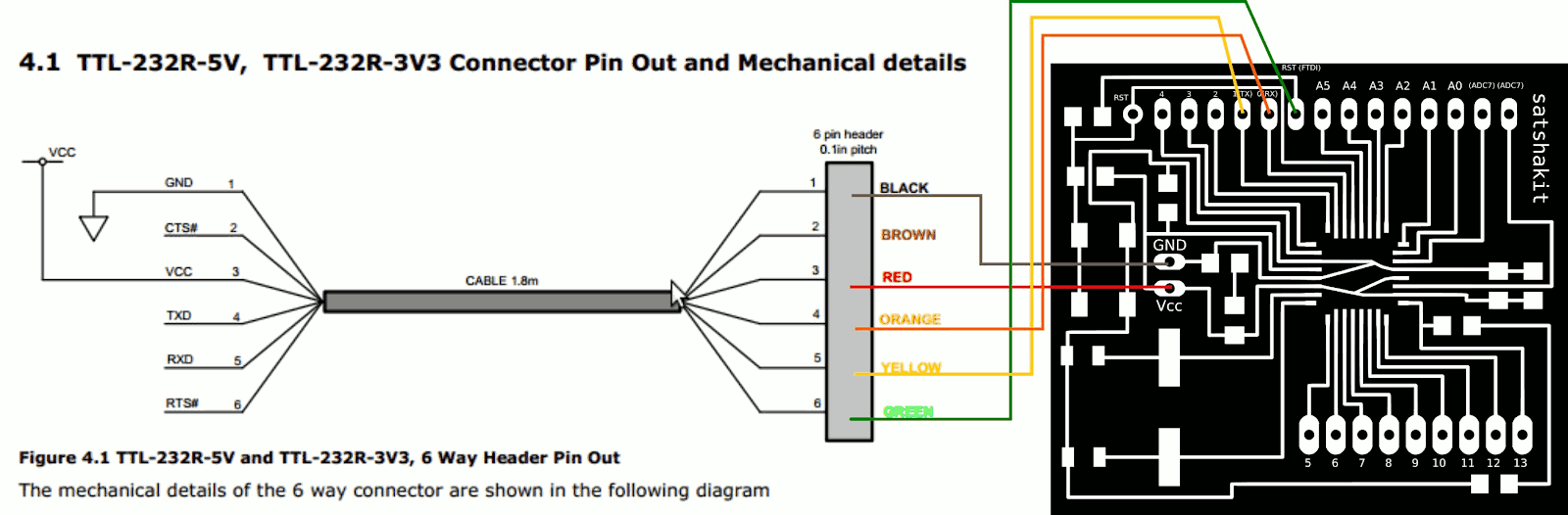
I used FabISP to burn bootloader to my controller board. First wired FabISP and the controller board as this schema, then
-
open Arduino IDE
-
select proper programmer by clicking on Tools->Programmer (for example USBtinyISP)
-
select Arduino UNO as Tools->Board
-
click on Tools->Burn Bootloader

Once bootloader is loaded, I no longer need FabISP to program my board. I tested programming it with sample blink sketch using FTDI cable and it worked.
Problems I had to fix during the attempt to burn bootloader
Issue:
Arduino power indicator LED immediately turns off as I connect gnd and power line.
Causes / solutions:
I checked resistance between VCC and GND pin and turned out it was a short circuit.
I found the part where is not milled properly. Shaved some copper to separate those lines with ultrasonic cutter.

Issue : Solder failure
Tinned lines were not well soldered enough to make firm contact at the surface layer.
Issue : Still cannot burn bootloader
Causes / solutions :
Reset line supposed to be connected directly to the reset pin of the microcontroller when burning bootloader, but I only had connected via capacitor which is used when loading program to the board. So I had to temporary jumper wire bypassing the capacitor which made burn bootloader successful.
Test run!!!
Servo
Working, but still have a lot to figure out.
It does rotate and I can (somehow) adjust its rotation speed by giving 0 to 180 value with analogWrite command to the dedicated pin.
However, I don’t know how to stop it or stop it at the desired point.
LED matrix
Working perfectly. Stunning!
Power LEDs and heat sink fan
They lights up as I expected but seems dimming is not working.
VL53LOX (ToF range sensor)
Working absolutely! Running in Long Range Mode but the speed and accuracy is just fine. It could read 0 - 1200mm range fairly accurately.
RCWL (radar human proximity sensor)
Working properly. It backs digital value (0 or 1). 1 if it found people movement around it, 0 if nobody is moving.
IMPORTANT NOTE
When connecting PC to the board to program it, DONOT leave PC connected to the board for long time if the controller programmed to turn on the FET switch (sw). High loads(such as power LEDs) on 12V side try to draw current from 5V side and it might destroy regulator, even though I placed diode to let current flow detour the regulator. However, the diode max current rating is not very high (somewhere around 600mA).
Programming
What is accomplished and what is not
I wrote a program by combining following functions that is already accomplished.
-
Dimming LED (simple PWM and toggling switch to turn on/off the LED driver)
-
LED matrix (using pulse drive)
-
VL53LOX (from library : #longrange mode, #highaccuracy mode)
-
RCWL (simply reading digital value sent from the RCWL board)
What I haven’t accomplish is to read VL53LOX while LED matrix is presenting indicator.
I guess it could be done by interrupt of Arduino IDE, but I need to catch up with it.
Here is current version of the program: