LED board
I was planning to make two separate LED board for power LEDs and LED matrix for projection in the first place. However, I discovered there is no need of moving those two LEDs separately as LED matrix will be turned off when power LEDs are discharging light. Therefore, I am designing big one LED board integrating power LEDs, LED matrix and LED driver all together.
Download design files
-
For complete list of component refer to BOM
Components
-
R1 (Rsense) : 0.1Ω resistor
Download Eagle lbr for 3225 smd chip from
https://www.diymodules.org/eagle-show-library?type=usr&id=2146 -
R2 (pull down resistor for FET gate) : 10KΩ
-
MOSFET(open drain circuit for PWM dimming) : NDS356APCT-ND (Fablab inventory)
-
C1(power), C2(LED) : 4.7uF, 1uF (Fablab inventory)
-
D1 : 641-1331-1-ND (Fablab inventory)
-
L1 : 47uH
-
CL6808
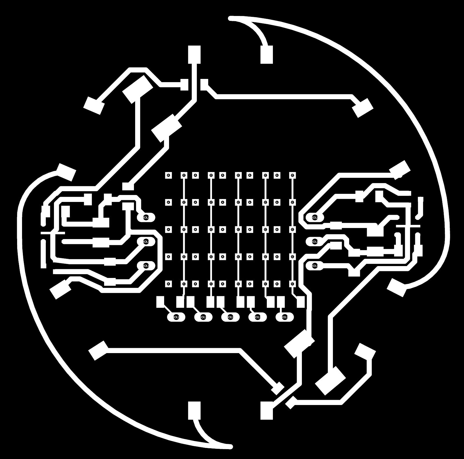
Design board
I used relatively wide paths to route power LED VCC and GND patterns.
Pattern width : 0.8128 (power LED circuit) / 0.254 (LED matrix circuit)
Putting all components into small space is mind wrecking experience (as usual), however I managed to fit all the components. I had to use jumper 0Ω resistor twice.

Milling
Trace
Holes for 3W power LEDs

Note
-
Used Mods to generate tool path(rml file).
-
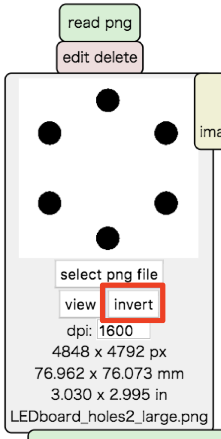
Invert image as Mods considers white as the part to remain.
-
Milled with 1/32 tool.
Marking for LED matrix and pads.

Note
-
1/32 is too big for this size of through holes but making hole with 1/64 tool was a challenge, so I decided to mark (drill slightly) the position of the through holes with SRM, then drill hole using a hand leutor.
-
Again, don’t forget to invert image in Mods.
Outline


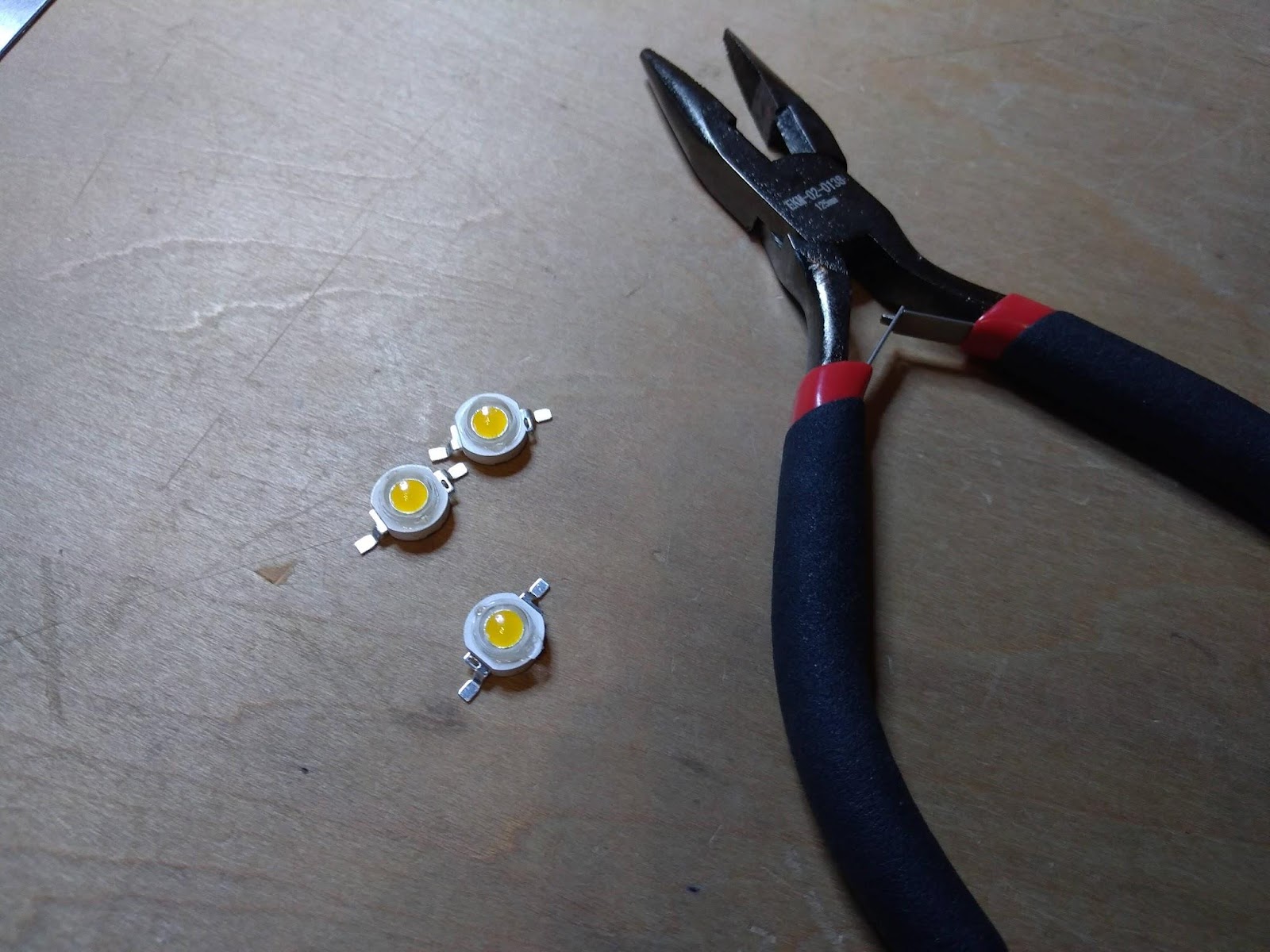
Assembling components

The legs of the power LEDs supposed to be bent to fit the holes.
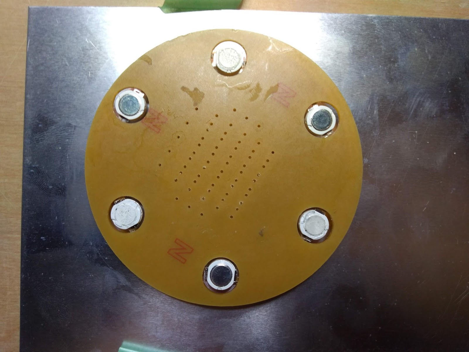
The opposite side of the board.
Thermal conductive part (metal part) of the LED should have perfect contact with heatsink aluminum. I used thermal conductive silicone glue to achieve this.

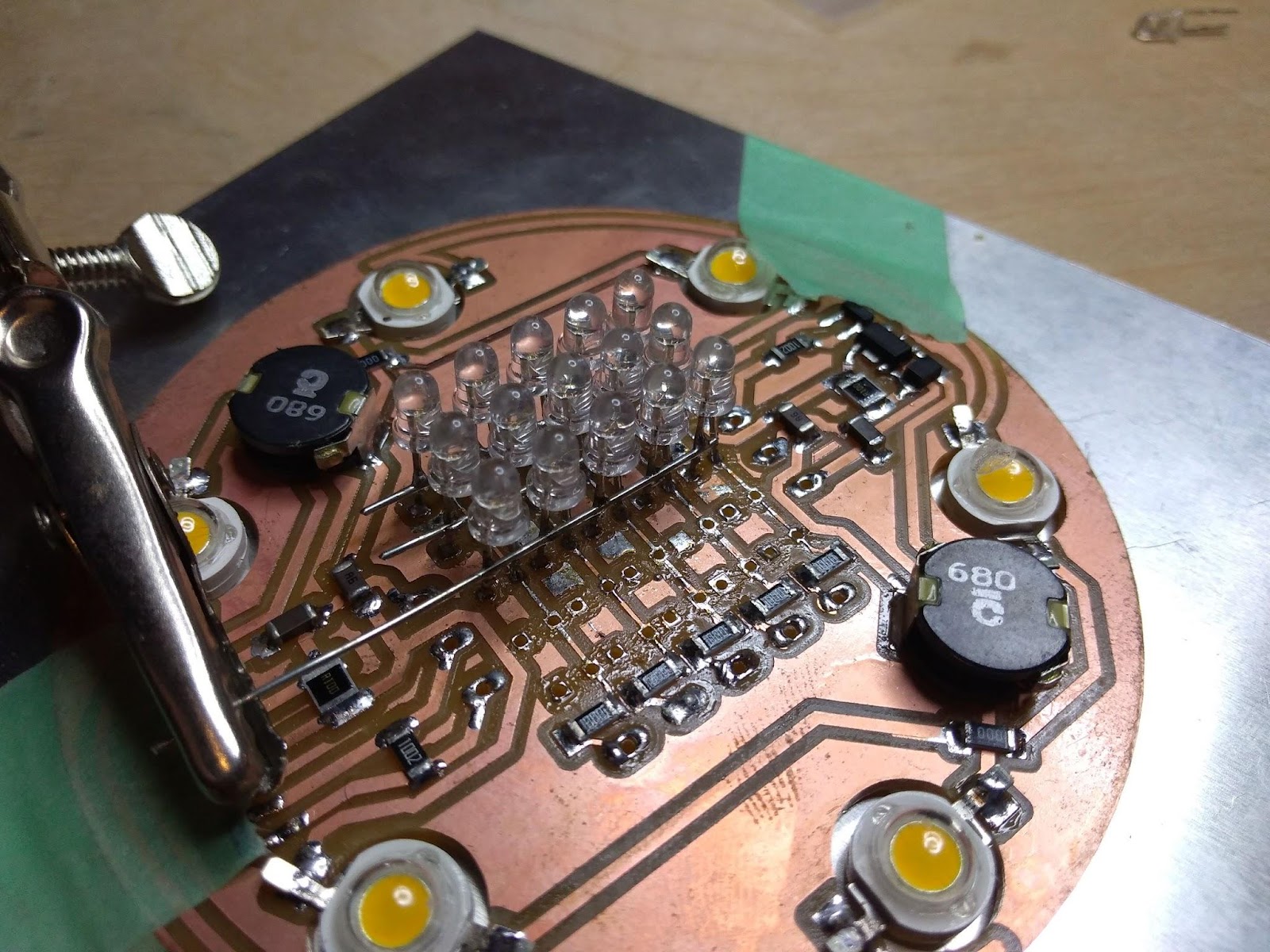
LED matrix
Fabrication of the LED matrix
Schema of LED matrix


Column lines implemented within the board are dedicated to LED cathodes.
Row lines are dedicated to LED anodes and should be connected in the air. (It supposed to be much easier in the initial plan : wire anodes on the back side of the board, but changed plan to use the whole back surface as a heatsink due to the result of heat experiment*)
*Heat experiment could be found at the bottom of this document.
I did this by soldering small jumper wire between each anode pins and it was a nightmare.
Issue : LED did not meet the requirement (FATAL)
The initial problem I was facing was this.
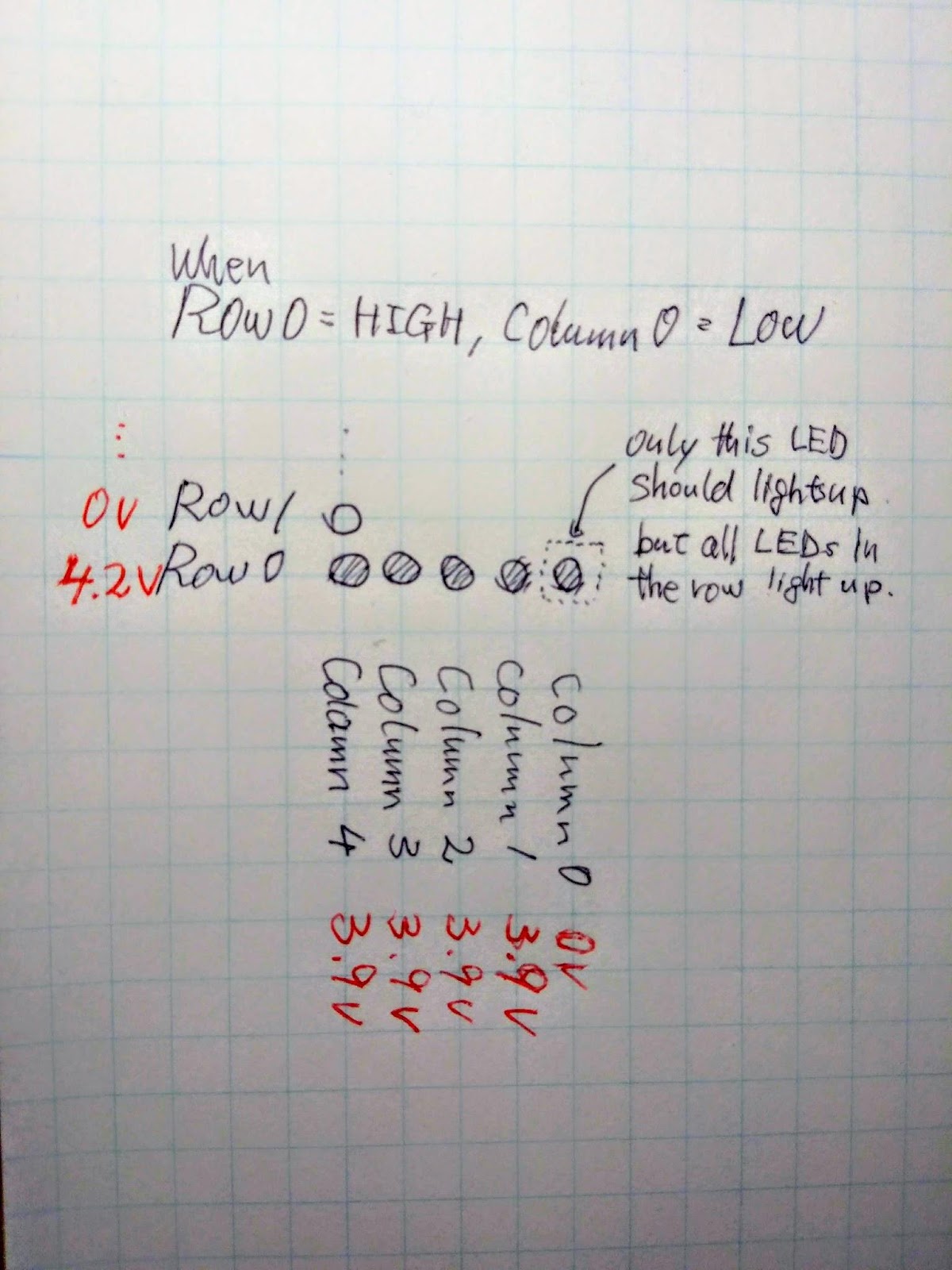
Eventually came out that LED is somehow not working properly.
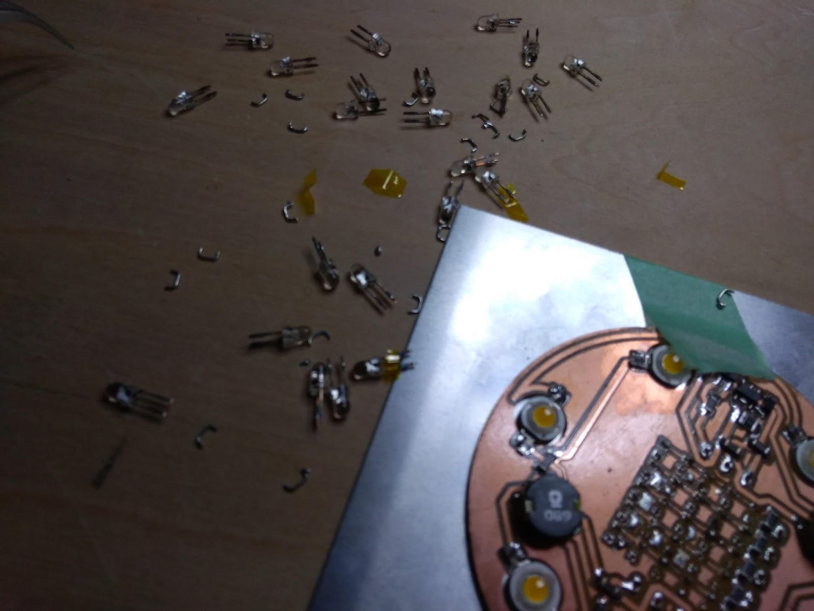
I have never seen such LED before but the anonimus LED I grabbed from Fablab stock had diode in it to let the opposite current flow. As I was planning to use charlieplexing to drive LED it shouldn’t allow current flow another direction, so I had to redo them all… after 3 hours of struggle…
Redoing everything
However, I came up with a better idea in the second time of the anodes soldering.
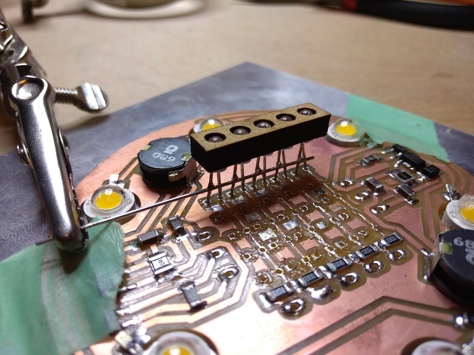
I made this jig with a laser cutter to align LEDs(led_guide.pdf).
Slightly twist the LEDs to get anode in the front and back off cathodes. Then solder simple wire at once.
This process saved my time A LOT.
Programing
Arduino sketch
Borrowed and modified sketch from here:
5X5 DOT MATRIX ON ARDUINO (GETS TEXT FROM PC) FULL INSTRUCTIONS AND SCRIPT
http://www.instructables.com/id/5X5-dot-matrix-on-Arduino-gets-text-from-pc-2/
Problem
Issue : Some row pins not responding
Column pins seemed fine, but some of the row pins could not be set to HIGH or LOW in the program.
In order to clarify the problem, added line to show the actual value of array valuables.
void setup() {

Serial.begin(9600);

for (int i = 0; i < 8; i++){

pinMode(rowPins[i], OUTPUT); // make all the LED pins outputs

pinMode(columnPins[i], OUTPUT);

digitalWrite(columnPins[i], HIGH); // disconnect column pins from Ground

Serial.print(columnPins[i]);

Serial.print(":");

Serial.println(rowPins[i]);

}

}
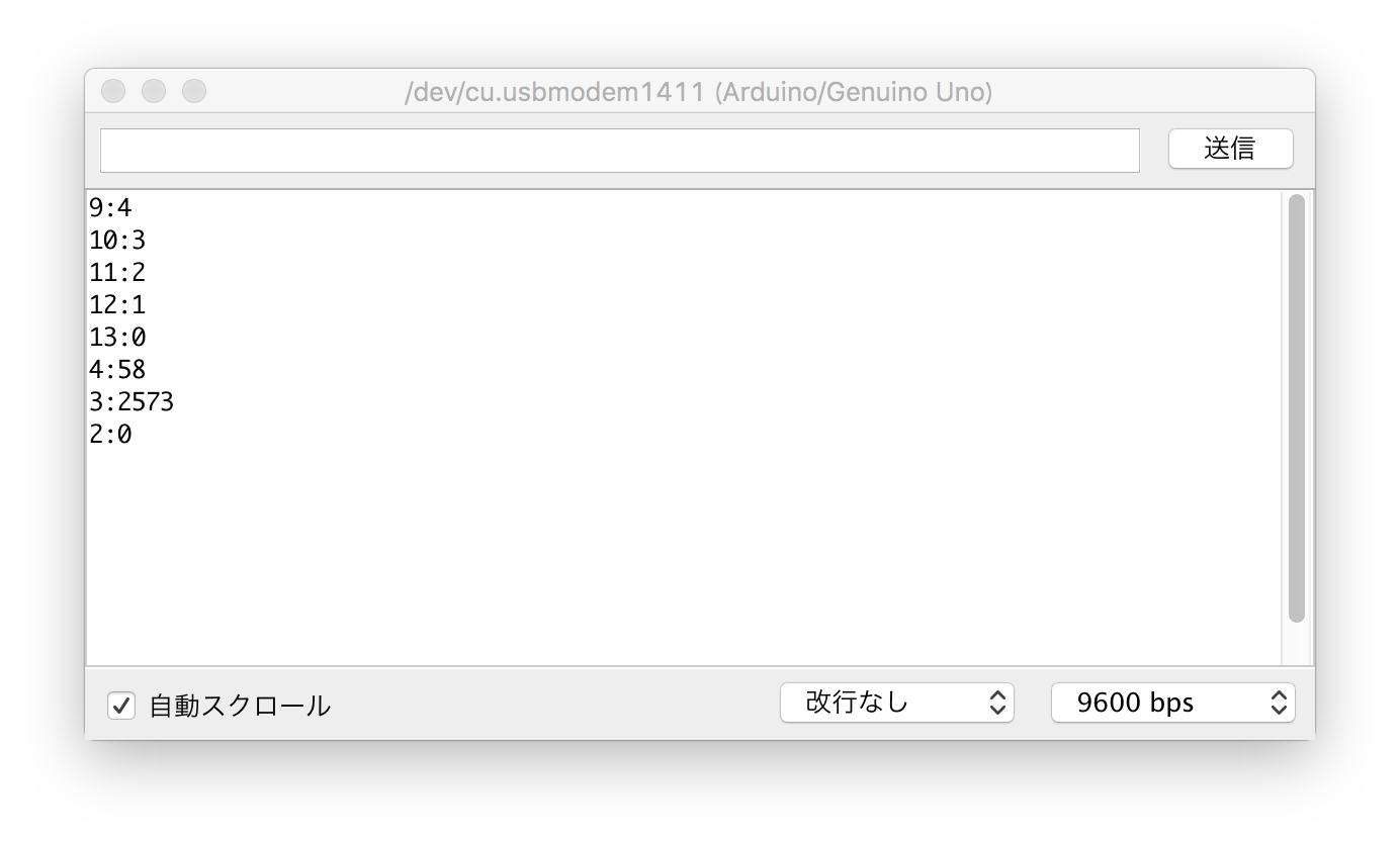
Turned out array variable returns weird value when index number does not exist.
Fixed code.
void setup() {

Serial.begin(9600);

for (int i = 0; i < 5; i++){

pinMode(rowPins[i], OUTPUT); // make all the LED pins outputs

pinMode(columnPins[i], OUTPUT);

digitalWrite(columnPins[i], HIGH); // disconnect column pins from Ground

}

}
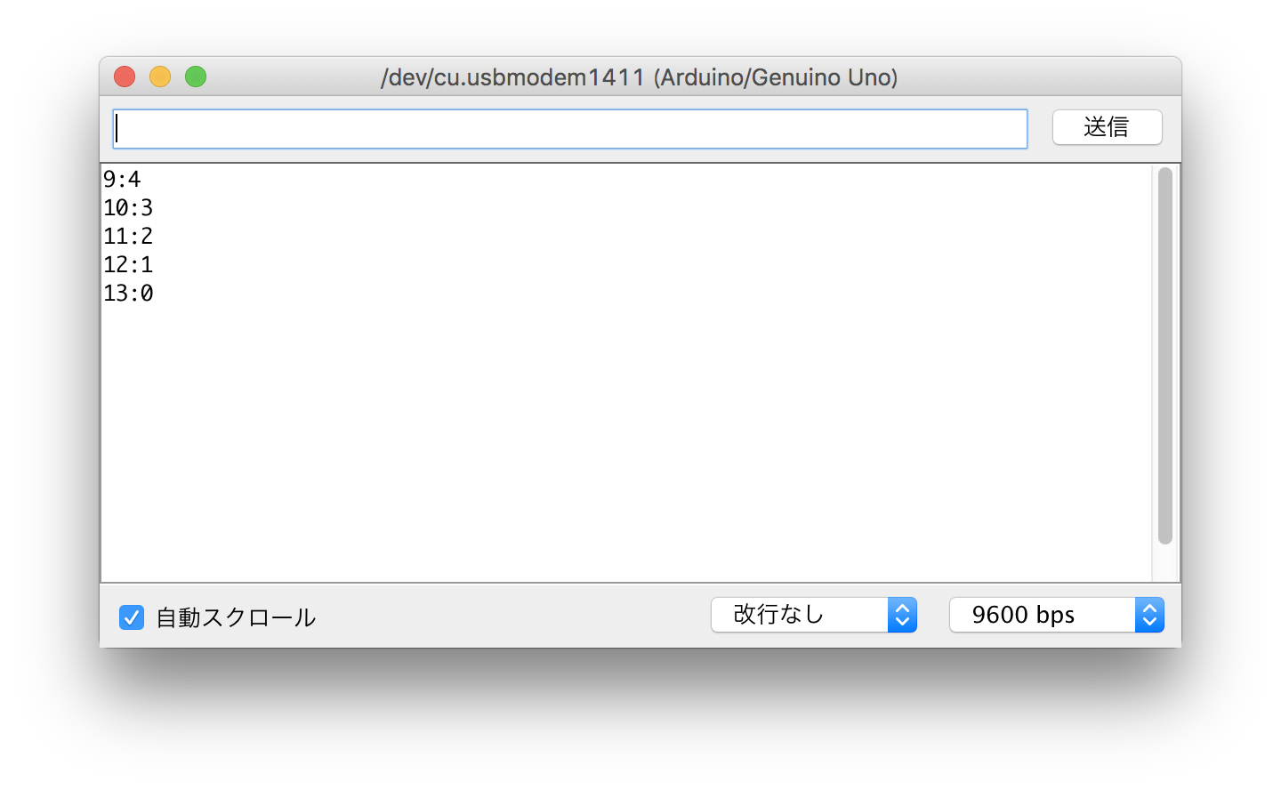
Looks OK.
Heatsink
Experiment on power LED radiation
I was planning to fabricate my own heatsink with aluminum beforehand, so I run a test to know how much mass of aluminum is needed to draw heat away from 6 power LEDs.
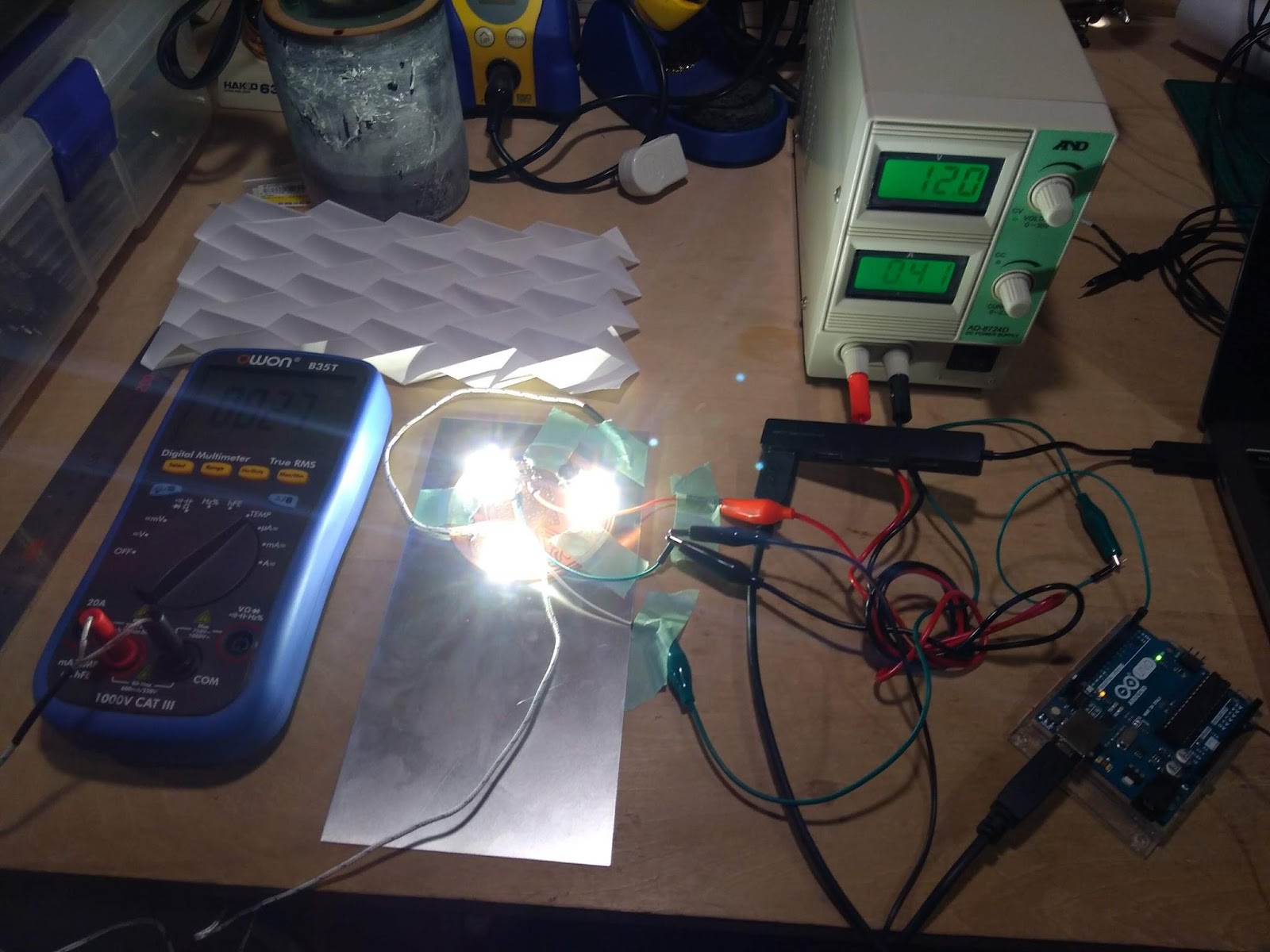
Put LED board to 200x100mm 0.5mm thick aluminum board, and used silicon heat glue to attach LEDs to the aluminum.
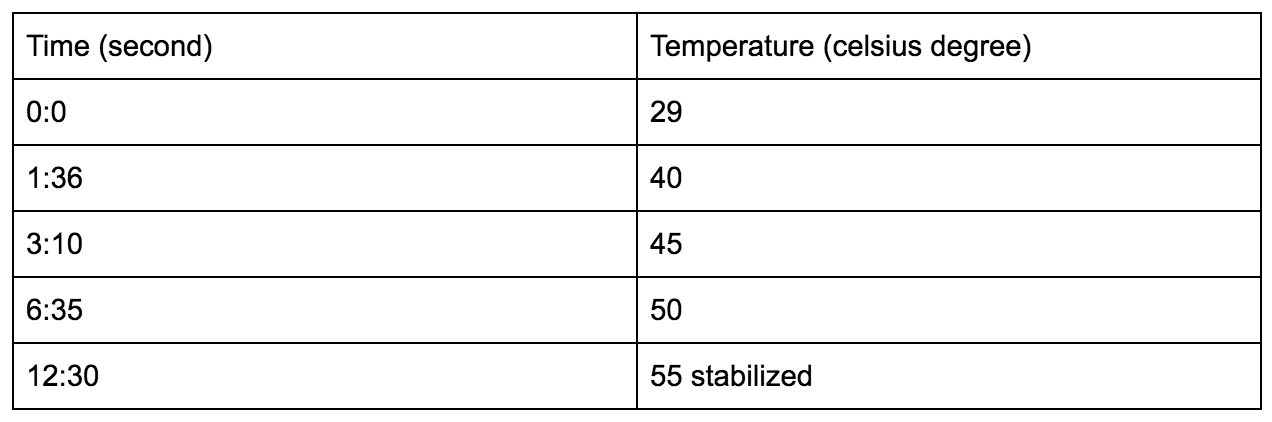
Result
- 3W LED x1 / 12V 420mA
- 3W LED x3 / 12V 420mA
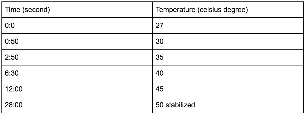
Decided to use ready-made heatsink.