final project development
assignment
-
Complete your final project, tracking your progress:
- what tasks have been completed, and what tasks remain?
I've finished what I have planned (except for going surfing). - what has worked? what hasn't?
GPS location and temperature data were successfully logged in an SD card.
- what questions need to be resolved?
waterproof verification - what will happen when?
- weekly assignment cutoff: due 11 June
- final presentation: 20 June - what have you learned?
A lot of things, including 2d/3d design, CNC, PCB design, electronics, time management. I've got a kind of sense that I might be able to make (almost) anything.
tracking my progress
January
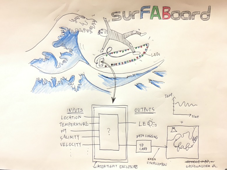
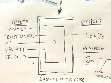
In first week assignment, I drew a rough concept of my final project. I want to make a surfboard with various sensors to measure the oceanographic data. It is a kind of an ocean version of Smart Citizen.
One thing I'm sure was its name, surFABoard, but about other many things, I'm lost. How many sensors can I use? How do I connect those sensors? Can I have sensors for my purpose? Which microprocessor do I have to use? How about waterproof? Do I make a surfboard itself or just sensors? If I make a surfboard, how can I do?
February
After Fab Academy began, I could think of nothing but an assignment. I was overwhelmed by weekly assignments. Neil often recommended that we make a component for our final project in each week, but I've got my hands full with only a task of each week.
March
surfboard (Week 8: computer controlled machining)
Time flies. Nearly half of classes have finished. I guess I still keep up with the pace with the progress of classes, but I haven't make a thing for my final project. In hindsight, this week was a kind of big turning point for me.
I waited to decide whether to make a surfboard or just put sensing components onto my existing board. On the second thought, why did I enroll in Fab Academy? Wasn't it to learn how to make almost anything, right? I made up my mind to make a surfboard.
FabLab Kamakura doesn't have ShopBot, and past FabAcademy students had to go to other facilities this week. On top of that, nobody tried to machine styrofoam. It was evident that people don't like messy styrofoam powders...but, Takemura san, director of FabLab Hamamatsu: TAKE-SPACE, was kind enough to let me try to machine it.
concise descriptions
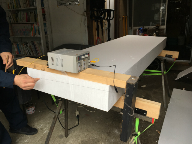
I bought and sent three styrofoam blocks to FabLab Hamamatsu in advance, one was for a test machining, the other was for an assignment, and the last one was for a backup. I had to cut a part of styrofoam with an improvised hot wire foam cutter because it was too thick to be placed on the CNC working stage.
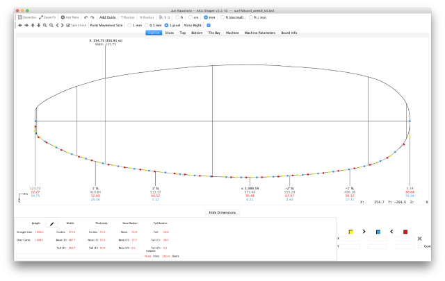
I used a surfboard CAD software, Akushaper. I have designed a surfboard with it in week 3 (computer-aided design) I modified the design's dimensions (shorter length and lower rocker than the original size) to fit the CNC table.
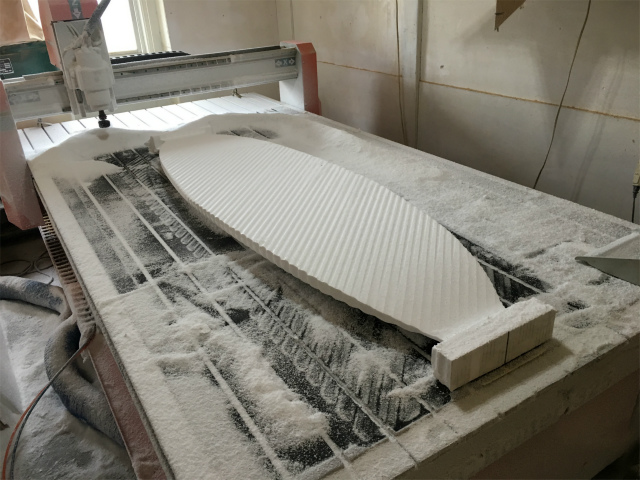
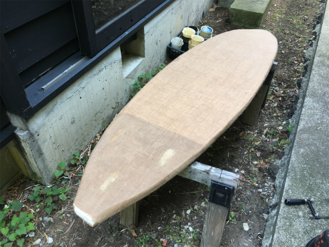
There were considerably messy milled styrofoam powders, but finally, I've got kind of one of the final project components (it still needs FPR coating).
See the detailed description of Week 8
fins (Week 10: molding and casting and final development)
Surfboard fin is the best motif for molding and casting. I designed it with Fusion 360 based on this tutorial. Here is a concise description.
concise descriptions
First, I drew a blueprint of a fin to trace and model.
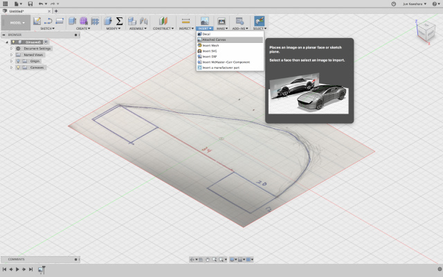
Second, I designed a 3D model of a fin by using Fusion 360.
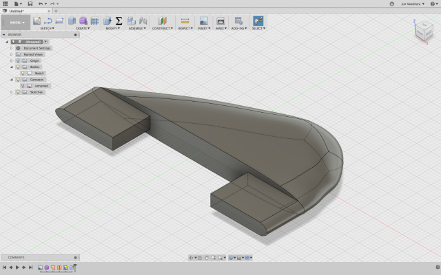
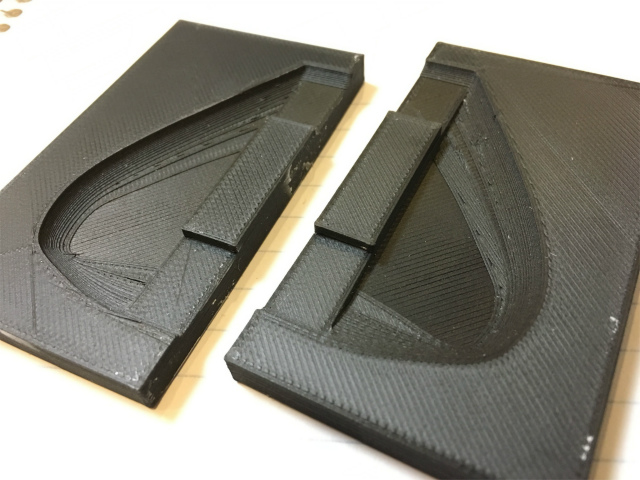
Based on the 3D model of a fin, I made a 3D model of molding.
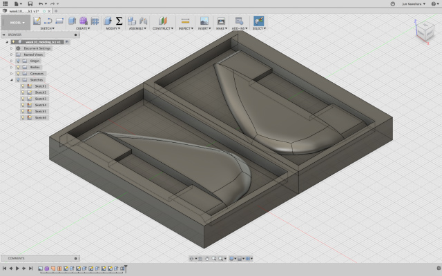
I machined a wax to make a molding.
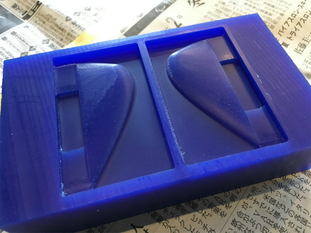
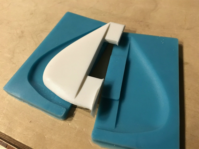
I cast a silicone based material and got molding.

I could make nice and smooth surface fins.
See the detailed description in Week 10
3d-printed fin
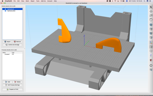
I also made a fin by 3D printing just in case.
I chose the model orientation of the left. Fin legs strength would be stronger than that of the right because of the interlayer orientation.
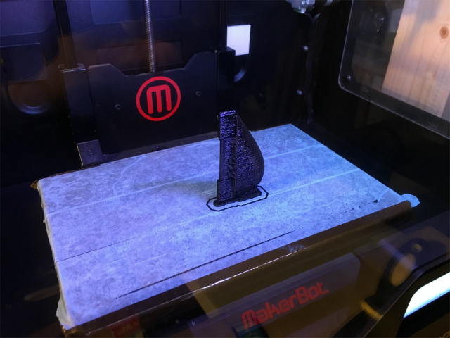
With a raft and a support structure, the printing was done successfully.
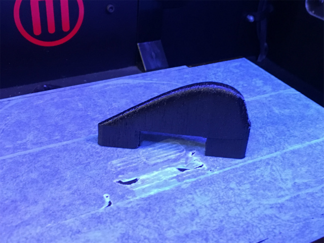
I removed them, and the postprocessing was completed.
3d-printed molding and casting (Week 10: molding and casting)
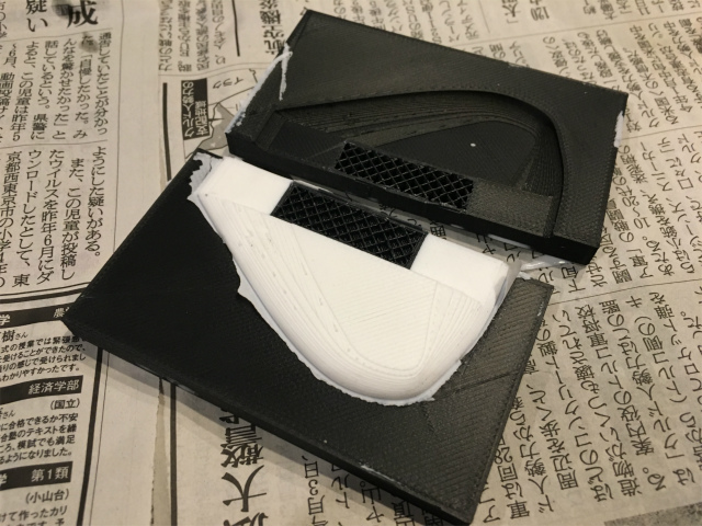
I also made a fin by additively manufactured molding.
3d-printed molding was a little warped, so I pressed moldings with a rubber band.
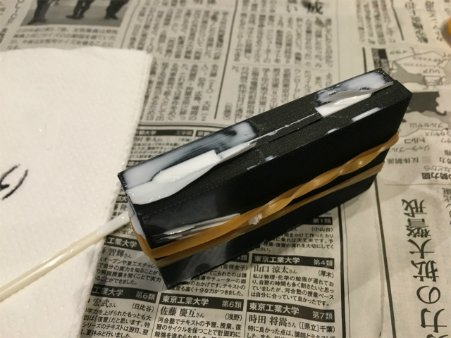
The reproducibility of casting was pretty amazing! Layer lines were perfectly reproduced. It was a casted fin but looked like 3d-printed.
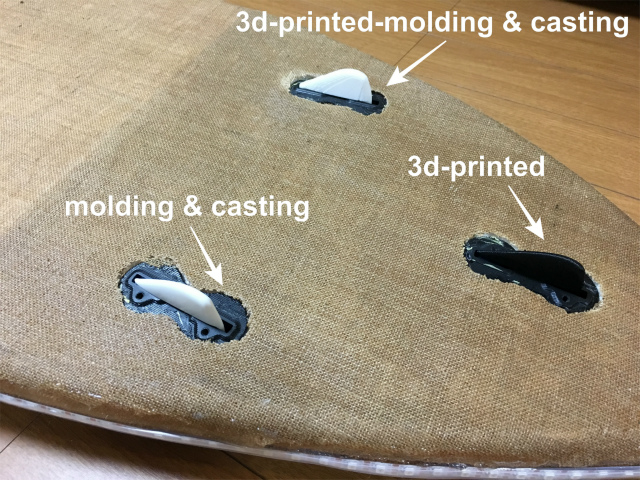
Eventually, I used fins manufactured different processes.
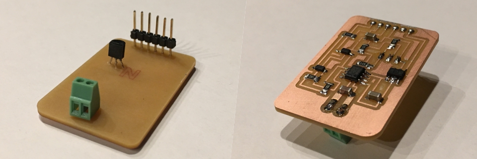
temperature sensor module (Week 11. input devices)
I need a temperature sensor to measure seawater temperature. Neil's example was one for ambient temperature and not suitable for my purpose. I need a thermocouple type temperature sensor.
I was going to use an off-the-shelf module, MCP9600, which was able to communicate via I2C. It was quite obvious that Neil would not like using commercial modules. I tried to make a module but couldn't find a thermocouple converter chip for the I2C. So, I used MAX6675 (and MAX31855, eventually) for SPI communication instead.
I had a bunch of problems in this week.
- burning bootloader
- SPI's chip select pin state
- ATtiny45 doesn't support SPI.h
- memory map difference
I couldn't help but use a commercial module for this week assignment, but I designed a module later based on the module I used.
Here is a schematic,
and a PCB layout.
I confirmed that my ATtiny44 board and a non-commercial thermocouple module could communicate via SPI.
As I wrote earlier, I was going to use a off-the-shelf I2C module. Now that I designed a module myself, I am going to use it for my final project.
See the detailed description in Week 11
April
main board and output (Week 12. output devices)
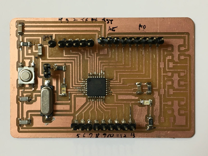
As depicted in an initial final project concept, I wanted to embed LEDs onto the surFABoard to blink colorfully depending on a sensing value, such as temperature, velocity or acceleration, etc. I also wanted GPS data in sensing and data storage. I need a lot of pins more than ATtiny44 or 45 has, which means I need to design a board with ATmega 328P.
I designed my satshakit based on the satshakit CNC and connected it with LEDs with reference to a typical application circuit of LEDs' datasheet.
concise descriptions
Here is schematic.
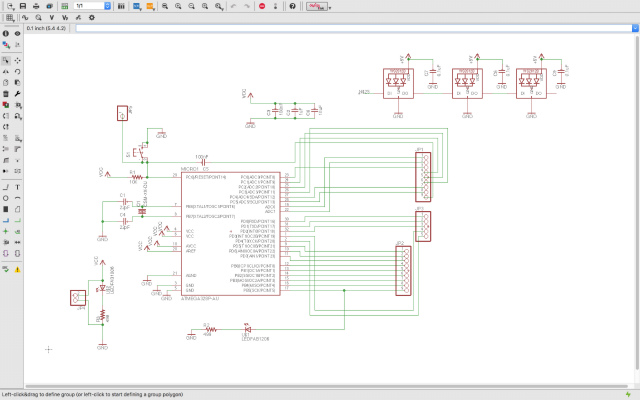
and PCB layout.
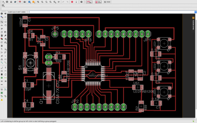
I milled a PCB and soldered all components. After burning bootloader, I verified that my Junino worked fine. I will use this board for my final project.
See the detail description in Week 12
May
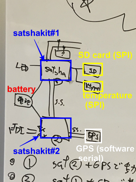
integration concept
Initial concept in January, I had no idea about how many sensors can I use? How do I connect those sensors? Can I have sensors for my purpose? Which microprocessor do I have to use?
A concept around March. I wanted to connect a lot of sensors to a microprocessor and recognized that I2C was suitable for that purpose. I was going to make only a central microprocessor board and use off-the-shelf sensor modules.
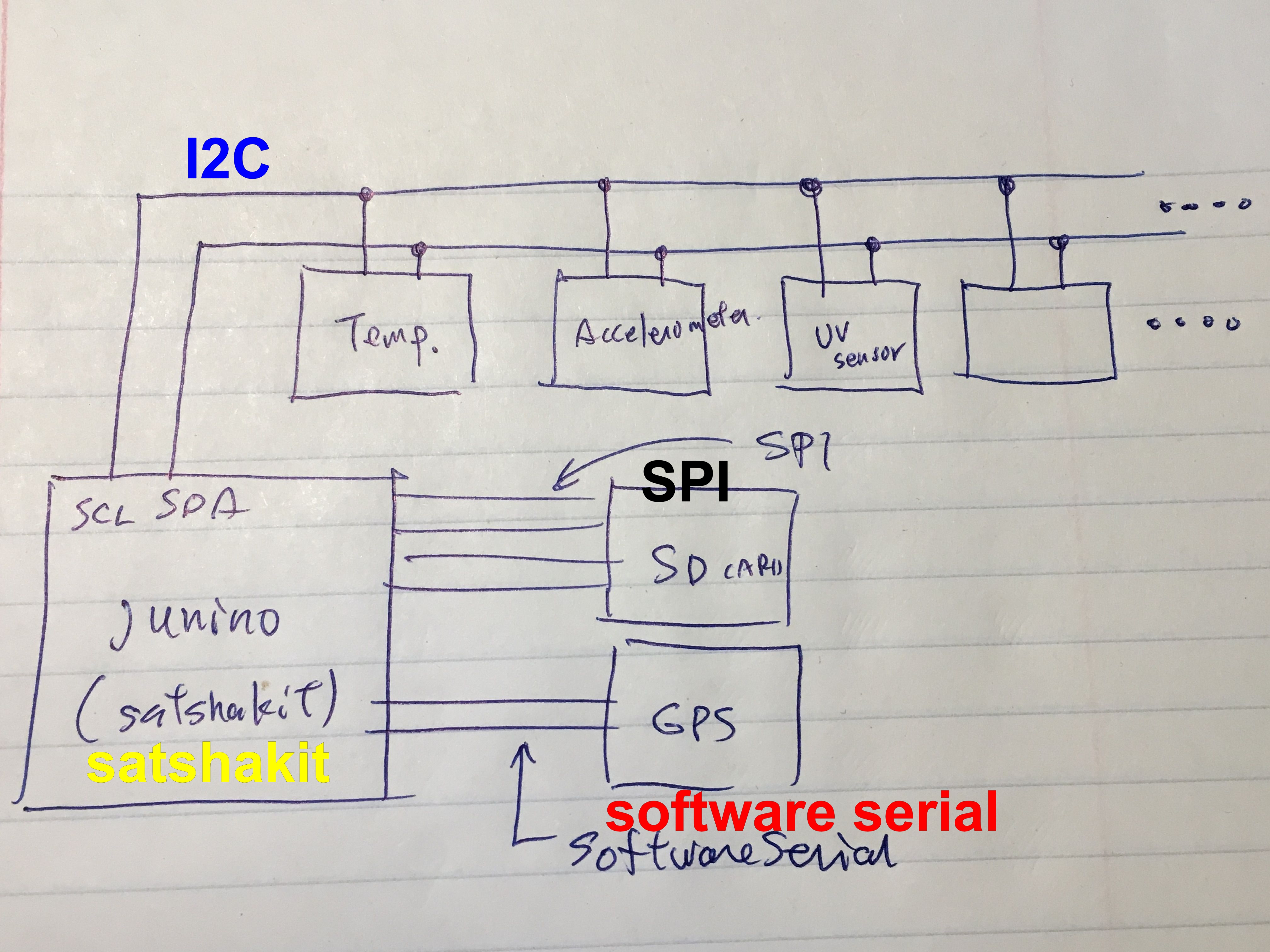
A Concept of the beginning of May. I2C modules have gone. The only off-the-shelf module which I used was GPS module. I never expected I could come this far. The reason I tried to use two satshakits was a memory problem. I2C temperature module's library seemed to consume a lot of memory. In compiling, compiler returned a message, "Low memory available, stability problems may occur."
After I switched I2C to SPI temperature module, the problem has gone, and I didn't need the second satshakit. Eventually, I removed the second satshakit and added power supply module to the third concept.
SPI devices conflict
As I mentioned earlier, I was going to use a commercial thermocouple module. I have already tested that I could store the temperature log in an SD card which was also a commercial module. In that case, thermocouple module could communicate with an Arduino via I2C and an SD card does via SPI communication.
After week 11, I was intended to use a thermocouple module (SPI), which means I have to handle with two SPI modules.
In a textbook, I am supposed to be able to select an SPI module by controlling the state of a chip select of the module. In reality, it was not as easy as it seemed.
The problem was that two SPI modules conflicted. When I checked each SPI module separately, they worked properly. When they come together, they don't. When they are on the same SPI connection, an SD card module fails to initialize the SD card, and temperature module reading returns only 0 (zero).
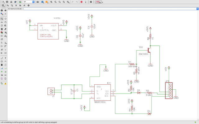
I googled it and found a lot of similar problems. The solution to this problem is to use tri-state buffer, open-collector or open-emitter circuit. Yamamoto-san, the electronics guru in our lab, adviced me to use an open-collector circuit and taught me how to use it.
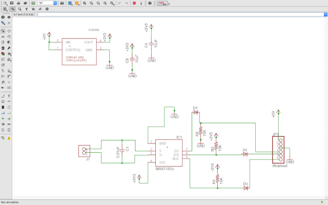
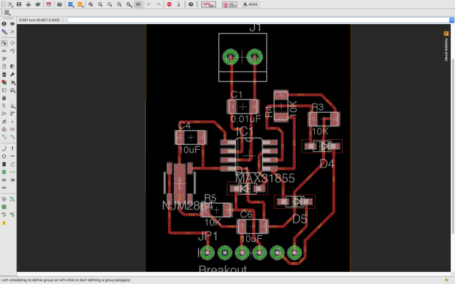
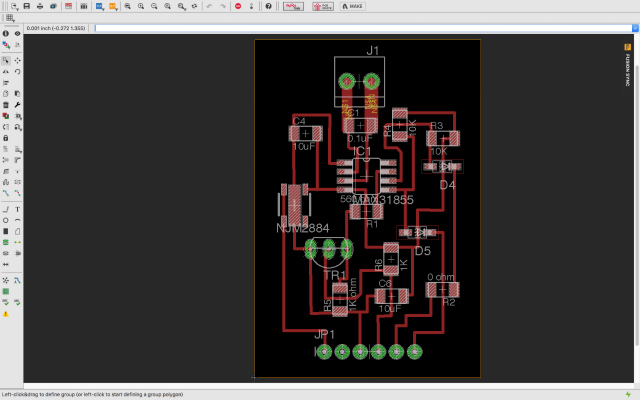
I drew an Eagle schematic of K-type thermocouple converter(MAX31855 microprocessor) circuit again with an open-collector circuit and PCB layout here.
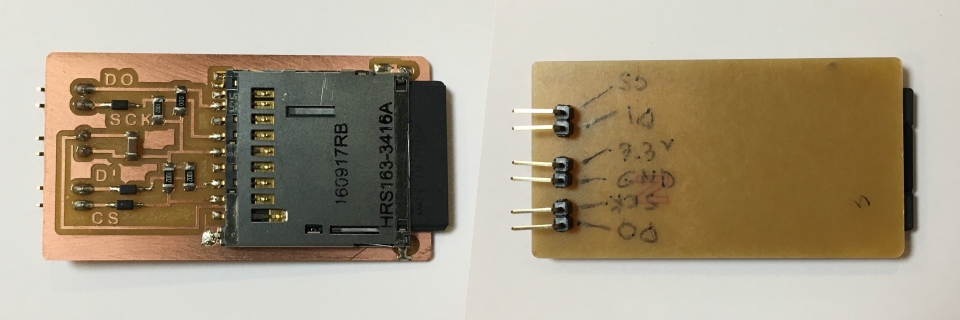
Also, I drew a schematic of an SD card module.
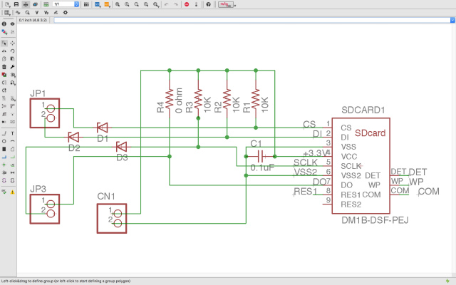
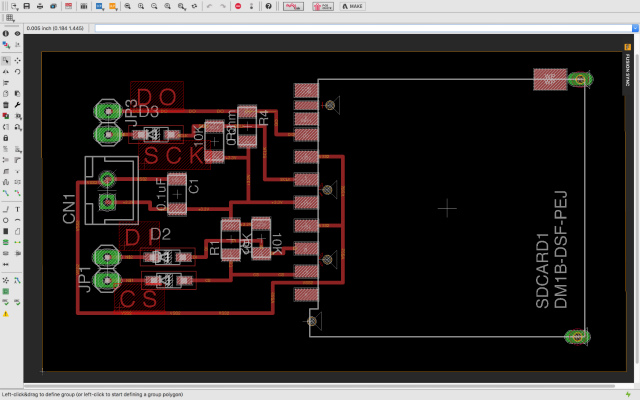
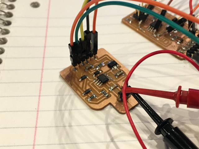
After soldering all components, I confirmed that temperature data were successfully stored in an SD card!
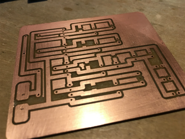
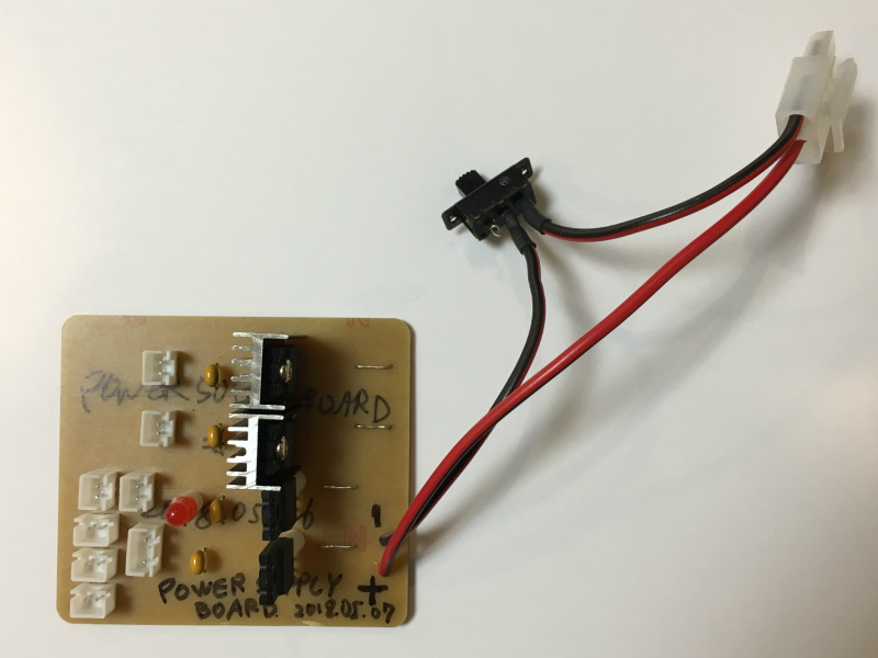
power supply board
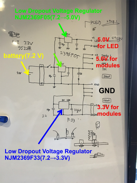
I need a battery and also 5.0 V and 3.3 V power supply from it. With the great help of Yamamoto-san, I drew a power supply board. I used four low dropout voltage regulators, three of them are 7.2V to 5.0V (for LED strips, satshakit, and others), and one is 7.2 V to 3.3 V (for an SD card module).
Here is a rough sketch I was going to draw an Eagle schematic.
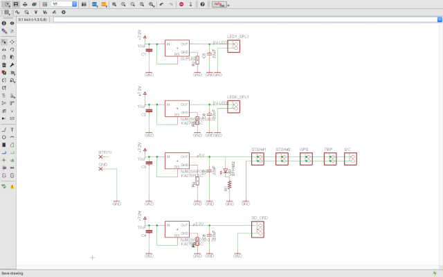
Eagle schematic
and PCB layout.
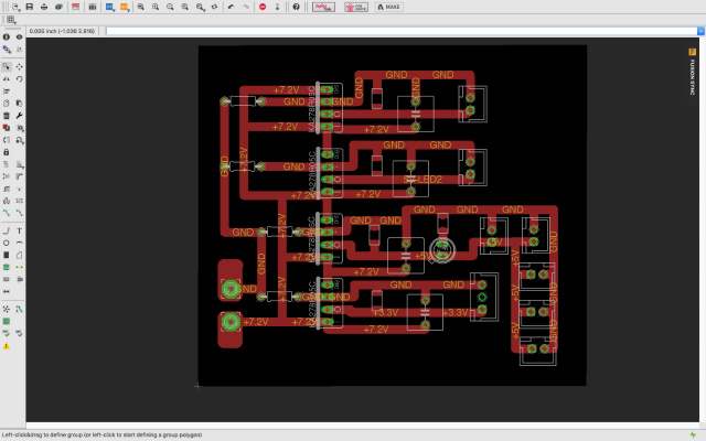
I machined a PCB.
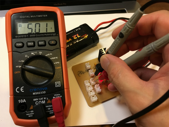
I soldered all components required. I connected the board to a battery and checked an indicator LED was on.
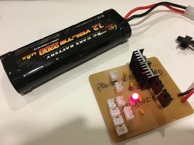
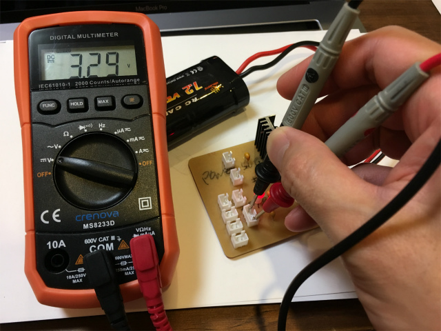
I also checked that regulators successfully convert 7.2 V to 5.0 V and 3.3 V output.
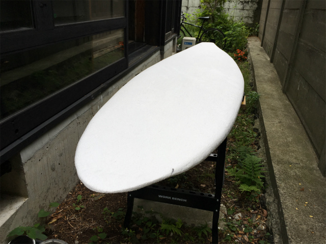
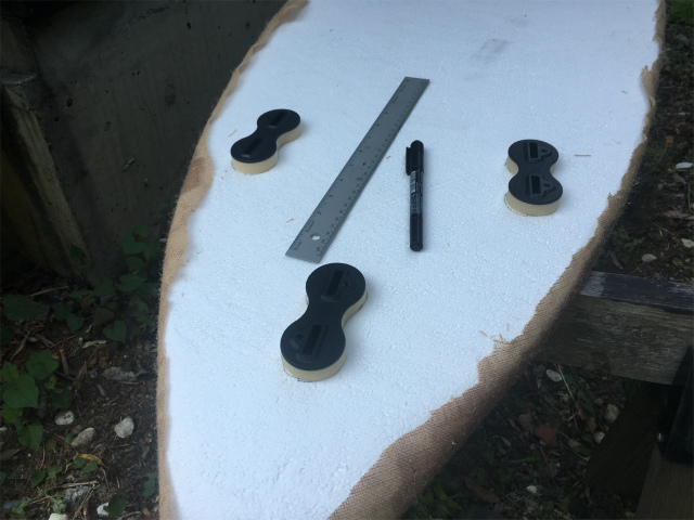
postprocessing a surfboard
Before applying fabric onto my surfboard, I sanded its surface lightly.
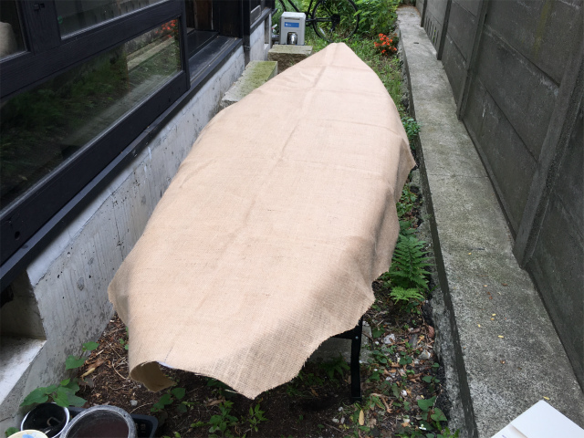
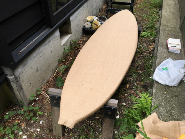
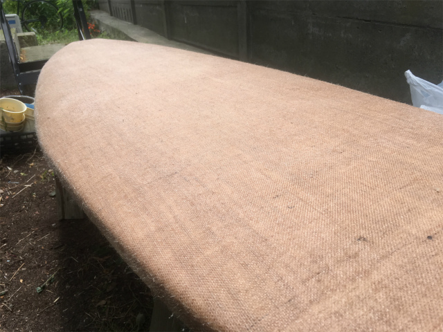
I laid Jute fabric on the top side of a surfboard. Fabric size was big enough to cover the entire surfboard surface.
I temporarily fixed the fabric with masking tapes.
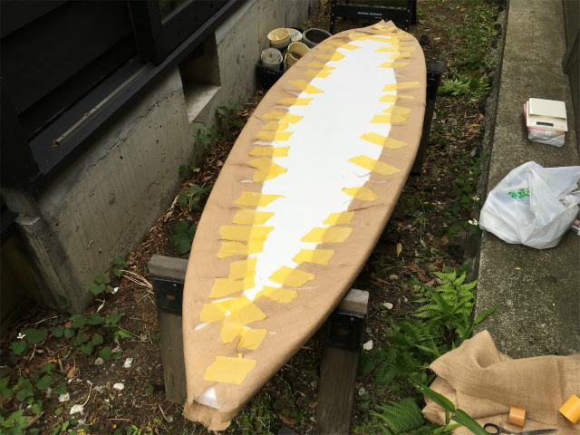
It's ready for applying a resin.
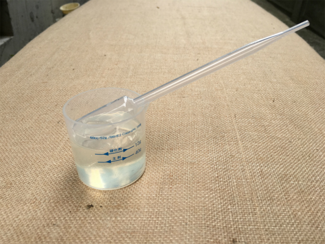
I used two-part epoxy resin, GM-6600.
I coated resin on the entire surface of a board.

After a few hours, it hardened pretty well. I left it still for days.
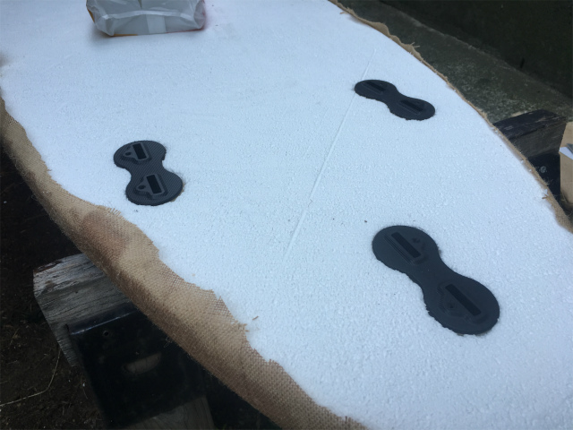
Bottom. I have to install fin boxes.
I dig a hole with an engraving knife. I poured resin into a hole and install a finbox and left for days again.
As I did to the top side, I also coated the bottom side of a surfboard.
I cut the unnecessary part of the fabric and installed fins which I made in week 10 (molding and casting) and during final development (3d-printed and 3d-printed-molding & casting ones.
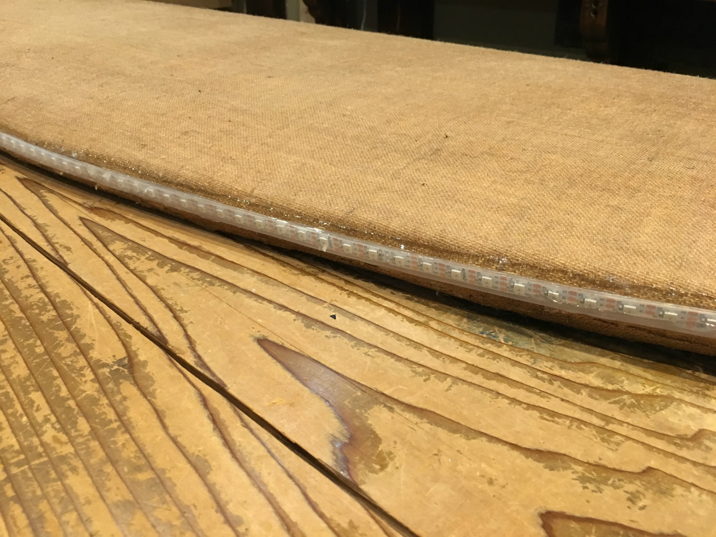
I glued LED strips on both surfboard rails with a waterproof silicone sealant.
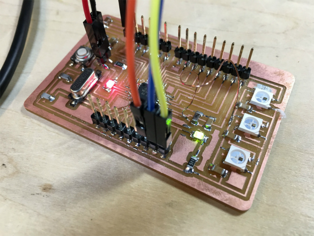
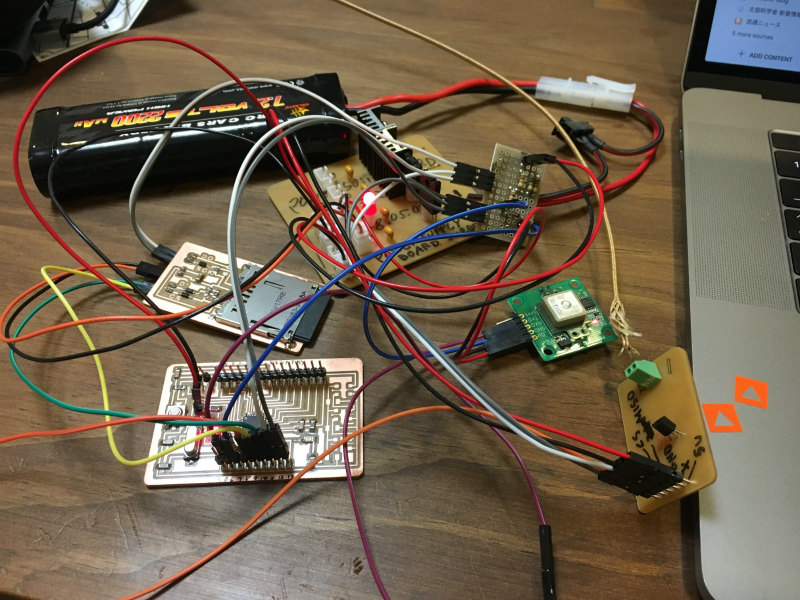
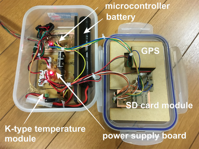
integration
microcontroller board: Junino (satshakit)
sd card module
K-type thermocouple converter module
power supply board
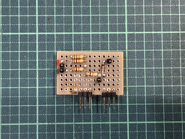
interconnection universal board for MISO and SCK, and a simple voltage divider (5.0 V to 3.3 V) for logic input of GPS module.
and integration.
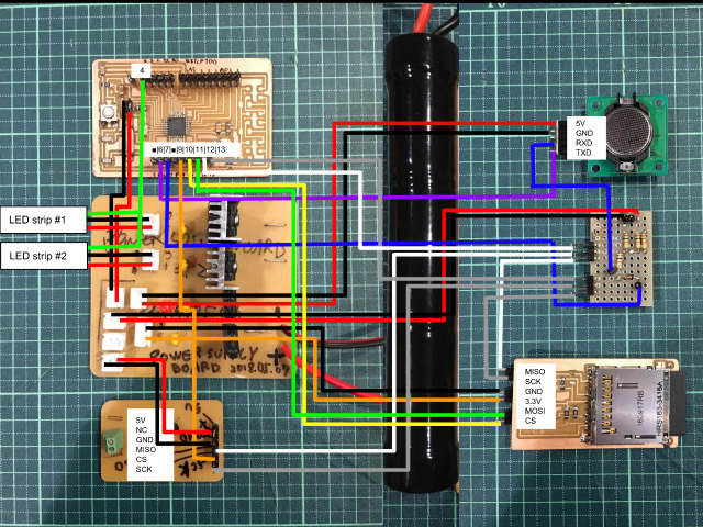
Reality...tangling wirings. I have more wires from LED strips and also have to make them waterproof. I have a long way to do...
packaging and waterproof
In an initial concept, I intended to design a waterproof enclosure for electronics. I gave up the idea because of the time management and technical difficulties and used a commercial watertight enclosure. I still have to make electrical connections waterproof between a microcontroller and LED strips on a surfboard.
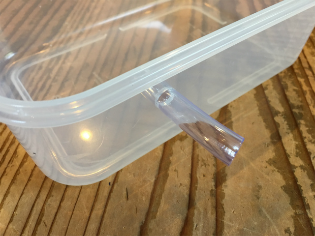
I put all wirings in a tube.
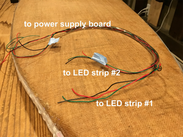
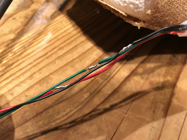
I mated the wiring and a LED strip and later covered them with a heatshrink tube.
I made a hole for a tube with a reamer.
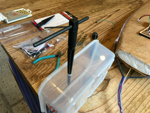
I checked the size was right.
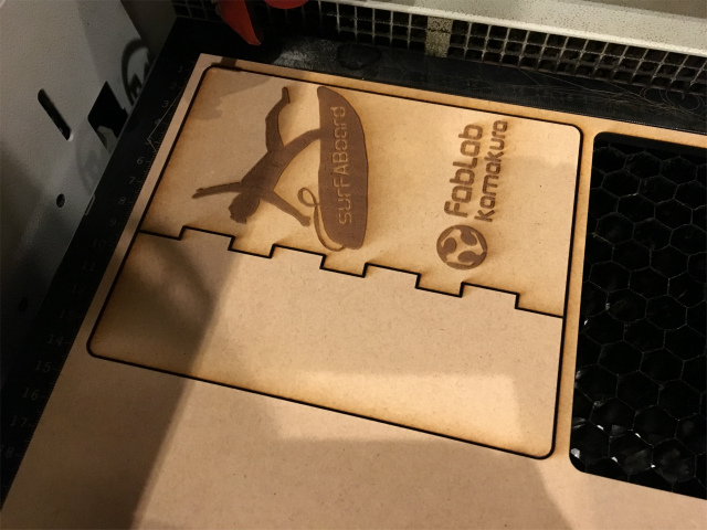
I laser-cut the MDF board for a partition in an enclosure and engraved surFABoard and Fablab Kamarkura logos.
I electronics on the partition.

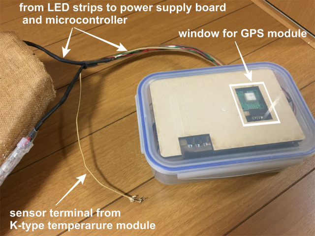
I put it in an enclosure and connect all wirings including wiring from a surfboard through a tube.
Wires between a surfboard and microcontroller board inside a tube are kept waterproofed. At the top of a watertight box, I designed a window for GPS sensors so that it can catch a GPS signal.
June
program flow
Program flow is shown as follows. In an early stage, only temperature data were stored when the GPS module didn't get a signal. I used a flag(gpsflag) to wait until the GPS module got a signal.
Once the temperature data is stored in a character array (strBuf), a function (writeSD) use the array to write the data in an SD card.
Time, day, latitude and longitude data were stored in turn in an array (gpsBuf). A sketch searches the position of the end of the array (gpsnull=0) and adds data at the end of the array.
A code for SPI reading and SD card storing is based on this sketch.
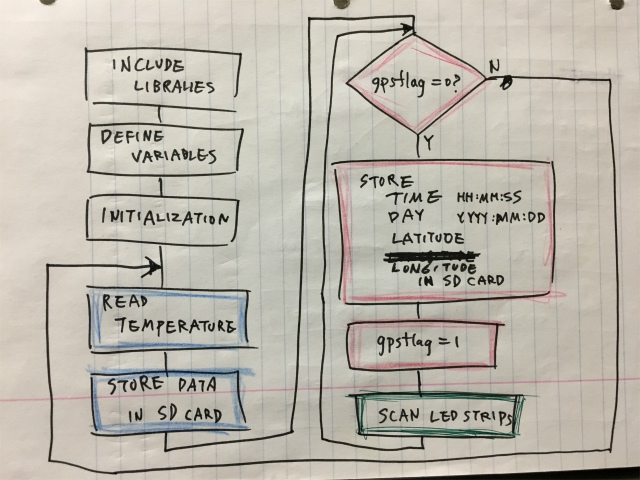
I made LED strips scan like KITT from Knight Rider. I referred a program, Neopixel-Knightrider sketch.
checking of operation
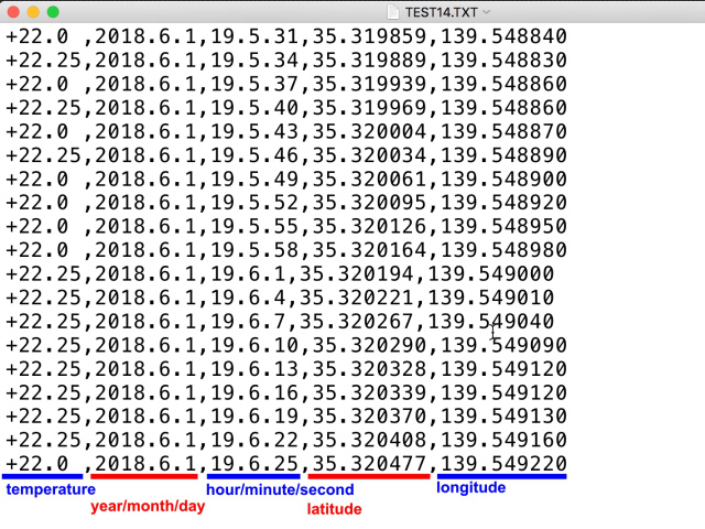
I walked around my Lab, and I confirmed that temperature and GPS location data was logged in an SD card as comma-separated values (.csv) successfully.
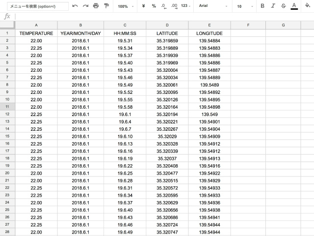
I opened the CSV file with google spreadsheet.
I uploaded GPS data (latitude and longitude) to GPSVisualizer to draw my GPS data.
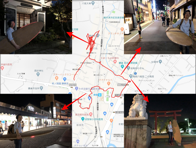
I think I've achieved my evaluation criteria for my final project.
files
K-type temperature converter module (Eagle schematic/PCB layout): archived format (.zip)
SD card module: archived format (.zip)
power supply board: archived format (.zip)
satshakit sketch: Arduino sketch (.ino)