The group is me and Solomon Kiflom from Aalto. Our plan is to make a rotary table for photogrammetry.
Figure 1. Rotary table for 3D scan. Screen dump from Autodesk Fusion 360.
Here is a video from Solomon. Video 1.
I have done my own version of the rotary table based on the origial Autodesk file form Solomon. I made some changes for the final machine.
I rejected the outer bearings from the model, and I reduced the number of the inner bearings to three.
It is possible to lift the top rotary plate from the board.
I copy the surfaces from the Fusion model and export it to Inkscape.
Then I lasercut the parts out in plexiglas.
The spurgear I draw in Fusion and export the file to a stl file and print it out in 3D.
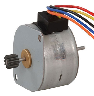
The motir was a Unipolar Stepper Motor Step 7 Volt DC-350 mA 7.5 Step Angle 680 G-CM
from Jamenco (Part no.: 2138812)
To run the stepper motor I used the uni-polar-stepper-board I made for the week 13 assignment.
Figure 2. Unipolar stepper motor used for the rotary table.
The stepper motor connection is: Orage to Power, black to PA0, yellow to PA1, red to PA2, and blue to PA3.
For clock ward rotation of the stepping motor the sequence is: (PA0, PA2), (PA0, PA3), (PA1, PA3), and (PA1, PA2).
From Fusion Model to Lasercuting
Select a surfaces
Create a sketch
Stop Sketch
Go to sketches - now there will be a new sketch.
Right click on this new sketch and save it to DXF.
Open the DXF file in Inkscape and prepare the file for laser cutting.
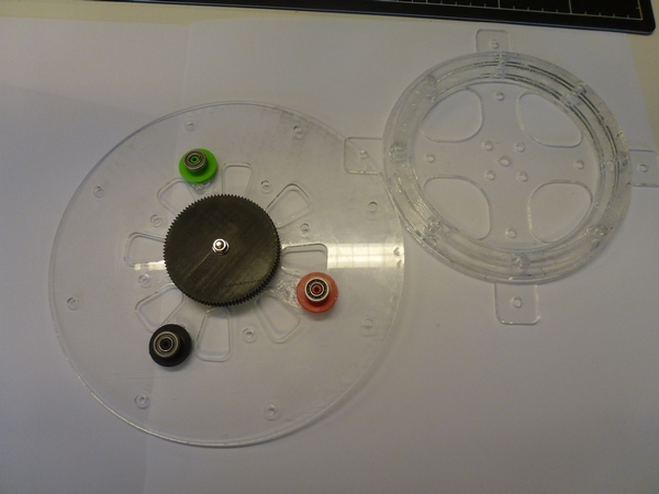
I had no bearings that fit the model from Solomon, so I made a short cut here and took 3 bearings from a fidget spinner,
and glued them to the top spinning part of the turning table.
Figure 2. Rotary table for 3D scan. My version.
For long time I struggle to run a c-code for the stepper motor, then I test the output from My Stepper board. Using a bredboard I connected 4 light diodes
(every diode was connected in serial with a 330 Ohm resistor).
Then I change the c-code to run every step slowly (0.5 seconds delay, see Video 2). Below is an example of one step function (step 1)
void step1() {
set(PORTA,PA0);
set(PORTA,PA3);
_delay_ms(timesignal);
clear(PORTA,PA0);
clear(PORTA,PA3);
_delay_ms(timedelay);
}
where:
#define timedelay 10 // after clear port
#define timesignal 500 // after set port
I found out that the Port PA0 MOSFET never turn of, mean that there probably was a shortcut to the input ground.
After re-soldering the PA0 MOSFET the light diode give a correct light pattern (Se Video below).
I program the stepper motor to turn the table 360 degrees with 5 seconds stops for every 15 degrees to take a picture (See video 3).
The c-code contain several constants for pre-run settings.
