Measure the power consumption of an output device.
Individual Assignment
Add an output device to a microcontroller board you've designed, and program it to do something.
Introduction
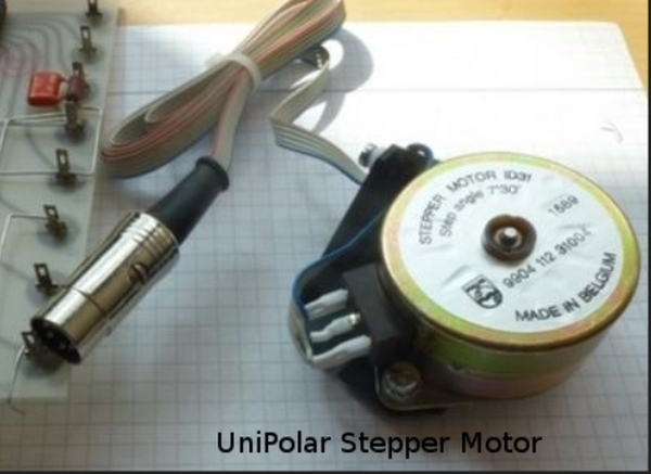
I planned to put life in an old step motor (See Figure 1)
I get some introduction on the Internet about steppe motors, especialy I notice the difference between unipolar and bipolar stepper motors.
The stepper motor which I plan to use for this week assignment has 5 connection, so I am convinced that this is a unipolar stepper motor.
I look for the production number on the Internet, and found this information:
9904-112-31004 - Stepper Motor, Unipolar, 2.8 N-cm, 175 mA, Four, 65 ohm, 100 mH.
The instrument stepper motors are high quality permanent magnet types providing a 7.5 degree step angle. The motors may be specified factory fitted with a gearhead where
increased torque and resolution are required at reduced operating speed.
Figure 1. An old Unipolar Stepper motor, from the physics laboratory on the local high school.
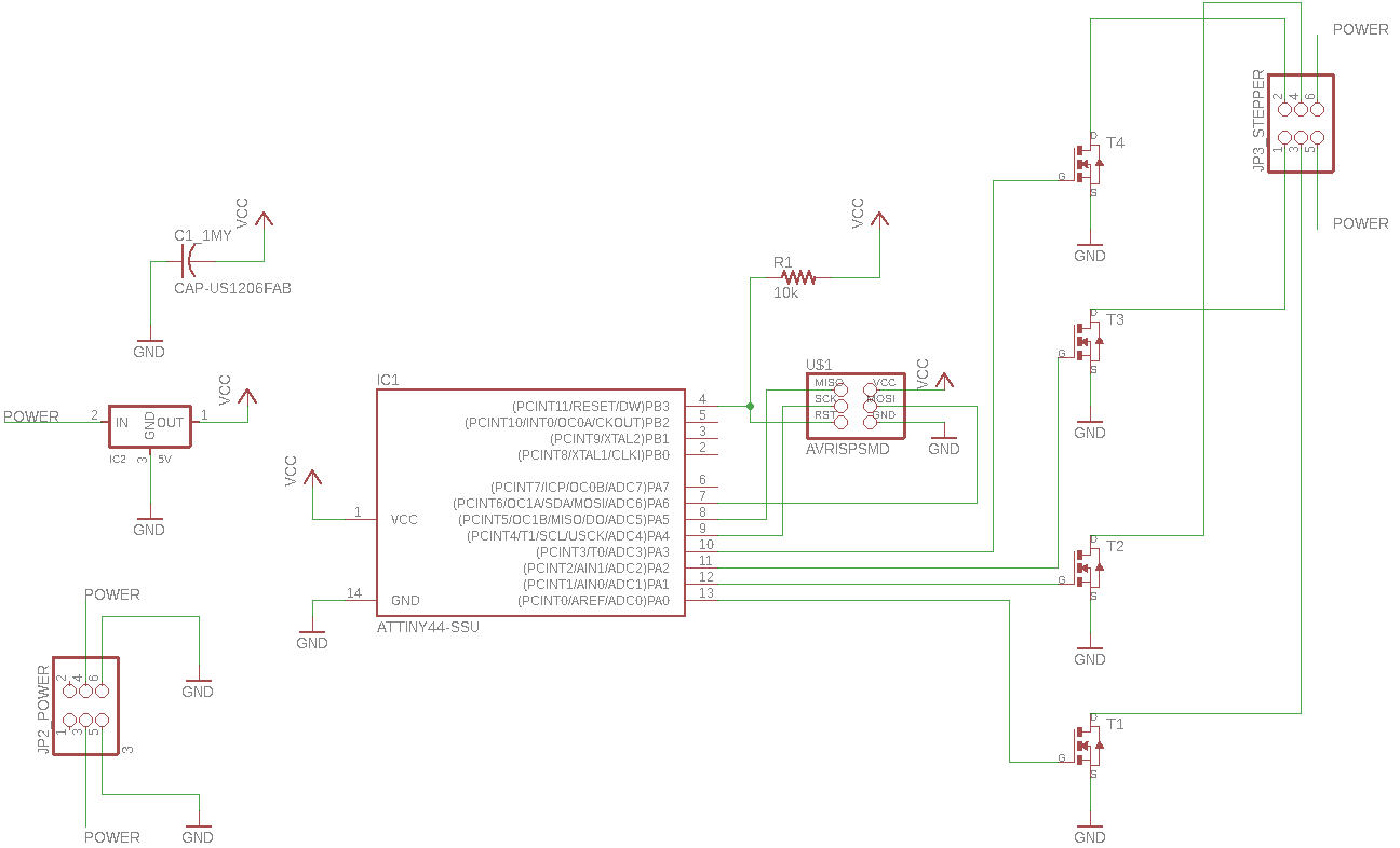
I will use EAGLE to redraw Neil's board of unipolar stepper motor - with some modification.
How to draw a board using EAGLE, is described in the week 9 assignment.
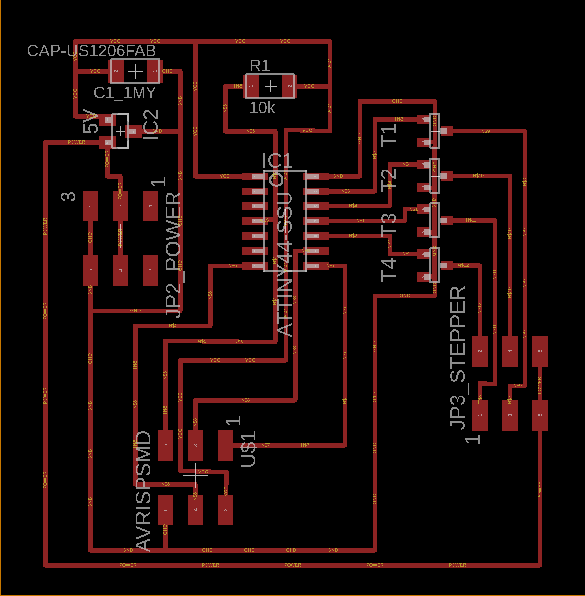
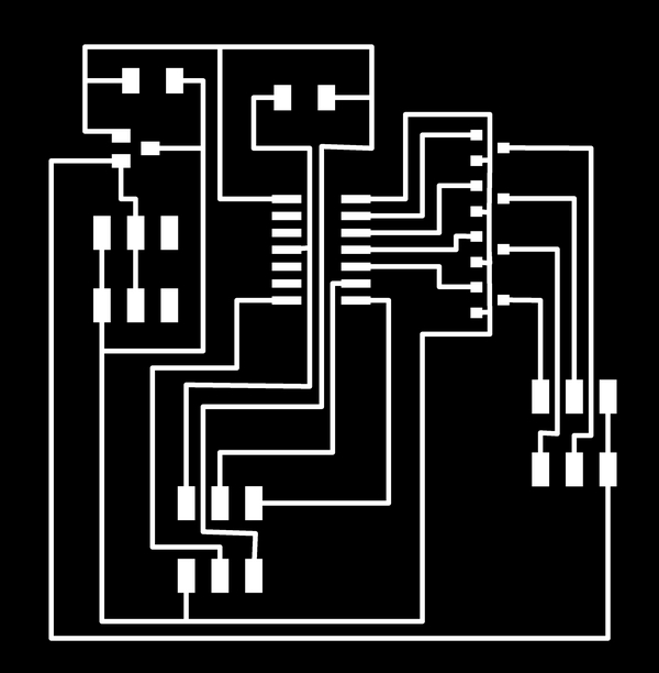
Notes: In general the wire width was set to 0.36 mm. But there was no space for this wire through the MOSFET, there I put the wire width to 0.2 mm (the max. size).
For the stepper power the wire width was set to 0.508 mm (I have no argument of this specific width, just that it is wider then normal and should take more current).
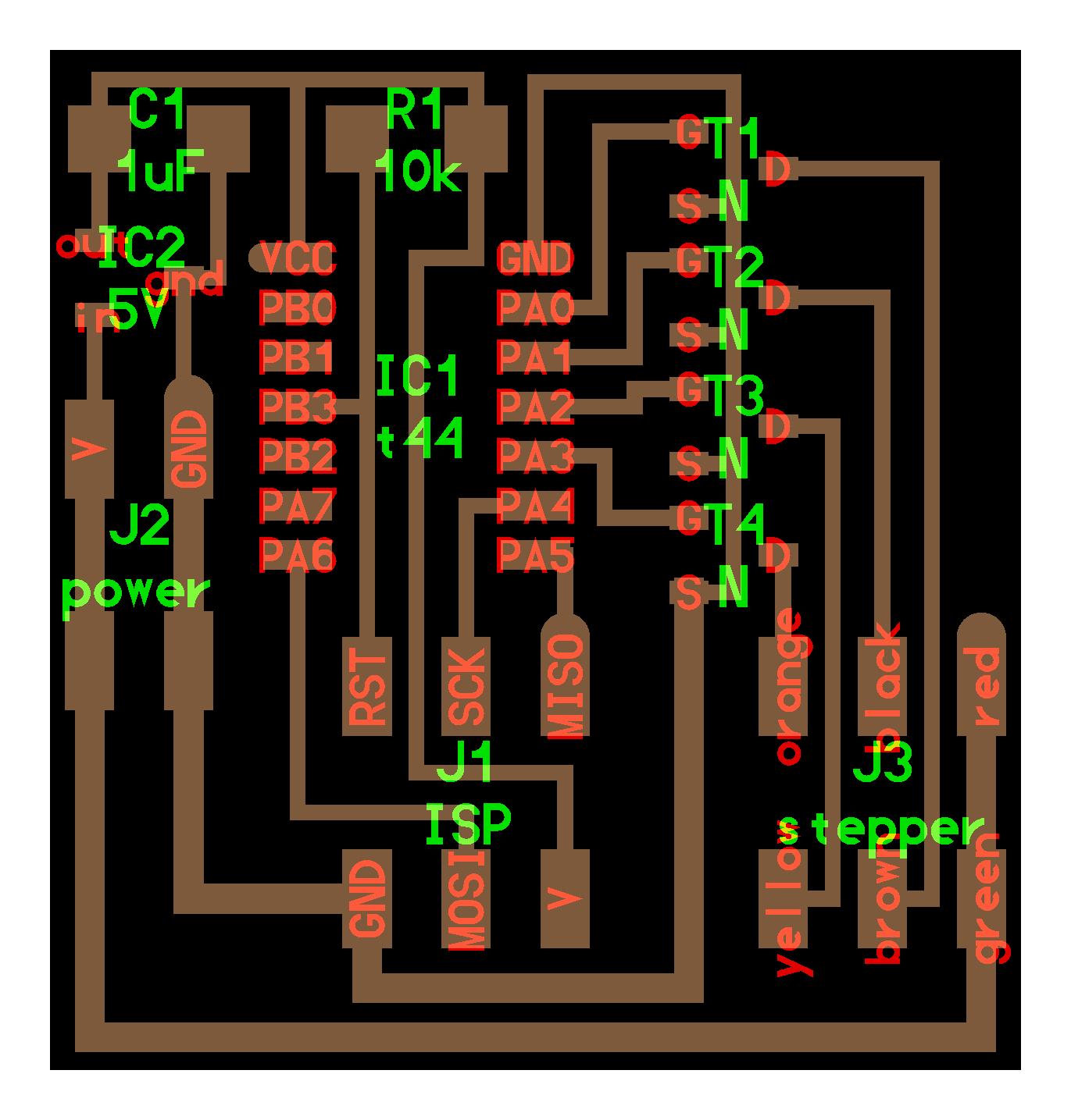
Figure 2. An EAGLE schematic to the Unipolar Stepper motor.
Note that for the J2 Power header I use a 2X3 pins header because I don't have access to any 2x2 pins header.
Figure 3. Left: A corresponding EAGLE board. Right: The output device traces.
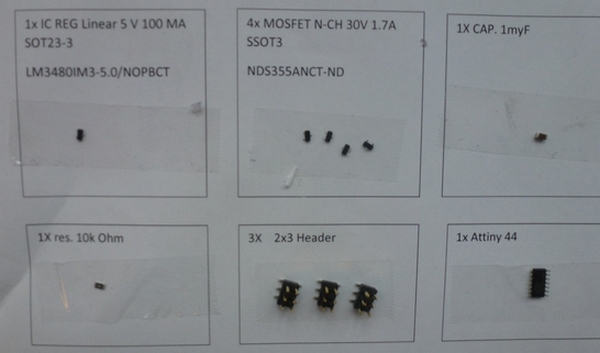
Figure 4. The component list sheet, ready for soldering.
The components list:
1x Attiny 44
1x IC REG Linear 5 V 100 mA, Digi-key nr. LM3480IM3-5.0/NOPBCT
4x MOSFET N-CH 30V 1.7A, Digi-key nr. NDS355ANCT-ND
1x CAP. 1myF
1x RES. 10k Ohm
3x (2X3) Header
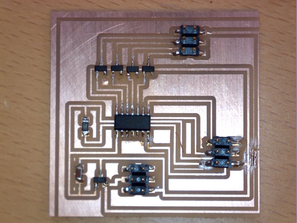
Figure 5. The uni polar stepper soldered board.
From the Fabacademy team side I downloaded the hello.stepper.44.wave c and make file.
I connect the board to the ISP and to the power supply (10 V) using the 2x3 headers and cables. The connection to the power supply goes via a breadboard.
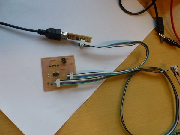
Figure 6. The board .
To produce the hex file: In Git Bash go to the project directory and write the command: make -f hello.stepper.44.wave.make
I used avrdude (In Git Bash) with the resulting .hex file from Neal to flash the board with my programmer.
The command is: make -f hello.stepper.44.wave.make program-usbtiny
or you can look into the make file and write the avrdude command: avrdude -p t44 -P usb -c usbtiny -U flash:w:hello.stepper.44.wave.c.hex
NOTE: Here I struggle for hours with an error: **** missing separator. Stop
The solution was to change the spaces to tabs in front of the avr. commands, and the avrdude was done.
Now I disconnect the board from the ISP, and connect the stepper motor also via a breadboard and some old DIN-5 av connection.
See below how to do the stepper motor connection.
Figure 7. The board .
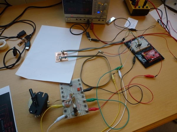
Figure 8. The final setup.
At the end I started the power supply (10 v), and the stepper motor start to wave.
NOTE: Using a voltmeter I measured the output voltage of the regulator. I shows an constant output value of 5 V no matter the power supply voltage (5-10 volt)
The Power voltage was measured to 9.85 V and the main current was 11.4 mA - (Note for this stepper motor the max current is 175 mA see description of the 9904-112-31004 stepper motor).
The voltage over the 4 coil in the stepper motor was around 9.50 V.
Video of the result.
I found that there is something wrong with the behavior of the stepper motor, I have not figured it out yet. [Postlude: In week 16 I found an error of the stepper board.]
5 Wires Unipolar Stepper Motor Connection
First we need to identify the wires. There's no data-sheet, so we need to do
some tests to identify the wires.
A good idea is to connect the stepper motor to a breadboard.
There are 4 coil ends wires and 1 center tap wire(See Figure 9.)
Figure 9. The wires of Unipolar stepper motors.
To identify the center tap, we can measure the resistance between every pair of wires, and put the values in a table (See Table 1).
Table 1. The resistance [Ohm] between two wires in the unipolar stepper motor.
A
B
C
D
E
A
0
68
71
66
67
B
68
0
136
132
132
C
71
136
0
135
135
D
66
132
135
0
131
E
67
132
135
131
0
Table 1 shows two levels of resistance (around 70 Ohm and around 135 Ohm). There is only one coil between the center tap wire and the coil end wires
but between two coil end wires there are two coils which give double resistance. So, from Table 1 we can identify the center tap wire as wire A.
Now connect wire A to "+" (10 V).
Named one of the other wires nr. 4., and connect it to "-" (0 V). (NOTE: put a resistance somewhere in the circuit to prevent short circuit
After turn connect the other wires to "-", while you observe the behavior of the stepper motor. Name the wires according this schedule:
Name 1: If the stepper motor goes counter clock wise.
Name 2: If nothing happens.
Name 3: If the stepper motor goes clock wise.
Now I have make my identification of the wires 1,2,3, and 4. Note that the identification is not absolute, but is ordered circular (1,2,3,4 or 2,3,4,1 or 3,4,1,2 or 4,1,2,3).
Stepping clock-wise the sequence when the end coil wires should be connect to zero (or "-") is:
1 and 3
1 and 4
2 and 4
2 and 3.
Here is a good link to YouTube how to identify the wires.

