This is the Sixth week assignment for the Fab Academy 2018..
Electronics design
There are many types of circuits that you can design on a PCB like analog, digital, RF and the PCB layout may make-or-break the performance and working of the circuit. Your circuit may work as a prototype on a breadboard, but it might not work on a PCB. PCB designing is an art. While it may come naturally to some, it can be daunting even for experienced circuit designers. And this is why many companies hire PCB experts! You can find PCBs everywhere, all around you inside computers, phones, power supply, watches, thermostats, cameras, automobiles, traffic lights, microwave oven, refrigerator and they are increasing which means PCB designers are in demand now, and will remain so for a while! As a matter of fact, PCB designing is a creative and individual learning process. We can only teach the basics, but the technique will mature once you start working on more and more projects. To become an expert in PCB design, it takes a great deal of talent and knowledge to place components as close as possible without compromising the performance of the circuit
introduction to eagle softwareTwo weeks ago, we produced our own PCB board, using the already premade design. This week, we are going to design our own board.
Tasks:
- Select and use software for circuit board design
- Demonstrate workflows used in circuit board design
- Redraw the echo hello-world board, add (at least) a button and LED (with current-limiting resistor), check the design rules, and make it

Ohm's law is the most important law to understand and memorize so to know which components to use for each board. Thiswebsite is very helpful and can assist you in calculation.

This week we'll be using Atmel Board which is the same one we have used on the week of Electronics Production which was the Attiny44. To understand well where I should be connecting the components; I checked theAttiny44 Data Sheet.

We have added the Fab Library to the Eagle software so to choose the components we are going to use. These are the components I'll be using.
- Attiny44
- LED *2
- Button*1
- Crystal*1
- Resistors*2


I have used these labels to avoid confusion if I have used cables all over.

schematics for my board.


It is required from us to use a button and LED I have added another functions which are if your press the reset button and when connected to the power the LED will blink.

To make the board be able to communicate with the PC I have added FTDI SMD-Header which will connect its cable to my PC serially.

The final issue is the connection between this board the ISP we have made earlier for programming our new board.

I went to file then pressed switch to board.

Once you press switch to board the components will be shown on the side which look like a spider net but in reality it is not complicated as it look like.

I have increased the Grid resolution through view menu and pressing on Grid then I have changed values to 0.01which help me to be more precise while drawing the route lines.

To be clear I have put the drawing against the Schematic so to be able to distinguish the components before and after.

For easier view I went visible layers first chose none then I chose top as only shows the traces.

I have added my initials to the board which also can be read by the milling machine.

Before exporting my board as an image to start the fabrication process, I had to make sure everything is correct. To do that I used the command DRC which checks the board against a set of rules to make sure the board meets those rules. I downloaded the Fab Academy Design Rules and loaded it to check my design against it.

I saved it as an image so I can export the file as png extension.

From what appear in window I increase the resolution to 1500 dpi also I have checked the Monochrome and selected for the area full.
Fabmodules
Milling and Soldering

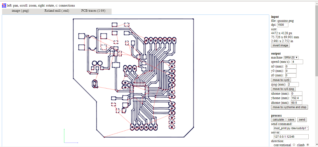
I have exported the image file to Fabmodules so to make milling on Roland SRM20 machine.
On the right side you get a setting bar to choose type of the machine you are going to use.
- Machine - SRM-20
- x0(mm) - 0
- y0(mm) - 0
- z0(mm) - 0
- zjopg - 12
- Speed - 4

This is the outcut for the board. To repeat the same Z origin procedure but before we have to change the end mill to use the 1/32 end mill.and the cut depth 1.75mm. After zeroing the Z (only the Z)click CUT again in the control panel but now choose your Outcut/Holes files and click Output.

This is after milling and components are ready on the side.

Here the board after soldering and adding the components and is ready to be uploaded.
Programming
Our mission is to program the board. I chose to program it using Arduino as ISP. The first step is to patch the arduino so to recognize the Atmel Attiny 44 microcontroller. I followed the steps in the tutorial bellow. I connected my arduino and uploaded the Arduino Isp program. This took a lot of time as I have faced some issues but I kept the effort to find ways to solve all issues and uploaded it. .


First I have connected my PCB then I have connected my board with the Arduino.

The first step to program the board was to patch the ATtiny 44 with Arduino ide. I opened the preferenes dialog on Arduino IDE, found the "Additional Boards Manager URLs" and pasted this URL into the field and pressed ok: "https://raw.githubusercontent.com/damellis/attiny/ide-1.6.x-boards-manager/package_damellis_attiny_index.json". Then, I opened the boards manager under board on the tools menu. After I opened it, when I scrolled down to the list I saw the entry of ATtiny, I pressed on it and installed it.

Went to tools I chose type of board as Attiny24/44/84

From tools and chose for Processor Attiny44.

From tools I chose for Clock External 20 MHz

From tools I chose for Programmer Arduino as ISP.


Problem!!
Then I pressed burn bootloader but unfortunately it kept giving a message that error with connection. I have tested all connection to make sure that it is all connected and there are no short circuit then tried again but still the same error message so I checked the soldering again and tested each single wire and nothing faulty but still getting the same error message. So I have decided to try from another laptop as it might be the problem from my laptop also it didn't work. I made another milling for the board so to be ready just in case. Last solution which worked I desoldered the microcontroller and inserted new one' I think the issue could be that I kept the iron for longer than it should be so it was burnt. Even though it took long time but it was good learning experience.

From Library I went to blink example and I uploaded to Pin 7 so to make blinking.
>
This is my final board when connected to the power the LED will blink and another LED when the reset button is pressed it will light up. Smile and blink back to it (;
Download my schematicsDownload my board
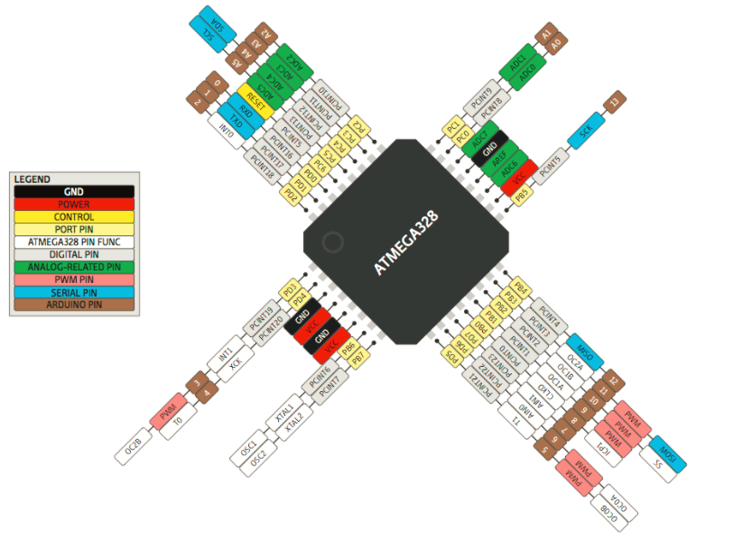
I decided to make another board using ATMEGA328P-AU to be my own Arduino.
These are the components I'll be using.
- ATMEGA328P
- -SMD-5X3MM
- 6MM_SWITCH
- LED
- Resistor(1*10k,1*499)
- Capacitor(2 * 22pf, 1*10uf)
- pinhead
- Voltage regulator
- PJ-002AH-SMT
- slide switch
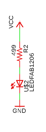
The above schematics is for an LED connected between the vcc and the gnd, this is to have the LED light up when the board is powered on.
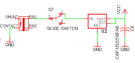
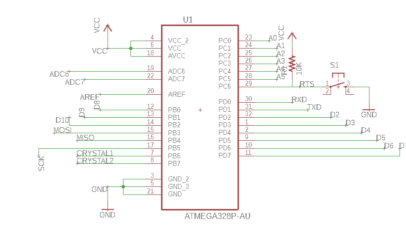
I decided to add a power jack to this board and have it powered by a 9V battery. To do that I added a power jack and slide switch to turn it on or off and of course I have to add a voltage regulater to lower the voltage from 9V to 5V so I wouldn't burn all the other components.
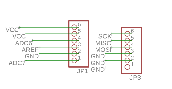
In the first attiny board, I made the mistake of not having enough VCC and GND pins. So I added more pin headers with VCC and GND connection to them.
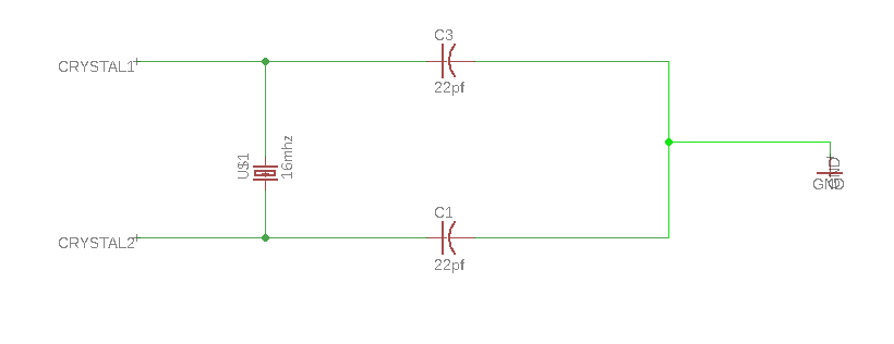
The above image shows the schematics for the 16MHz crystal that will be connected to the atemga.
The other components are connected the same as in the attiny board.
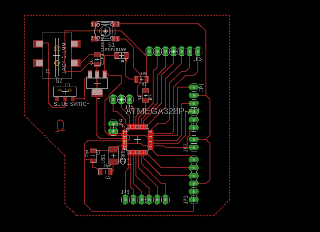
Next, I imported the design as an image, uploaded it to the fab modules and set the settings.
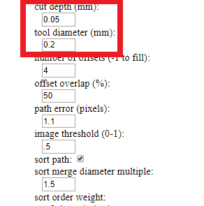
The main difference is the tool diameter that was set to 0.2mm because the atmega328P chip cannot be milled with the 0.4mm diameter.

You can see my own Arduino board above, soldered and ready to use!
Problems
I have made a small error in the design, I have set the power jack in the opposite direction and it will be so hard for me to solder it so I will fix that in my next board.
I faced another `lem during milling which is that there was a slight miss-alignment and when I cropped the image to re-mill the shiny traces, it cut the board in half! I checked all the connections using multimeter it was all fine. So I added a zero ohm resistor to reconnect the grounds.
Download my boardDownload my board
