This is a fifth week assignment for the Fab Academy 2018..
3D scanning and printing
introduction
Every 3D print starts as a digital 3D design file like a blueprint for a physical object. Trying to print without a design file is like trying to print a document on a sheet of paper without a text file. This design file is sliced into thin layers which is then sent to the 3D printer.From here on the printing process varies by technology, starting from desktop printers that melt a plastic material and lay it down onto a print platform to large industrial machines that use a laser to selectively melt metal powder at high temperatures. The printing can take hours to complete depending on the size, and the printed objects are often post-processed to reach the desired finish.
Available materials also vary by printer type, ranging from plastics to rubber, sandstone, metals and alloys - with more and more materials appearing on the market every year.
The 3D printing is developing and expanding very fast every once and again there is a new technology introduced. Now we can see that concrete 3D printing is out for building houses some restaurants started offering 3D printed food it's widely used for medical as well for printing parts also there is an excited 3D printing project by MIT using glass.
project with MSF in FABLAB IRBID
For the years I have spent working with FDM & SLA technology of 3D printing one of the best projects I have worked with is working with MSF making prosthetics for refugees in Jordan.
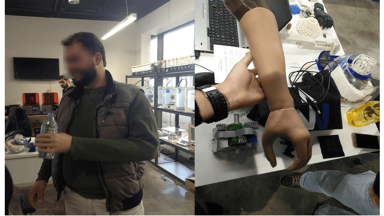
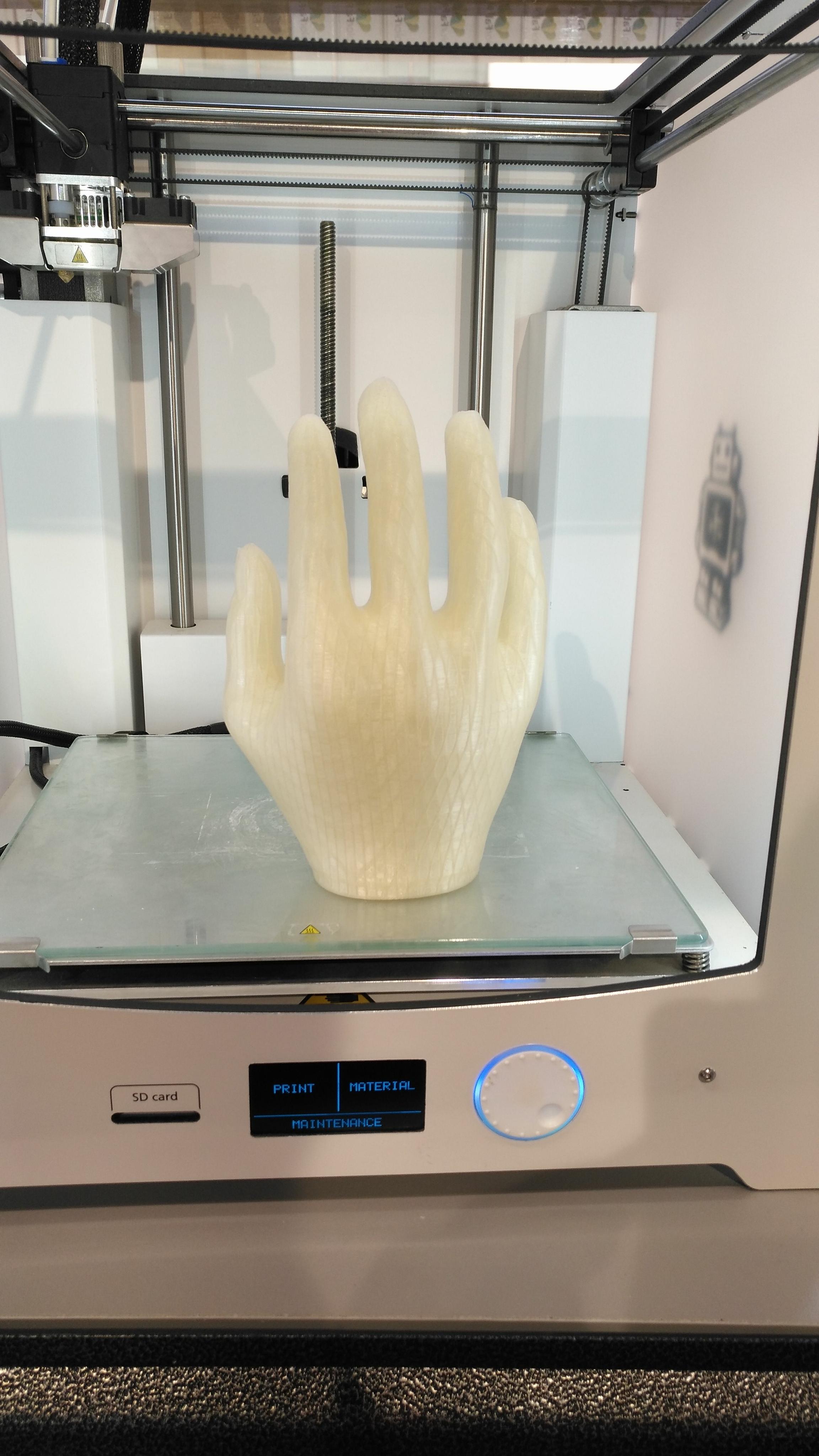
The above is a photo of one of the project with MSF.
the Filament we have used is natural PLA and TPU 90 for the
The 3D printing prosess

1.Producing a 3D file
There are more than one way to produce a file. one is to use a 3D scanner to scan an object to give you 3D model there are many types of scanners which varies in resolution another one which is the most common method for producing a digital model is Computer Aided design (CAD). The third one is through the open source community as there are many open source websites which you load from different designs. one of the famous websites in this regards is Thingiverse.
2.STL creation and file manipulation
In order to 3D print a part, a CAD model must be converted into a format that a 3D printer is able to interpret. The extension must be STL or OBJ files (The OBJ files used for the printers with full colors). After that it must be converted to G code as it is the language understood by the machine. The most famous slicer is CURA also another one is simplify3D which can you control more but it is not an open source.
3.Printing
There are many 3D printing technologies. at our Lab we have FDM from Ultimaker. we have most versions of ulitmaker and witbox-2 which I use the witbox-2 mostly for flexible materials like TPU90 & 95. also we have SLA printer from Formlabs.2 which uses different types of resins.
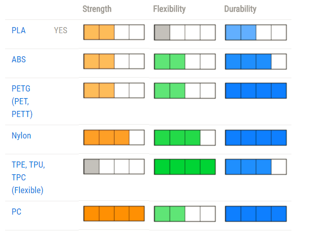
There are more than 450 materials for 3D printing' The most commonly used materials as shown in the schedule.

Now I ll start 3D printing for my final project which was designed during the design week. the part I'll be printing is the Funnel.
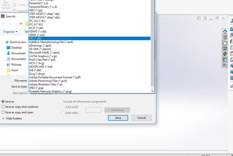
save it as STL TO GO TO CURA
Cura slices 3D models. It translates the 3D STL, OBJ or 3MF file into a format that the printer can understand. Fused filament fabrication (FFF) 3D printers print one layer upon another to build up the 3D object. Cura 3D takes the 3D model and works out how those layers are placed on the print bed and creates a set of instructions for the printer to follow layer on layer.
Cura generates instructions for your 3D printer. They are called G-Code, a text document that ends with the file extension .gcode. Open the file and you ll actually be able to read through quite a bit of the code and understand what it's telling the printer to do.
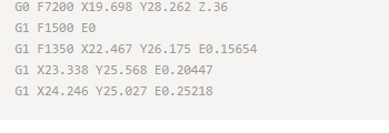
Here's a small snippet
As you become more adept at 3D printing you can go into this code and adjust fan speeds, layer heights and hot-end temperatures at different points. This can be handy when you need to troubleshoot some 3D print problems.
As every printer has a different setup, print area. build plate and nozzle size. the Cura slicing software needs to know these hardware details in a printer profile. Once it has the required details, you can then specify settings like layer height and thickness. Based on the vital stats of the printer and your settings, Cura will calculate the path the printhead needs to take in order to print your model and produce a list of instructions for the printer. These instructions are saved in that G.Code file.
The G.Code can then be saved to an SD card or sent to the printer over wireless or cable depending on the printer directly from Cura.
There are many 3D slicing programs available on the market. Cura 3D is just one of many. But over the years the continuous development and open source philosophy made this 3D slicer the gold standard. There are only a handful of 3D printers which aren't supported by Cura and if so you can even add the printer yoursel
cura settings
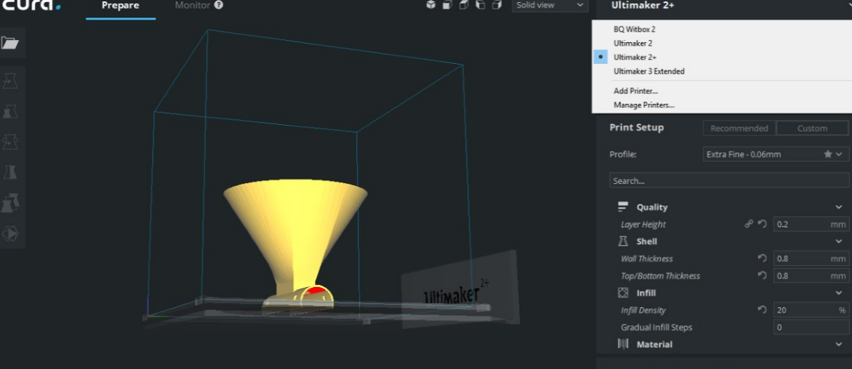
I dropped my STL file and have to choose type of machine to be used and I have chosen Ultimaker 2+. also from the list you chose type of material to be used and I have chosen PLA some settings change by default according to the material chosen like the speed, temperature and cooling. You must make sure to choose the same material which is in the machine.

Here we have different diameters for the nozzle what is good about Ultimaker 2+ is that you can change the nozzle to be like a screw easily I have chosen 0.4 mm which is most chosen diameter. The lower the nozzle diameter is it gives more accuracy but the timing will increase.
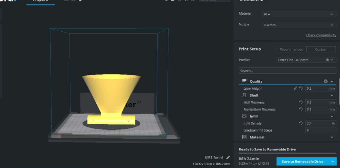
The layer height is connected directly to the quality of print the lowest gives best printing and layers can't be visible in the final print also the lowest height increase time of printing. Timing is changed according to the parameters you choose which you can see at the bottom. I put the layer height as 0.2 mm because it give medium quality as it is a trial print.
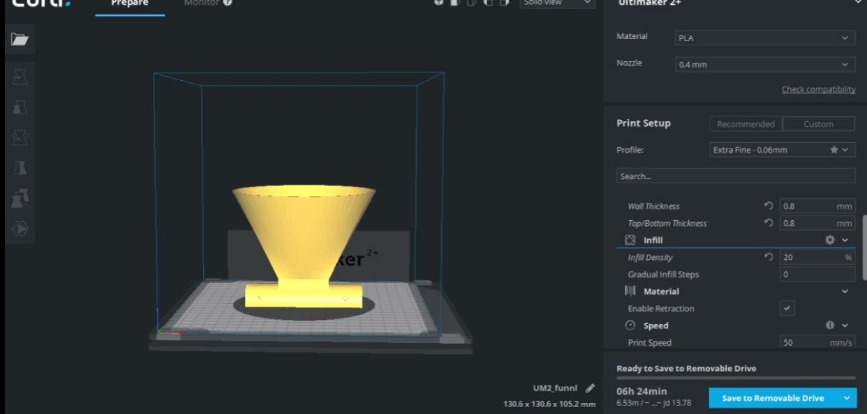
For the shell I have entered the wall thickness and bottom thickness as 0.8 mm also I have chosen 20% infill to save materials also as I wanted the print to be not that solid.
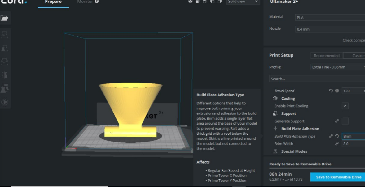
I have added a brim as it gives like a shield at the bottom of the print which makes stable and when removing the print you won't touch the print directly.
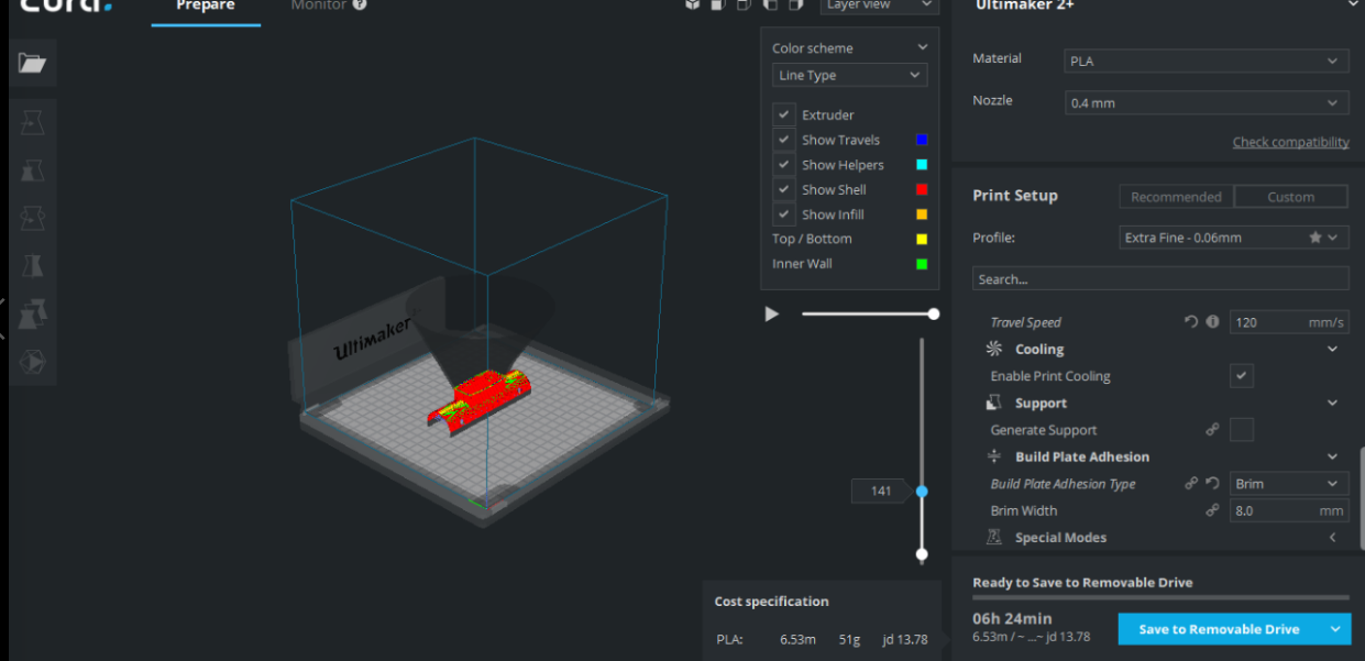
Any changes in parameter you can see from the layer view how the print will look like. Also the colors show the settings.
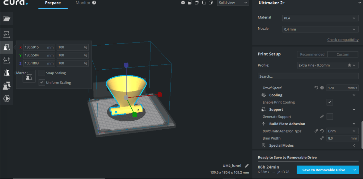
From the bar on the left you can scale, rotate, mirror and move. So as it is ready I saved it on SD card and inserted it in the Ultimaker.
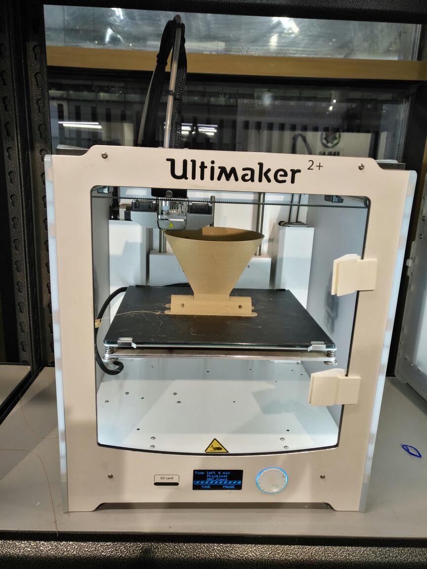
Here is the final print of the funnel. I have printed it woodfill filament as I find interesting as it gives you the wood feeling, but of course it is not a real wood; It is 80% PLA infused and 20% wood fiber.
i have used is a Ultimaker 2+
I have made the drawing for the extension between the lead screw and stepper motor on SOLIDWORKS.

I started with the circle and made an extrude for it.
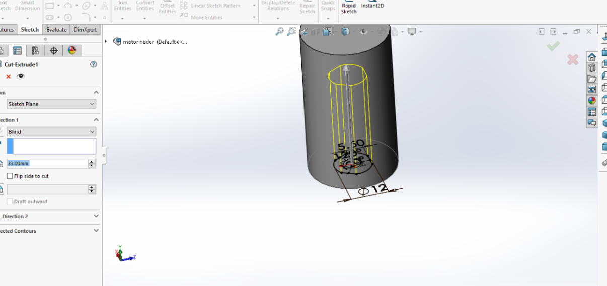
Here I have faced some difficulties on how to make an opening for the lead screw as it is Delta so I took the dimensions and drew the circle and dropped lines from one side then I have made trimming for the lines I don't need.
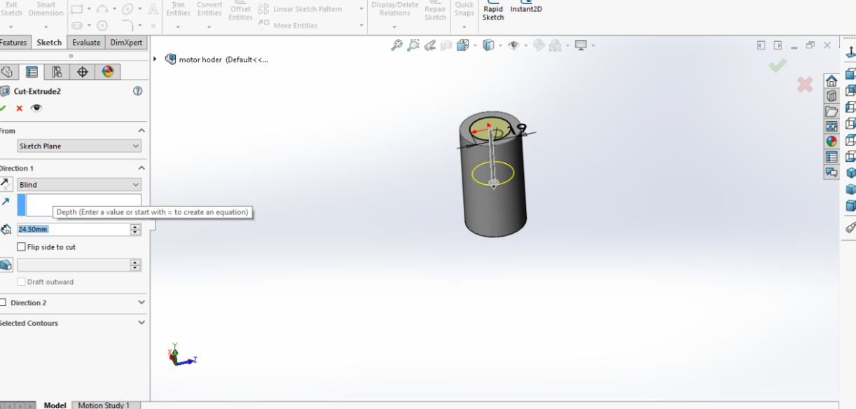
I drew another circle with the dimensions shown on the photo and made cut extrude; this will be the entry point for the stepper motor.
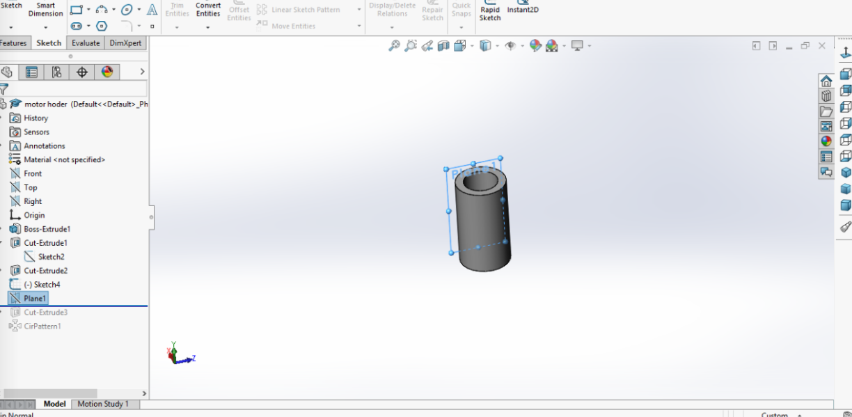
I have made a new plane as you can't draw on any surface which is not flat.
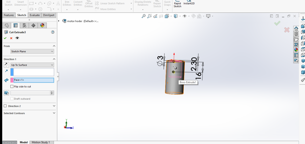
I have made holes for the screws and to have it on both sides I made extrude cut through all.
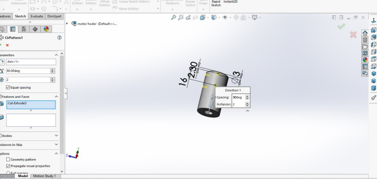
It is parametric so any change on any size it will change all.
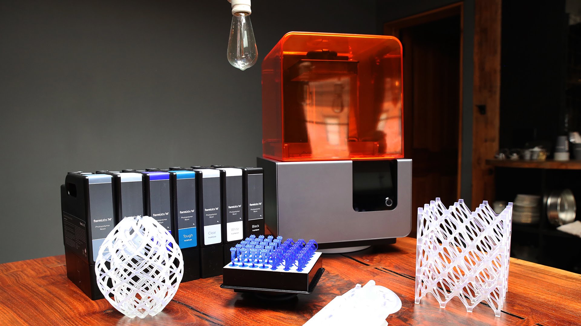
Light Processing (DLP) create 3D printed objects from a liquid (photopolymer) resin by using a light source to solidify the liquid material.
To create a 3D printed object, a build platform is submerged into a translucent tank filled with liquid resin. Once the build platform is submerged, a light located inside the machine maps each layer of the object through the bottom of the tank, thus solidifying the material. After the layer has been mapped and solidified by the light source, the platform lifts up and lets a new layer of resin flow beneath the object once again. This process is repeated layer by layer until the desired object has been completed. There are two common methods today differentiated by the light source: SLA uses a laser, whereas DLP employs a projector.

SLA & DLP 3D printers produce highly accurate parts with smooth surface finishes and are commonly used for highly detailed sculptures, jewelry molds, and prototypes. Because of their relatively small size, they are not recommended for printing large objects.
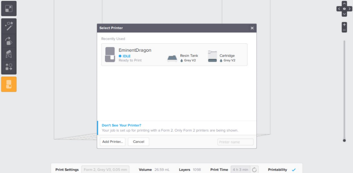
I have downloaded the slicer for Formalabs. I have dropped the file as STL file then I have chosen type of resin to be used which is gray V2 also I have chosen the printer & layer height. I went with medium quality of 0.05 mm; also with this slicer timing depends on the material and layer height.
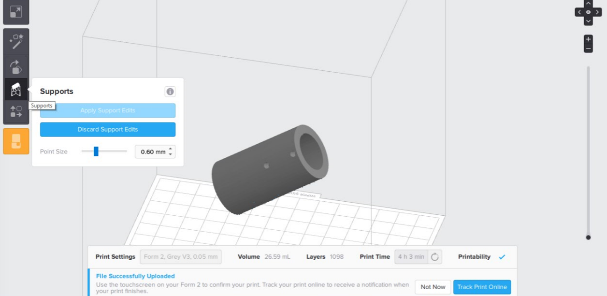
The Formlab doesn't print without support and here more details.
S
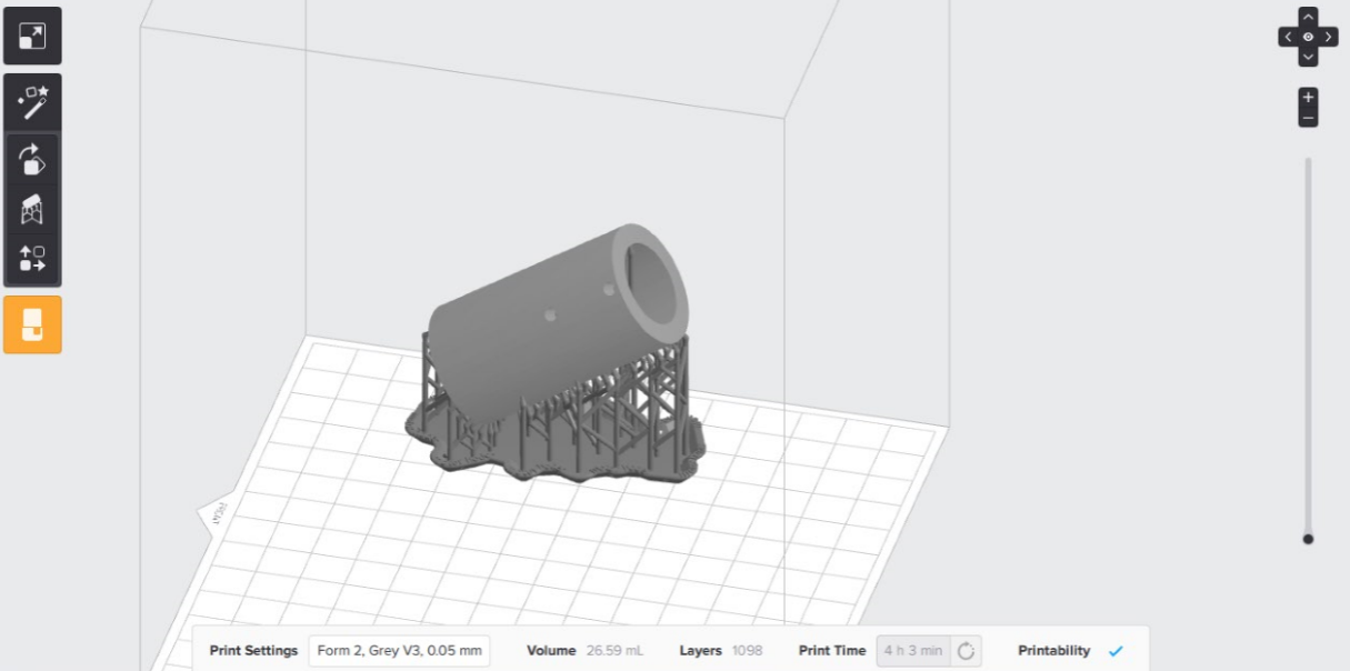
I have chosen the support. On the left side there is an icon like a magic stick which gives the best support and position. I recommend changing place of the print after each print as the tank after using 2 liters it expires.
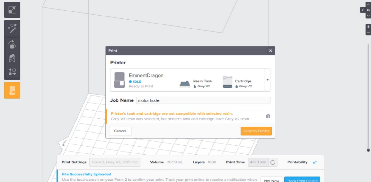
I have pressed the origin icon with a printer image to make sure that all the settings are right then you send to the printer. There are two ways to send the file: Through WIFI or through USB cable.
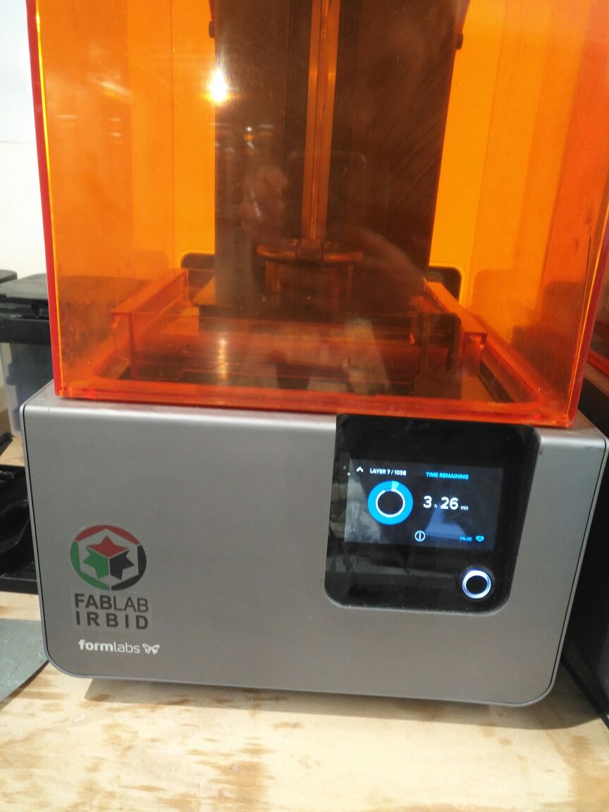
The screen gives you how many layers are done and the timing.
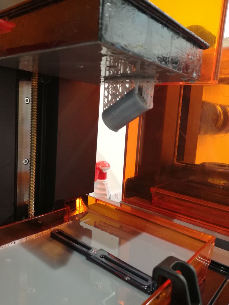
After it is done.
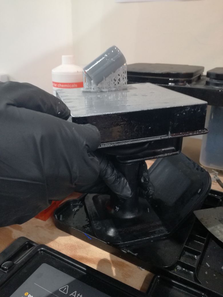
Will start the post processing so you remove it from the bed with a special tool and soak it in Alcohol for few minutes and here are more details for the finishing process.
- Remove the build platform
- Put the build platform on the jig
- Use the removal tool to remove each part
- Agitate part in IPA
- Soak parts in IPA
- Repeat with a second rinse
,- Post-cure, as needed
- Remove the supports
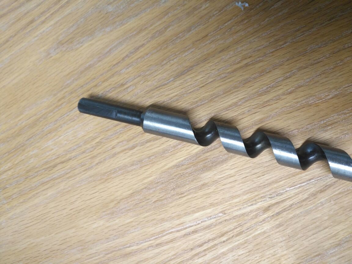
which I bought from the local market This lead screw and will try to make a similar one in our Lab in the coming weeks.
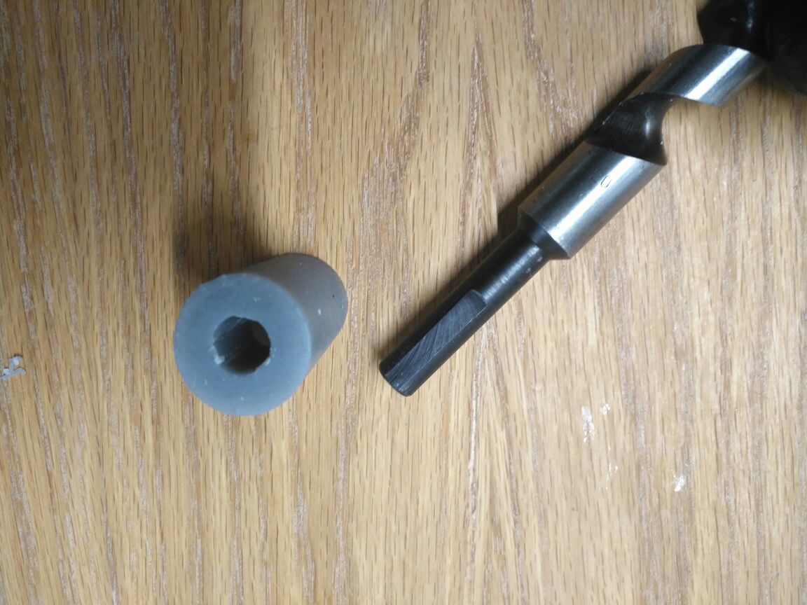
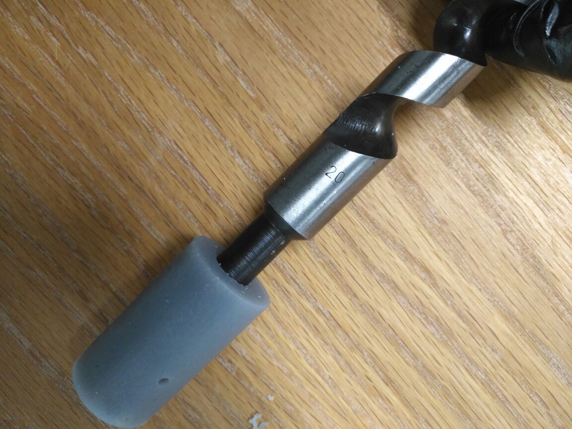
This is the moment of truth as the part fit perfectly from both sides.
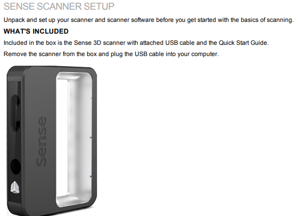
Download the Sense SOFTWARE
1. Navigate to Cubify.com.
2. Click Cubes+ Sense.
3. Click Tech Specs.
4. Click Download Software for your operating system.
INSTALL THE SENSE SOFTWARE
Follow the instructions to complete the software download and installation.
After the software is installed, you link the scanner to a Cubify account.
RUN THE SENSE SOFTWARE
When you installed the Sense software, a shortcut was created on your desktop. Use the shortcut to open the application.
Note: If the scanner is not connected to your computer, a message will state "Device not connected." Plug the USB connector
for the scanner into the USB port on your computer.
You will then be prompted to activate your Sense 3D scanne

My colleague Nadine & I were discussing on what object we should be scanning for with the scanner; so we decided to scan each other and exchange the scanned files.

When you first open the software it requires an activation code and how to use it.

Here we have 3 options, object, head and body and I have chosen the head.

Nadine sat on the stool and I move in circle around her head and tried to fulfill all white spots.

After finishing she looked like having a double face most likely she was moving during the scanning or I didn't make a complete circle.

Here I tried again it was better but there are some blank places.

In the bar on the left there is a Solidify icon which covers all the blanks so now it is ready.
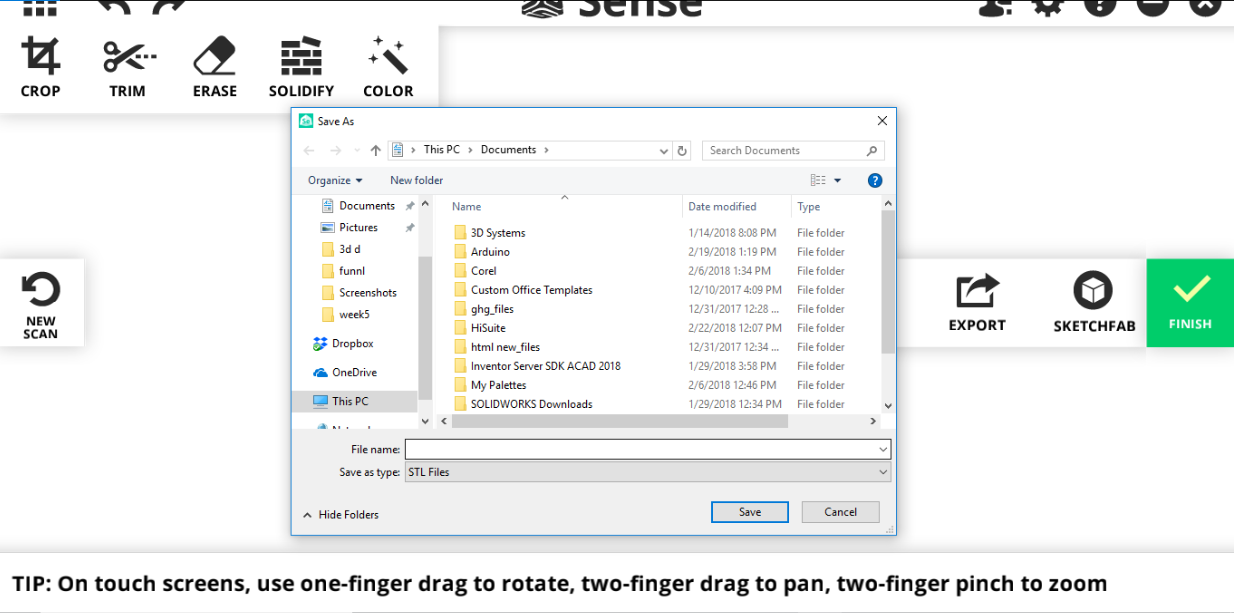
I saved as STL file and gave it to Nadine.
Nadine gave the file for the scan she made for me.
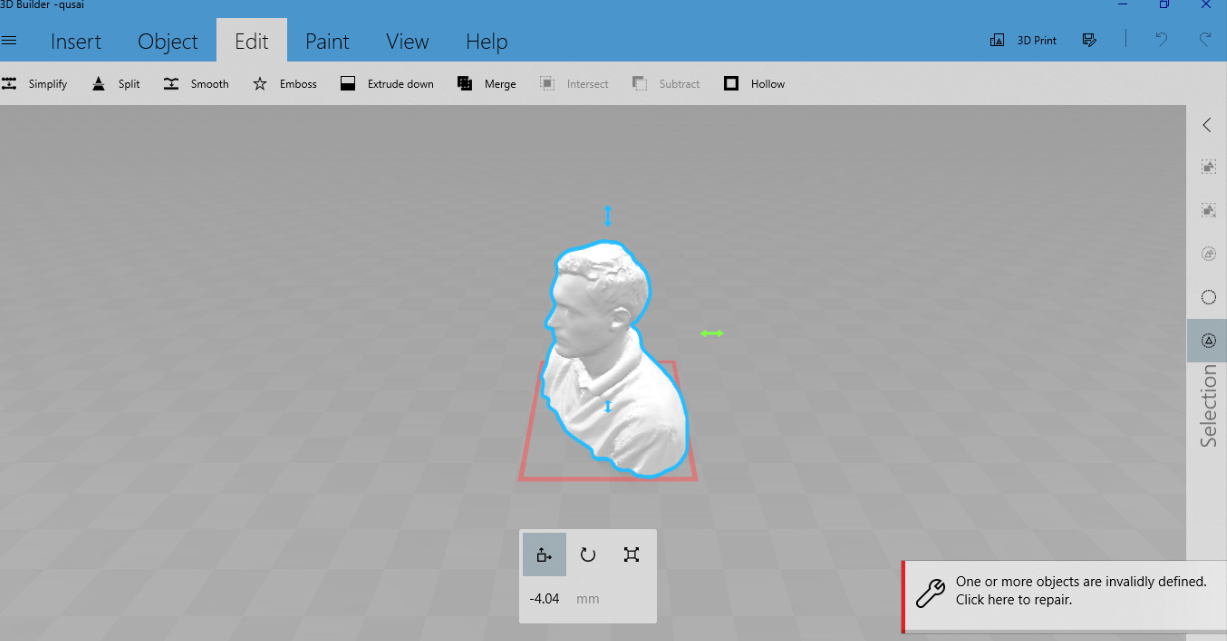
I have exported the file to 3D builder software. this software is part of Office; it is not that powerful but the good thing about it is that you can edit the STL file.
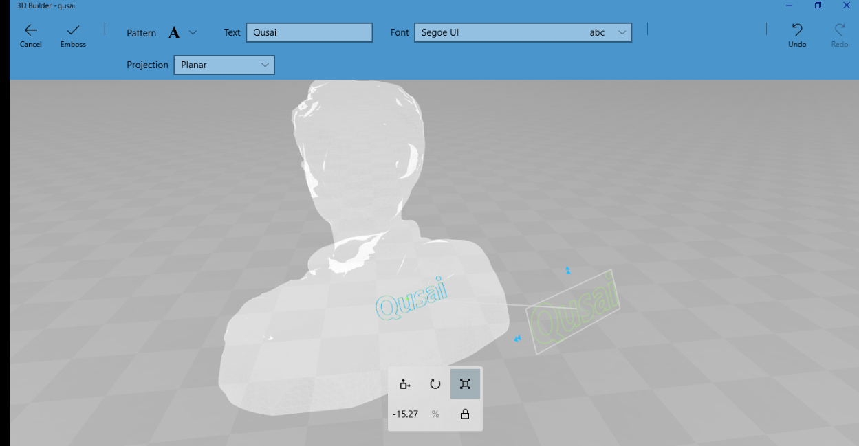
I have added some text and my name on the back then save it again as STL
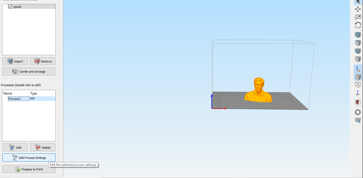
I exported the file to simplified 3D which works like CURA but it is not an open source it enables you to go deeply into the settings.
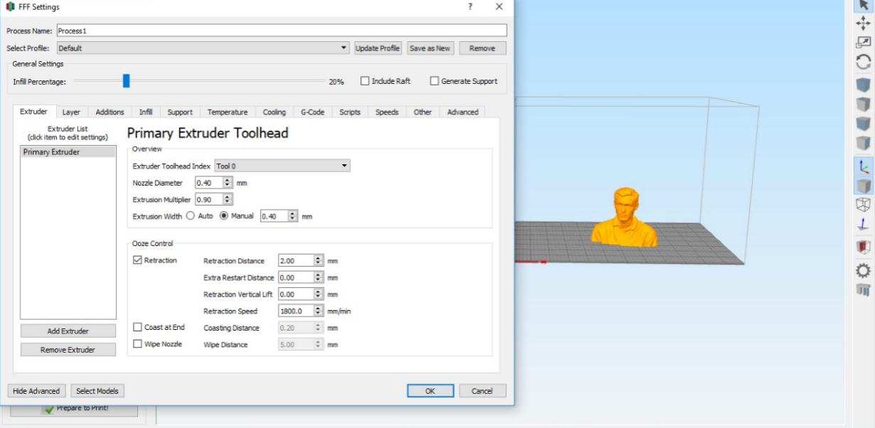
I went to edit process settings where you can choose the kind of printer to be used and the whole settings. I put normal settings as I wanted to print fast. The machine I have chosen Witbox 2.
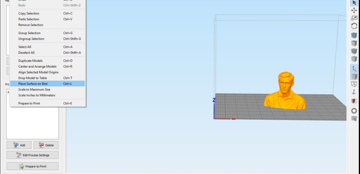
To make sure that the model will be flat on the surface press Control Shift & L and choose where to touch the bed.
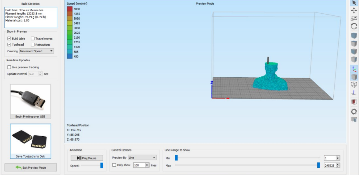
I have chosen prepare to print it will show the layer view, how many grams of material will be used and timing. I save it on SD card as a G code to send to the printer.
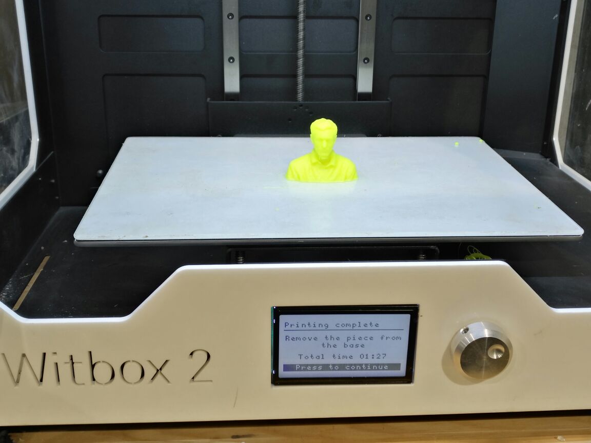
This is the print after printing inside the Witbox 2 . The beauty of Withbox 2 printer is excellent with printing flexible material. I have chosen Filaflex material.
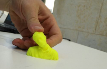
This is me as a stress ball so to squeeze my head when I am stressed and not the head of anyone else (;
Download the files
Download the motor_holder
Download the funnl
Download the Qusai scan


