This is a second week assignment for the Fab Academy 2018.
The software I have used




I was so excited to use new softwares for 2D & 3D and to be able to learn to use new softwares. the 4 software I have used which are:
solidworks tutorial
I have started working with Solidworks which has great tutorial to lead you through what you need to do for parts, assembly& drawing.
If you tag help and choose Solidworks tutorial will take you to the guide shown on the right side
1.Click New
2.In the New SOLIDWORKS Document dialog box double click Part.
3.Click Save
4.In the dialog box, type Tutor1 for File name
5.Click Save.
1. Click Extruded Boss/Base
2.Select a plane
3.Click Corner Rectangle
4.Move the pointer to the sketch origin
5.Click the origin and drag the pointer up and to the right. Notice that it displays the current dimensions of the rectangle
1.Click Extruded Boss/Base
2.Click Normal
- Click Extruded Cut
- Click Normal
- Click Circle
- Click Smart Dimension and set the diameter of the hole to 50
- Click Fillet
- Under Fillet Type, click Constant Size Fillet
- Under Fillet Parameters
- Select the four edges at the corners of the base
- As you select each edge, its name is added to Edges, Faces, Features and Loops
- Click Rotate View
- Click Shell
- Under Parameters, set Thickness to 2
I have followed the steps so I have finalized all from the parts to drawings as shown above
I highly recommend that Solidworks tutorials to be used by all as he/she will learn a lot and facilitate the work
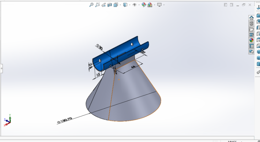
I did my first part for my final project on Solidworks which is the Funnel
plane before loft
First I created two parallel planes
2d sketch loft
Then I have made a sketch in 2D a circle then I used loft to complete it.
lofted cut
Then I sleeted the 2 drawings I used loft cut
extrude after loft
Then I extruded the rectangle to add a holder to connect the funnel to the pipe
clamp extrude
Then I drew half a circle and I used boss/extrude on both directness and added the by drawing a rectangle and extrude
clamp circle cut
chamfering_plane
When I created the clamp there was an extra material so I used chamfer to remove it
chamfering section view
Then I added holes for screws as seen .I did that by drawing a circle and cut extrude it
holes
Parametric
 Download Funnel Design
(AutoCad)
It's the first time for me to use AutoCAd I started drawing 2D modelling for a box which will be connected by joints. I have viewed many tutorials on YouTube which was very helpful. AutoCAd is cool as you can find the by making search for the command you are going to use.
basic
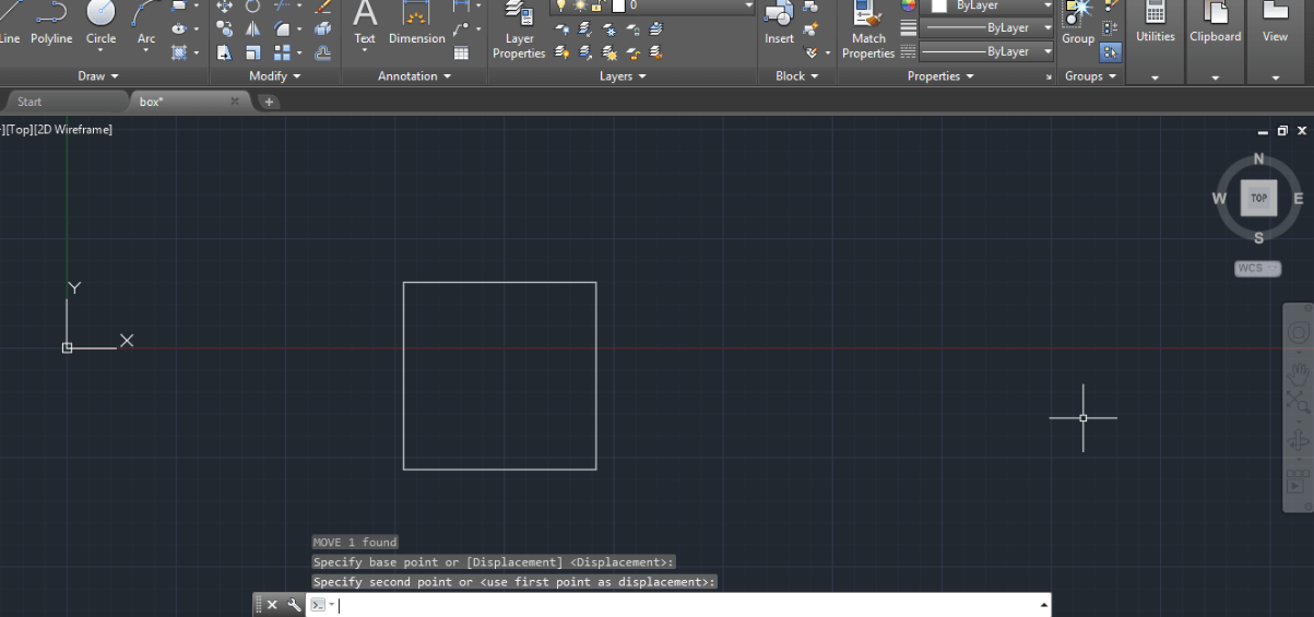
I started with a rectangular base and I gave it the following Dimensions 22.cm* 23.cm
Darw
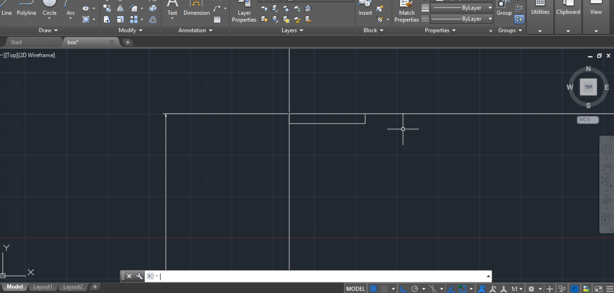
Then I started to draw the hinges with 4.5cm*0.78 as shown
Trim
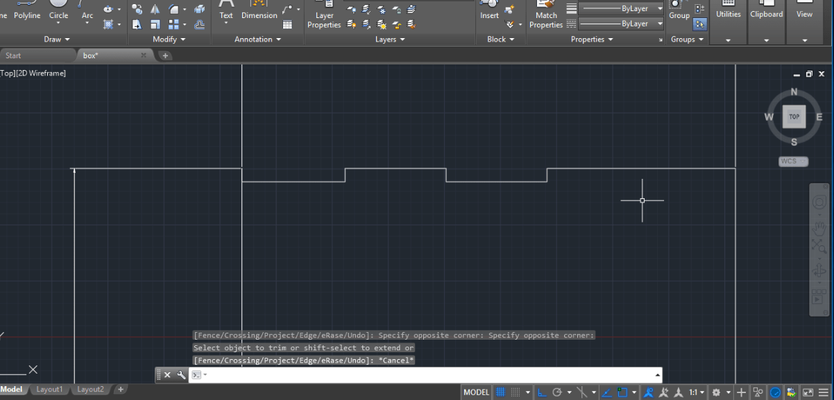
Then I have to trim the excess so I used the command trim as shown
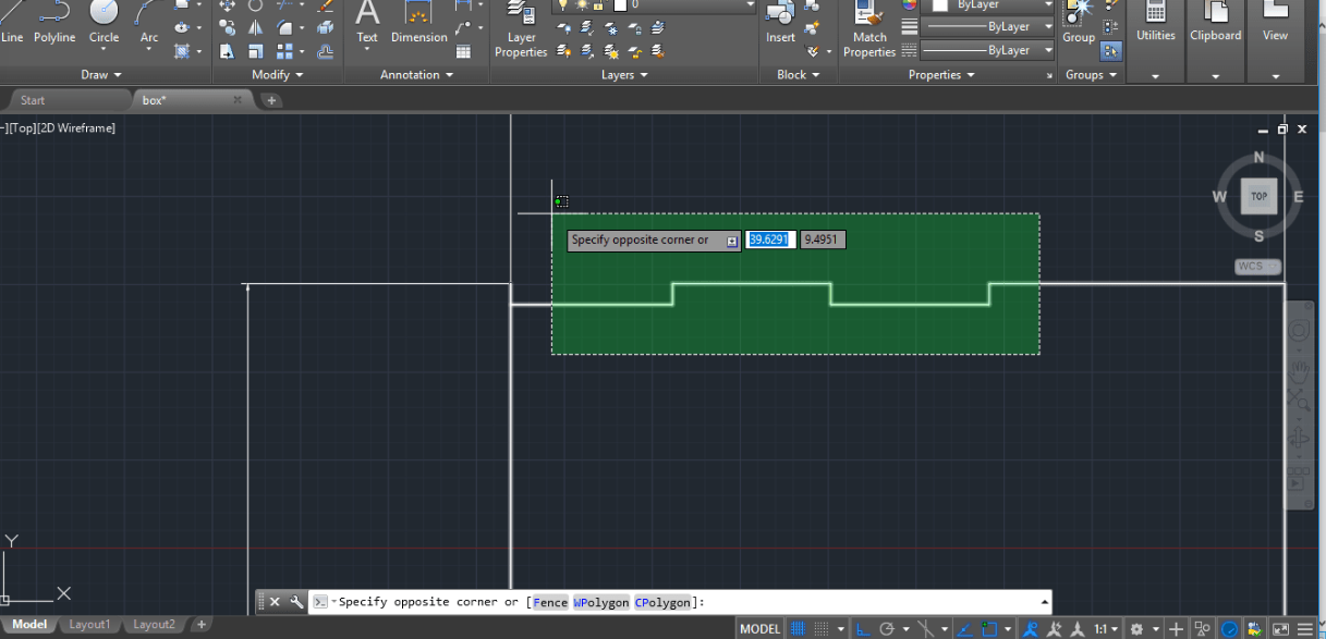
selecit
To make sure that my dimensions are correct so I used scale
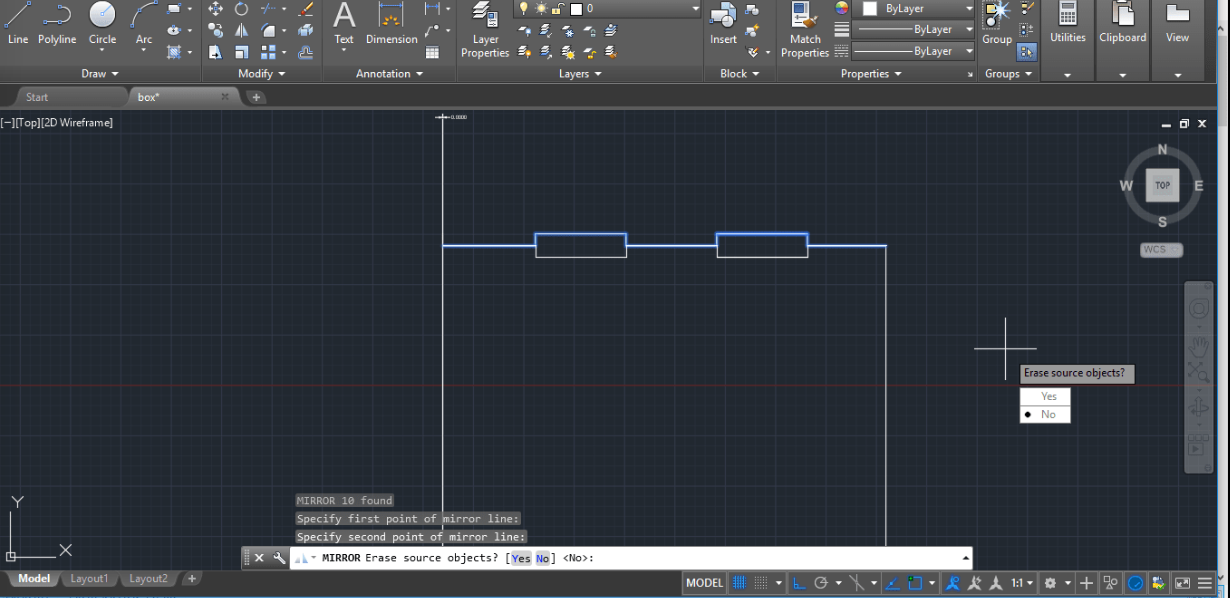
after mirror
I have made a re-drawing the hinges .I chose to mirror them as shown
Mirror
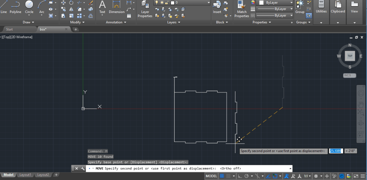
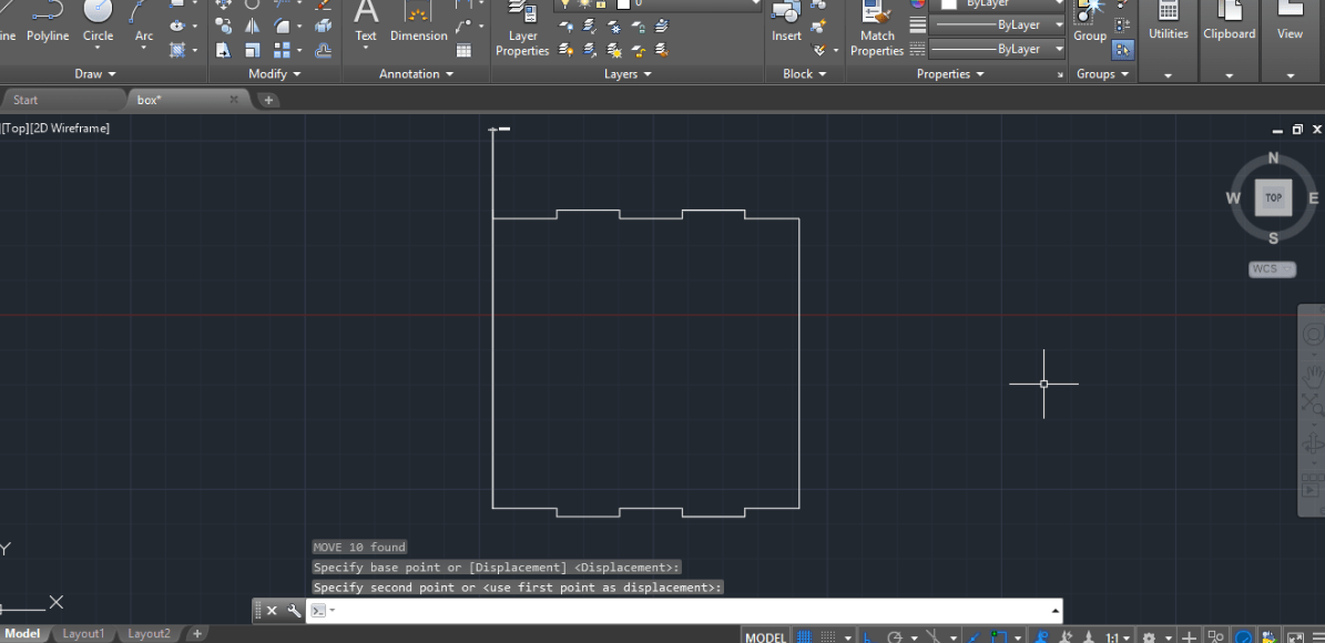
rotate
To draw the hinges from left to right I copied the one I made then I rotated them 90 degrees
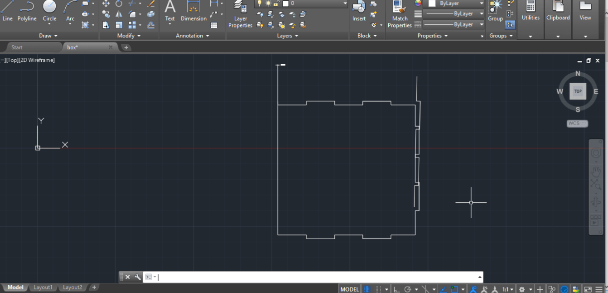
error
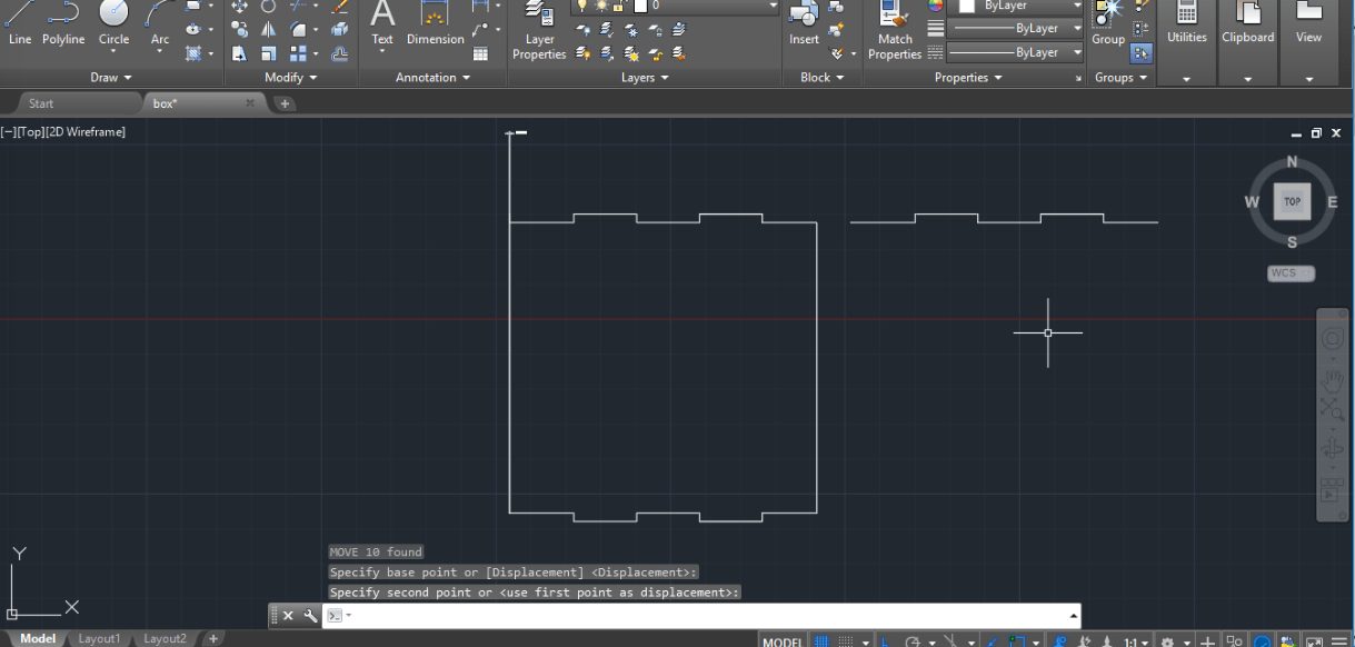
I wanted to mirror from the right to the left but I perceived that there was an error .The two lines at the top left corner were not connected so I used to fillet command to connect them
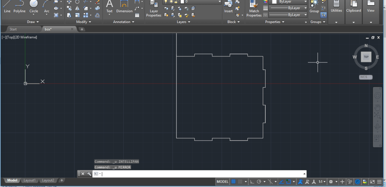
undo
11.png)
after mirror
Then i mirrored it again and it work it
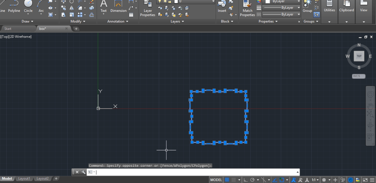
all right
To make the other face i selected everything and i copied it
The other sides of the box are to be continued next week for laser cutting
I have started using fusion 360 from Autodesk; also I have reviewed some tutorials on the YouTube. I found that the interface on the fusion 360 is helpful and can be adopted quickly and it is biometric software so I prefer to use it. I’ll start drawing a door for my Ultimaker 3 extended. Iwll use acrylic 3 mm thickness materials to laser cut it. Processes are explained bellow:
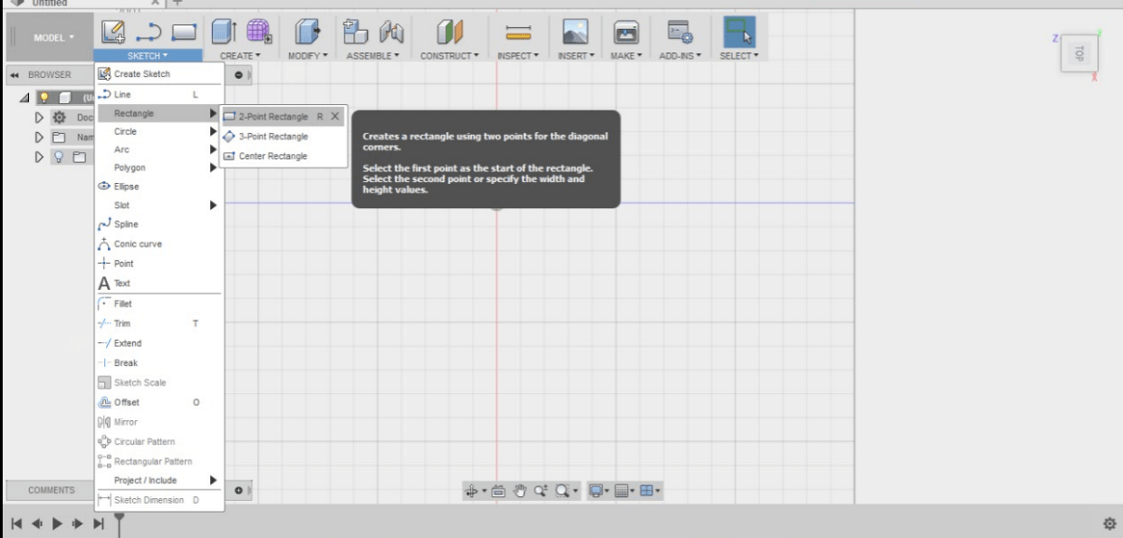
First I have chosen the top plane then from sketch I have chosen rectangle.
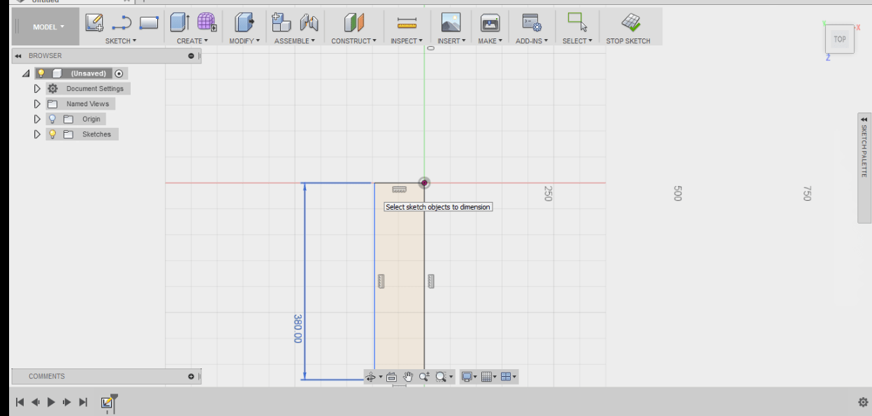
Started drawing the rectangle and added the dimensions.
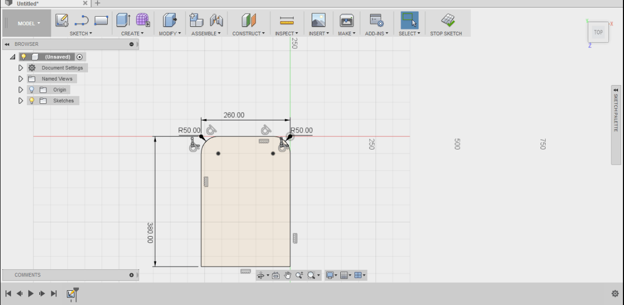
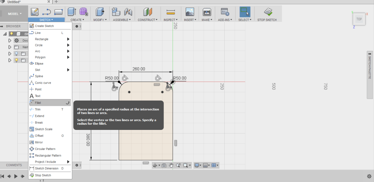
Then I did the fillet for the corners fillet command can be reached at sketch command.
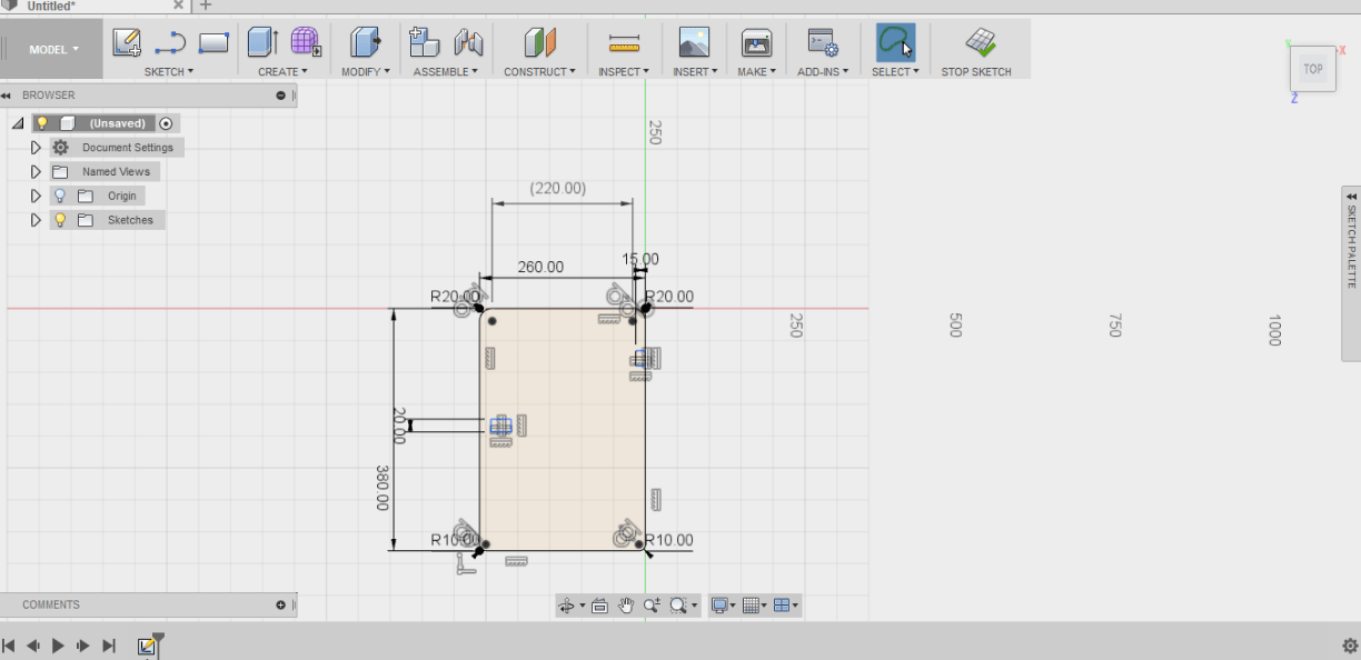
I have made drawing for the handle knob.
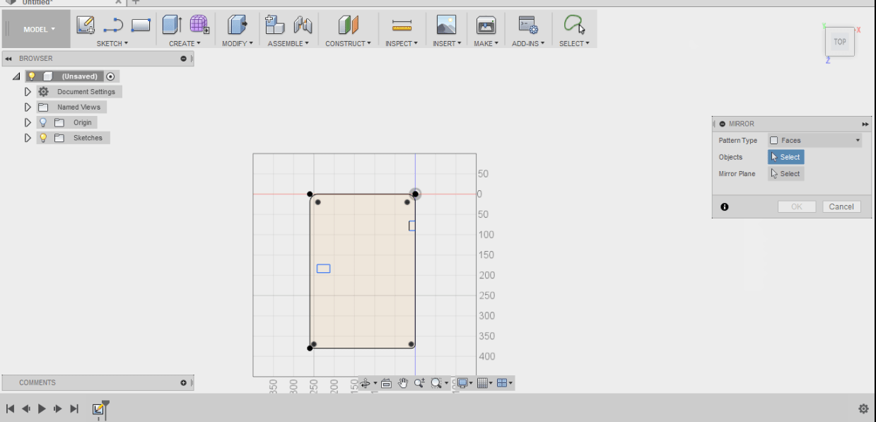
I have added drawing for hinges opening.
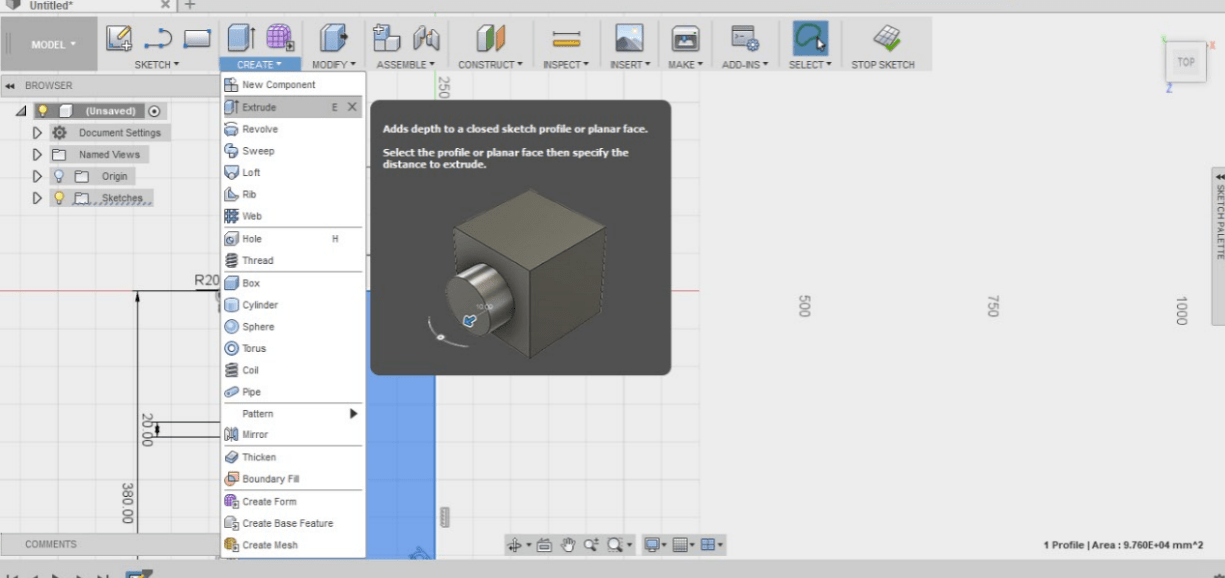
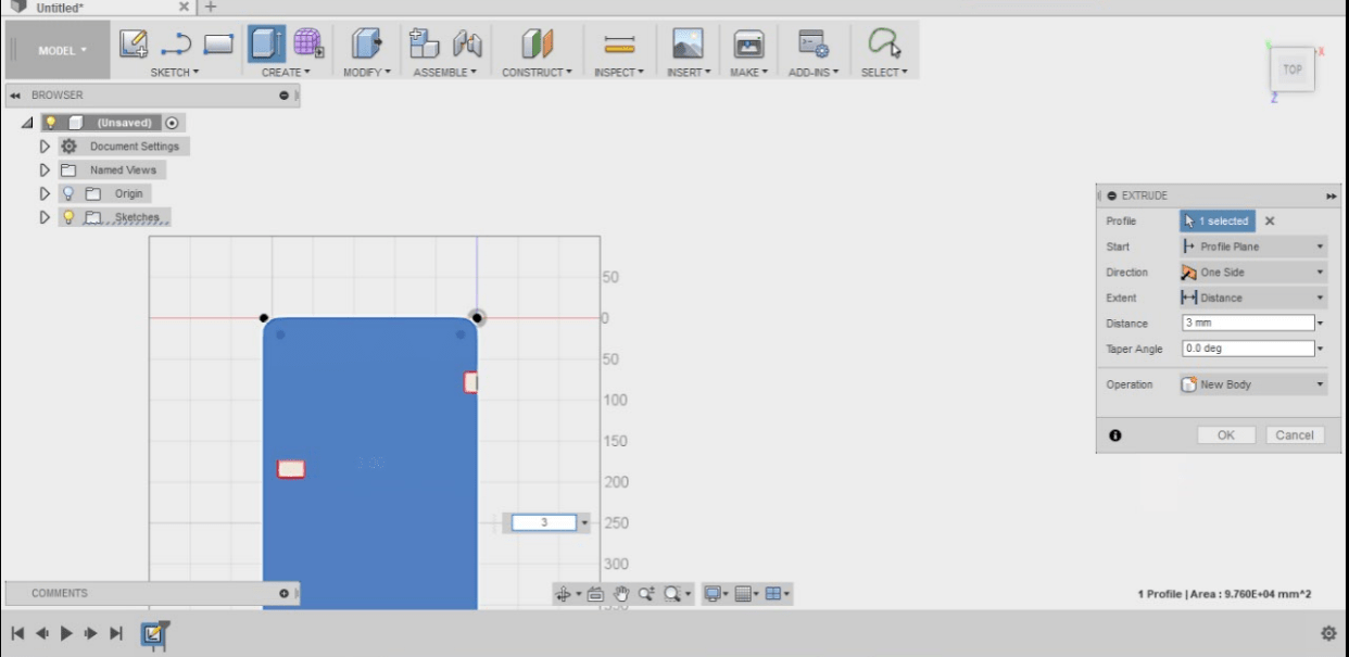
Then I have extruded I; extrude can be reached from create.
After extrude I have chosen the thickness of 3 mm.
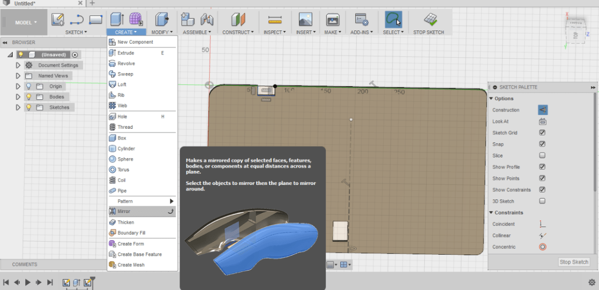
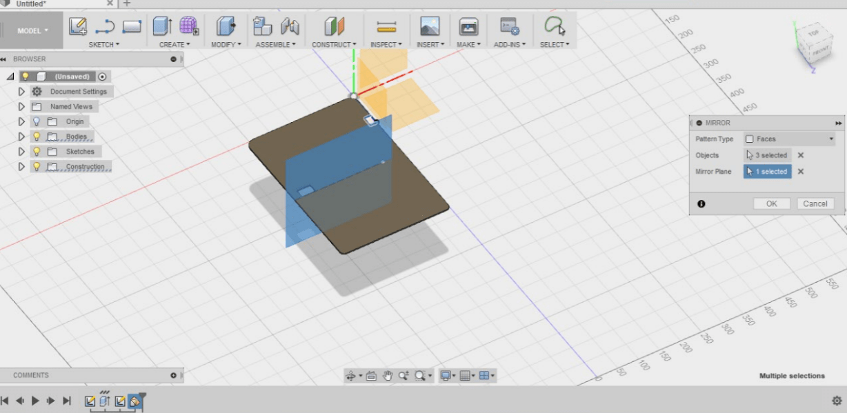
I have made a mirror for the opening hinges; I made access in the center of the mirror.
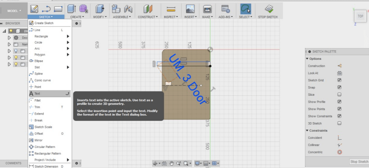
I have added a text the text command is found in the sketch command.
Download the DesignI was planning on using rhino software but unfortunately I didn't have enough time to. Hopefully i will use it sometime soon
