Machine Building
This documentation covers 2 weeks which are the Mechanical Design Week and the Machine Design Week.
Machine Design Week
This week's assignment; is to start designing & assembling a machine that we want to build. We were all excited about this week from the beginning of Fab Academy. We already had an idea of what we wanted to do before. We wanted to do something that reflects our culture, so the ideas were:
- Arabic Caligraphy Machine.
- Henna Drawing Machine.
- Qatayef Maker
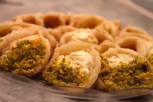
With Ramadan being right across the corner (NEXT WEEK) this is a perfect machine to build!
Our machine will be making the dough but we will have to fill it in manually (or maybe we can think of something while we're programming it to reduce the man labour required to eat this delicious dessert!)
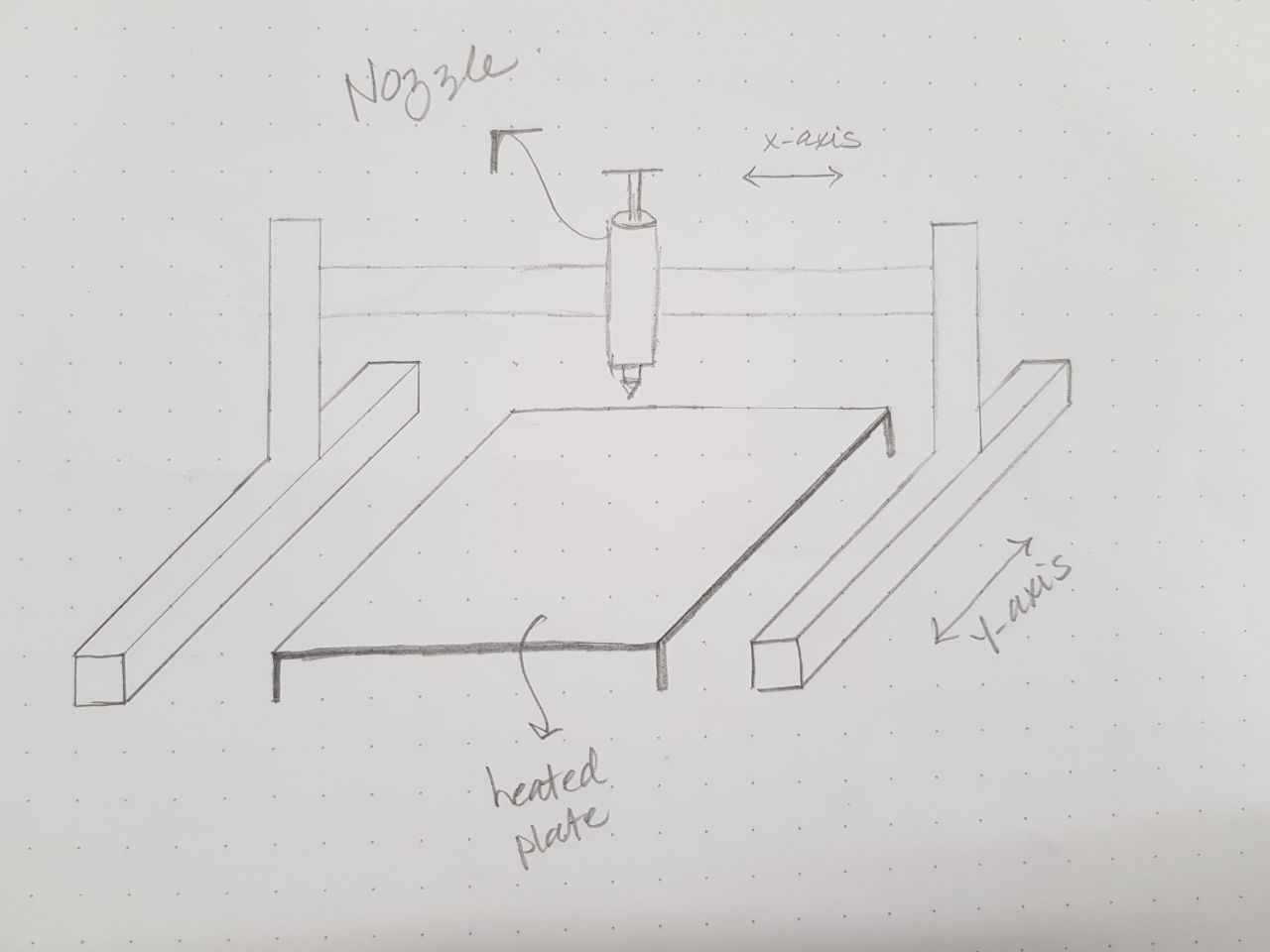

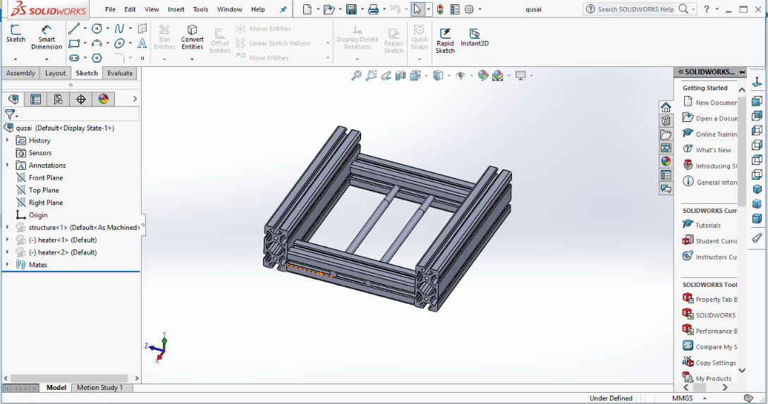
Each one of the group was assigned with part of the group project; my assignment in this project was to design the base for the machine also the frames. We decided to use Aluminum Linear Guides for the frames. Also I was designated to be in charge for the heating system of the machine; so I took great effort with the design so the heating system and the heated plate will fit perfectly.

To join the Aluminum files together we needed to use angles. So I designed the required angles on Solidwork and also I printed the T slot but it didn't work as the screws didn't screw up perfectly so we used instead of T slot nuts M4 and the angels was 3D printed in PLA filaments. Our concerns were as Aluminum carry the heat and it might melt the angles as temperatures reach over 200 degrees C, so we have decide to fix the angles from the outside of the frame.


Most of the parts which were designed by the team members were sent to me to make slicing for them to prepare for 3D printing and we used Ultimaker 2+ and 3 Extended as some parts with a length over 25 cms.
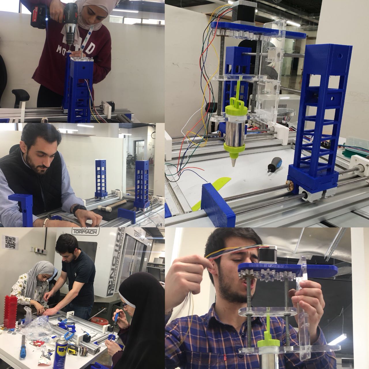
Most time consuming was the assembly as we faced some issues as we needed to grind some parts so to fit exactly; for more details you can check the Group assignment to see the full details and issues we faced. The machine is working and we can move the Axes by hand.
Download
Mechanical DesignMachine design
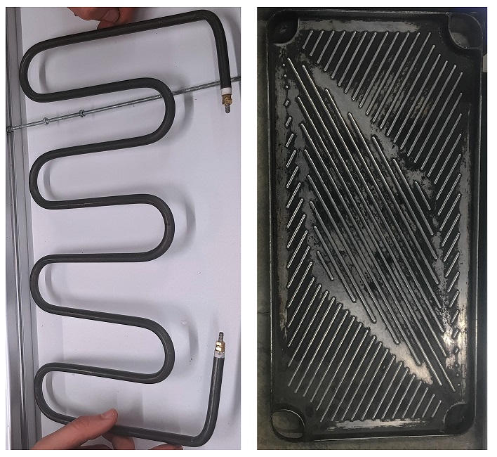
This week my assignment was to take care of the heated bed.
We thought of many ideas how to heat the bed and to ensure that the bed is food safe; I found locally a heating element 220 Volts and then we made the bending for it so it will fit exactly under the bed and the heat the heat to be distributed equally on the bed.

First step was fixing the heat element to the plate; at first I thought of welding it but we don’t have the special welding need for aluminum so I thought of bringing a sheet of metal and made drilling for it from top and bottom and made sure that the heat element is stuck to the plate so not to lose and heat.
Control of the heat element; I used relay SSR50DA and connected it between the power source, heater and Arduino.
To ensure that it is well working I made trouble shooting with a lamp as you can see the lamp is blinking as I was sending pulses on the code.
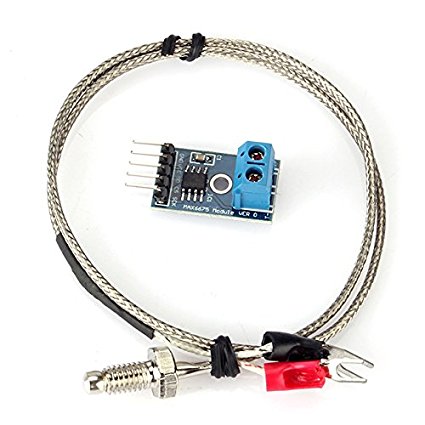
Thermocouples have been around forever and are a great way to measure temperature. They have a very large range, are robust and come in all kinds of lengths, varying tip configurations and a variety sheaths. The challenge with using thermocouples is with the need for what is known as cold junction compensation and the need to detect a very small voltage change for every degree in change of temperature.
IMPORTANT NOTE_ Most K thermocouples come with a red lead and a yellow lead. The red lead is normally your negative connection and the yellow lead is your positive. That is industry standard.
I connected it to the thermo cable to observe the readings on the serial monitors and the maximum reached 236 degrees C which is enough for cocking the Qatayef.
#include
  // Sample Arduino MAX6675 Arduino Sketch

#include "max6675.h"

int ktcSO = 8;
int ktcCS = 9;
int ktcCLK = 10;
#define LED_BUILTIN 7

MAX6675 ktc(ktcCLK, ktcCS, ktcSO);


void setup() {
  Serial.begin(1200);
  // give the MAX a little time to settle
  delay(5000);
   pinMode(LED_BUILTIN, OUTPUT);
}

void loop() {
  // basic readout test
  digitalWrite(LED_BUILTIN, HIGH);   // turn the LED on (HIGH is the voltage level)
//  delay(1000);                       // wait for a second
//  digitalWrite(LED_BUILTIN, LOW);    // turn the LED off by making the voltage LOW
//  delay(1000);
   Serial.print("Deg C = ");
   Serial.print(ktc.readCelsius());
   Serial.print("\t Deg F = ");
   Serial.println(ktc.readFahrenheit());

   delay(5000);
   }
Here is the code for the Arduino I used.
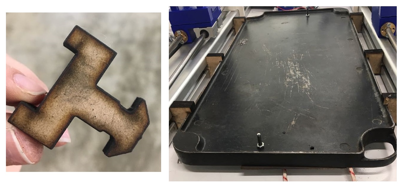
8. After ensuring that the system is working well we needed to fix on the machine but we faced a problem of how to fix it on the machine. So we thought to make metal T slots but it will be heat connecting and might melt the 3D printed parts so we thought to us MDF and we made a design for the slots then we made many trouble shotting till we got it to fit perfectly. As we have MDF with 5 mm thickness only so we glue two parts together so to be stronger and hold the parts and it worked well.
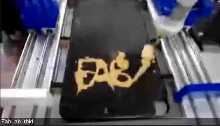
It was quite a challenge to come within two weeks time frame with an idea for a machine, design it and building it but being part of a great delegated team who will not think of the time but how to get the job done we were able to get the assignment fully working and we eat Qatayef we made on that machine. Thanks to all the team members and I am proud to be part of this team. Check the link for the whole process.
Future Improvements
When we have time, we can 3D Print the extruder using PCTG Food Safe material to make it lighter and fit better with our design, since we had a problem with finding a suitable cream pump form the market.
Another area that we could improve is the aluminum linear guides that we used as the chassis, it made the machine heavy, and I think we can design other chassis using acrylic or wood to make it lighter and easily replicated in any fablab.
