This is the twelfth week assignment for the Fab Academy 2018.
.Interface and Application Programming
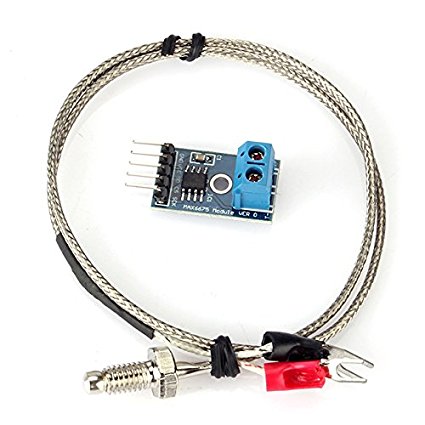
The assignment for this week was to write an application that interfaces with an input or an output device. I used the temperature sensor and the buzzer
Process

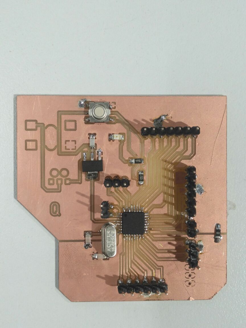
I used the ATMEGA328 which is my arduino the one I built in Electronics production.
Application Programming is a whole new topic for me so my first step was to browse through some different application programming interfaces and choose the one that seemed the easiest for me to use. So, as I was browsing through the different interfaces I stumbled upon Processing
Processing can be used also with Arduino. After figuring out how to get started with Processing, I followed up some of its tutorials. After I understood how it works and what I am capable to do with that program, my next step was to figure out how to use it with Arduino. So, for that after a little bit of more searching, I followed up this Sparkfun tutorial which was very helpful.
(k) type thermocouple

/*
  // Sample Arduino MAX6675 Arduino Sketch

#include "max6675.h"

int ktcSO = 8;
int ktcCS = 9;
int ktcCLK = 10;

MAX6675 ktc(ktcCLK, ktcCS, ktcSO);


void setup() {
  Serial.begin(1200);
  // give the MAX a little time to settle
  delay(5000);
}

void loop() {
  // basic readout test

   Serial.print("Deg C = ");
   Serial.print(ktc.readCelsius());
   Serial.print("\t Deg F = ");
   Serial.println(ktc.readFahrenheit());

   delay(5000);}
   "
Here is the my arduino code
                        //import Serial communication library
                        import processing.serial.*;
                        //init variables
                        Serial commPort;

                        int yDist;
                        int xPos = 1;         // horizontal position of the graph
                          float inByte = 0;
                        float[] tempHistory = new float[100];

                        void setup()
                        {
                         //setup fonts for use throughout the application
                        //set the size of the window
                         size(200,200);
                        //init serial communication port
                         commPort = new Serial(this, "COM7", 1200);
                        //fill tempHistory with default temps
                         for(int index = 0; index < 100; index++)
                         tempHistory[index] = 0;
                        }

                        void draw()
                        {
                         //get the temp from the serial port
                        //refresh the background to clear old data
                         background(123);

                         //draw the temp rectangle
                         colorMode(RGB, 160);  //use color mode sized for fading
                         stroke (0);
                         rect (49,19,22,162);
                         //fade red and blue within the rectangle
                         for (int colorIndex = 0; colorIndex <= 160; colorIndex++)
                         {
                         stroke(160 - colorIndex, 0, colorIndex);
                         line(50, colorIndex + 20, 70, colorIndex + 20);
                         }

                        //draw graph
                         stroke(0);
                         fill(255,255,255);
                         rect(90,80,100,100);
                         for (int index = 0; index<100; index++)
                         {
                         if(index = 99)
                         tempHistory[index] = inByte;
                         else
                         tempHistory[index] = tempHistory[index + 1];
                         point(90 + index, 180 - tempHistory[index]);
                         }
                        //write reference values
                         fill(0,0,0);
                        textAlign(RIGHT);
                         text("e; 500 C"e; , 45, 25);
                         text("e;24 C"e;, 45, 187);
                        //draw triangle pointer
                         yDist = int(160 - (160 * (inByte * 0.01)));
                         stroke(0);
                         triangle(75, yDist + 20, 85, yDist + 15, 85, yDist + 25);
                        //write the temp in C and F
                         fill(0,0,0);
                        textAlign(LEFT);
                         text(inByte +  C"e;, 115, 37);

                         }


                          void serialEvent (Serial myPort) {
                            // get the ASCII string:
                            String inString = myPort.readStringUntil('\n');

                            if (inString != null) {
                              // trim off any whitespace:
                              inString = trim(inString);
                              // convert to an int and map to the screen height:
                              inByte = float(inString);
                              println(inByte);
                             // inByte = map(inByte, 0, 1023, 0, height);
                            }
                        }
Here is the my Processing code
I used processing to read the data from a temperature sensor and display it on an interface, to do that, I created two rectangles, the first shows the history of the reading and the second indicates the current reading.
I also created a triangle to indicate the current reading and I did that using the position coordinates of the triangle. I also created a separate function to read the serial data that's coming in from the arduino.
Creating a two button graphical interface in Python to control a Buzzer
I will use Python . programming language to achieve this. The software which I will write, will communicate with the Arduino using Serial Communication
int buzr=12; // the buzzer is connected on pin 12


void setup() {
  // put your setup code here, to run once:
Serial.begin(9600);  // baudrate is 9600, and should be the same as in the python code
pinMode(buzr, OUTPUT);  //define the buzzer as output
}

void loop() {

  // put your main code here, to run repeatedly:
int val=Serial.read();  //read the serial which is sent from the python interface
if(val=='1'){ // if it receives a 1, turn the buzzer on
  digitalWrite(buzr, HIGH);
}
else if (val=='0'){ // if it receives a zero, turn the buzzer off
  digitalWrite(buzr,LOW);
}

}
Here is the my arduino code
import serial
from tkinter import *

arduinoData = serial.Serial('com7','9600') //connect to the arduino on port 7 and with baudrate of 9600

def buzr_on():
     arduinoData.write(b'1')   // if the on button on the interface is pressed, send 1 to arduino


def buzr_off():
     arduinoData.write(b'0')    // if the on button off the interface is pressed, send 0 to arduino


buzr_control_window= Tk()   // draw the window of the interface

btn=Button(buzr_control_window,text="Turn Buzzer ON ",command=buzr_on, height=6, width=15)  // define the function when the button is pressed
btn2=Button(buzr_control_window,text="Turn Buzzer Off ",command=buzr_off, height=6, width=15)  // define the function when the button is pressed

btn.pack() // add the on button to the window
btn2.pack() // add the off button to the window

buzr_control_window.mainloop()
In the above code, you can see that I imported the serial library to communicate with my arduino board using the serial port.
After that I also imported the tkinter library which is the library responsible for drawing shapes and graphs. I defined that I will be use the (com7) port with a baud rate of 9600 just as specified in arduino.
Then I defined the two functions I will be calling when the buttons are pressed. The interface I was trying to program was simple, two buttons, one turns on the buzzer and another one turns it off. So I defined the buttons and specified the function it will call when it's pressed.
At first I ran the program without putting the .pack() and it opened an empty window then I figured out that I have to actually draw them on the window.
Problems
I had a problem with the readings showing in the processing code as it was showing wrong readings. So when I went back to the code, I noticed that I had mapped the readings wrong so I removed the mapping and readings were matching the ones from the arduino serial monitor.
Download
temp_k_typeprocessing_code
buzzr_code
python_code
