This is the eleventh week assignment for the Fab Academy 2018.
.Output devices
Made a new board for the input and output device

In the above image you can see the board which I have created for this week. As you can see all the components are already soldered except for the Max chip because that chip isn't easy to find here so I used a commercial one.

I chose to do some fixes on the ATMEGA328P micro-controller board I worked on Electronics Design (week #6). I wanted it to be as similar as possible to the board I'm going to use for my final project. I made the below changes

I added a Full-Bridge DMOS PWM motor driver to the board instead of the L298N Dual H-Bridge 3A Motor Driver Board to control my DC motor.

I added a MAX6675 chip directly to the board as an amplifier to control the thermocouple K-type. This will result in less cables coming out of the board, and I won't have to keep connecting wires with another device.
DC Motor
This week for the output devices I focused on motors (DC) I chose DC motor as this is the type of motor I’ll be using for my final project so I have made thorough searches about types of motors; The best motor I found will be most suitable and available in our lab is DC Motor with Gearhaed 12VDC 74 mA. As we are approaching towards the final project every week I save no efforts to search of what I can use for my final project and make a trouble shooting to be ready.


Also I used the ATMEGA328 which is my arduino the one I built in Electronics production.


This is the DC motor I used and you can see its features. I want a motor which gives high torque so to move the lead screw easily so to move the materials. If upon trial this motor doesn’t give the required torque I’ll be looking for another motor.

.jpg "L298N")
In this tutorial Thay explain how to use our L298N H-bridge Dual Motor Controller Module 2A with Arduino. This allows you to control the speed and direction of two DC motors, or control one bipolar stepper motor with ease. The L298N H-bridge module can be used with motors that have a voltage of between 5 and 35V DC

Here are the connections between the arduino and H-Bridge.with the H-Bridge you can connect up to 2 motors.

I removed the arduino and I used FTDI Cable for the first time and you can see here the connections it worked well but you need to remember to switch between TXD & RXD

I connect with FTDI cable and you can see that I didn't used the bread board as there was enough pins on the board.
// connect motor controller pins to Arduino digital pins
// motor one
int enA = 10;
int in1 = 9;
int in2 = 8;

void setup()
{
  // set all the motor control pins to outputs
  pinMode(enA, OUTPUT);
  pinMode(in1, OUTPUT);
  pinMode(in2, OUTPUT);
}

//
//}
void loop()
{
  digitalWrite(in1, 0);
  digitalWrite(in2, 1);
  analogWrite(enA, 500);
delay(5000);

   digitalWrite(in1, 1);
  digitalWrite(in2, 0);
    analogWrite(enA, 500);
delay(5000);

}
Here is my code

In this code I first programmed the motor to turn in one direction giving in1 a value of zero and in2 a value of 1 and the set the speed by giving the pwm value of 500 to the enable.
Then I reversed the direction of the rotation by flipping the values of in1 & in2.
As you can watch in the video the lead screw is moving in both directions.
Heater
Now I moved on to the 2nd output device which is a heater. I will be using this heater for my final project to heat the extruder. This heater is custom made to fit on my extruder, I will talk about in details in my final project documatnation.
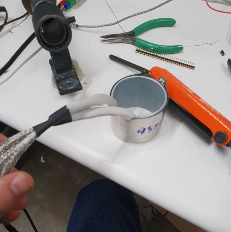

This heater operates on a 12V and I used a solid-state relay as seen above to be able to control the temperature.

I also used a K-type thermocouple to be able to get the reading from the heater just like I did last week.
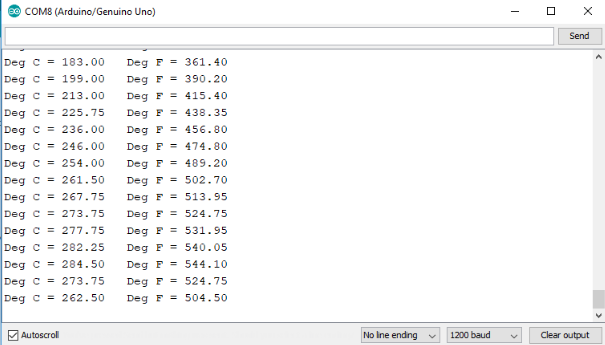
The above image shows the readings from the serial monitor. As you can see it managed to heat up to 260 degrees celsius which is more than enough for my filament recycling extruder. You can find my code below.
#include
  // Sample Arduino MAX6675 Arduino Sketch

#include "max6675.h"

int ktcSO = 8;
int ktcCS = 9;
int ktcCLK = 10;
#define LED_BUILTIN 7

MAX6675 ktc(ktcCLK, ktcCS, ktcSO);


void setup() {
  Serial.begin(1200);
  // give the MAX a little time to settle
  delay(5000);
   pinMode(LED_BUILTIN, OUTPUT);
}

void loop() {
  // basic readout test
  digitalWrite(LED_BUILTIN, HIGH);   // turn the LED on (HIGH is the voltage level)
//  delay(1000);                       // wait for a second
//  digitalWrite(LED_BUILTIN, LOW);    // turn the LED off by making the voltage LOW
//  delay(1000);
   Serial.print("Deg C = ");
   Serial.print(ktc.readCelsius());
   Serial.print("\t Deg F = ");
   Serial.println(ktc.readFahrenheit());

   delay(5000);
   }
Problems
When I started soldering the traces of the chip were so thin and I accidentally created a short connection while soldering so I used the desoldering pump to remove the short then I switched to another soldering iron with a finer tip.
Download
a new board for the input and output devicea new board for the input and output device dc_moto
