This is the tenth week assignment for the Fab Academy 2018..
Input devices
This week we had to use input device; so we tested with different input devices. My focus was on temperature sensors so I used thermocouple(K)type and LM35 the reason behind my focus on this so to get acquainted as much as possible with the temperature sensors as it will be major part of my final project.
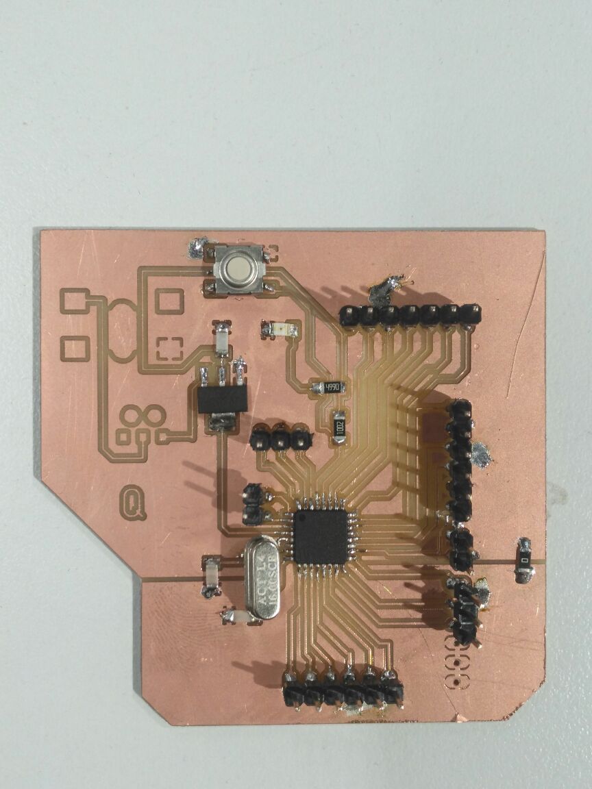
I used the ATMEGA328 which is my arduino the one I built in Electronics production.
(k) type thermocouple
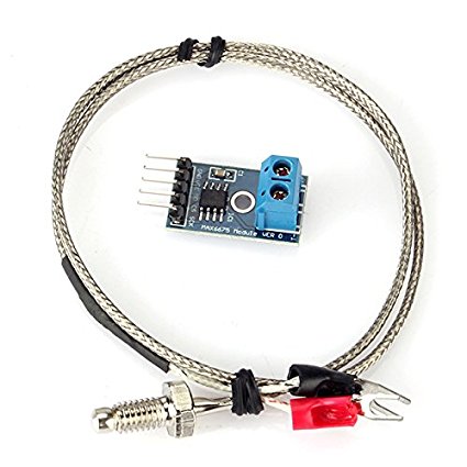
Thermocouples have been around forever and are a great way to measure temperature. They have a very large range, are robust and come in all kinds of lengths, varying tip configurations and a variety sheaths. The challenge with using thermocouples is with the need for what is known as cold junction compensation and the need to detect a very small voltage change for every degree in change of temperature.
IMPORTANT NOTE_ Most K thermocouples come with a red lead and a yellow lead. The red lead is normally your negative connection and the yellow lead is your positive. That is industry standard. That said, some of the suppliers for the module will in fact jack this up and provide you a thermocouple with red indicating positive.
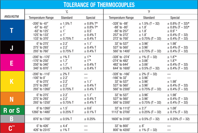
I decided to go with the K type because the temperature used for my final project will be around 200_250 degrees C and the K type can reach to 1260 degrees which will be more than enough moreover its design is very suitable with my design of the final project.
Fortunately there are chips like the MAX6675 that make connecting a thermocouple to your Arduino an affordable breeze. The device measures the output of a K Thermocouple and provides the result to the Arduino via a SPI interface.
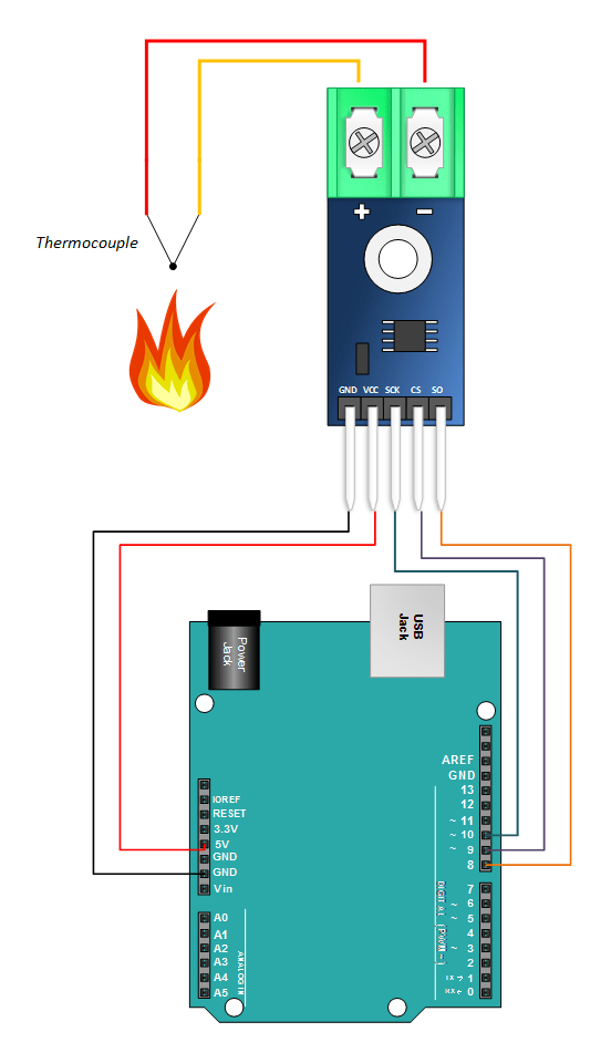
This is the connection with the arduino which I used for my arduino which I have built. Before using the FTDI cable I used arduino Uno for connecting the ground and VCC.
I have downloaded the MAX6675-library to the arduino through GitHub.
/*
  // Sample Arduino MAX6675 Arduino Sketch

#include "max6675.h"            // Include the library used

int ktcSO = 8;
int ktcCS = 9;
int ktcCLK = 10;

MAX6675 ktc(ktcCLK, ktcCS, ktcSO);      // ktc is a function inside the library I specified the clk, CS and S0 pins of the amplifier


void setup() {
  Serial.begin(1200);
  // give the MAX a little time to settle
  delay(5000);
}

void loop() {
  // basic readout test

   Serial.print("Deg C = ");
   Serial.print(ktc.readCelsius());
   Serial.print("\t Deg F = ");
   Serial.println(ktc.readFahrenheit());

   delay(5000);}
Here is the first code and I have uploaded it to my arduino; at the beginning I faced a problem as I kept getting error as for some reason it didn't read the Port so I removed all the entries in the USB then it was able to read COM.
Here is the video testing the K type thermocouple using the soldering Iron and you can notice the serial monitor readings in both in Celsius and Fahrenheit.
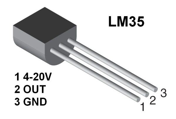
The LM35 is an ideal temperature sensor for measuring ambient temperature. It provides a linear output proportional to the temperature, with 0 V corresponding to 0 degrees C and an output voltage change of 10 mV for each degree C change. LM35s are easier to use than thermistors and thermocouples because they are so linear and require no signal conditioning. The output of an LM35 can be connected directly to a Arduino analog input. Because the Arduino analog-to-digital converter (ADC) has a resolution of 1024 bits, and the reference voltage is 5 V, the equation used to calculate the temperature from the ADC value is:
Temp=((5.0 * analogRead(TemperaturePin))/1024)*100.0
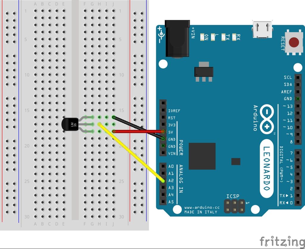
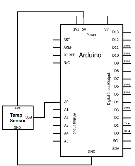
This is the connection for the LM35.
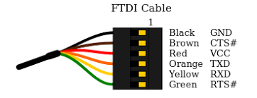
I removed the arduino and I used FTDI Cable for the first time and you can see here the connections it worked well but you need to remember to switch between TXD & RXD

I didn't put many pins in the board I have made earlier so I had to use breadboard also I connected the sensor to it also I took from my board to the bread board VCC & ground; another reason for using the breadboard is to make the two sensors work together.
#include "max6675.h"            // Include the library used
int value=0;            //initializing variables
float volts=0.0;
float temp=0.0;
float tempF=0.0;

int ktcSO = 8;
int ktcCS = 9;
int ktcCLK = 10;

MAX6675 ktc(ktcCLK, ktcCS, ktcSO); // ktc is a function inside the library I specified the clk, CS and S0 pins of the amplifier


void setup() {
  Serial.begin(1200);
  // give the MAX a little time to settle
  delay(5000);

}

void loop() {
    value=analogRead(A0);          //read from A0 the temp sensor
  volts=(value/1024.0)*5.0;      //conversion to volts
  temp= volts*100.0;
  // basic readout test
     Serial.print("lm35 = ");
   Serial.print(temp);

   Serial.print("Deg C = ");
   Serial.print(ktc.readCelsius());
   Serial.print("\t Deg F = ");
   Serial.println(ktc.readFahrenheit());

   delay(5000);}
This is the code and I have added to it extra and named the serial print LM35 so I can distinguish it.
Here the serial monitor for the two sensors working together.
This is a video and you can see how it reads the temperature from the lighter through the K type and the ambient temperature through the LM35.
Problems
Thanks to the power of internet and my dear good friend google, I didn't really face any problems connecting these input devices with my board.
Download
temp_k_typesensors_lm35_k_type
