Principles and Practices
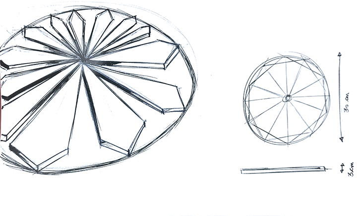
The endless possibilities that gridded geometry offers to 3D and 2D design is fascinating to me. Islamic Geometric Design has particularly caught my attention for a few years now. Hence, I plan on making my final project and exploration of the aesthetics and functionality of Islamic geometry by designing an object for interiors.
Inspiration:
Relief

Light

Tesselation

Sketch:
Function:
Beyond the timely reminder of identity and belonging, The wall clock will be a play on wood and light to convey time in an unexpected way. It will project light from within the clock as a message that can be read on the surface of the wood. The clock will hang as an object of decoration that tells time every 5 seconds.
I plan on making the final 2D design in illustrator, extruding the 3D shape in solid works, and printing a miniature clock using the Sindoh before I start working with actual wood. I will design the electronics separately until proven to work. Then mount everything into the final product.
Plan:
January - Inspiration and Research.
February - Skill Development (Design software, Electronics, 3D printing)
March - Final Shape 1st and 2nd drafts
April - Making the wooden shape
May - Making the circuit board
June- Mounting the circuitboard into the wood shape
Project Management
This was my first time coding, first time designing a website, and the first time I ever heard of Git. I had no idea what I got myself into, but here is my process.
- Step 0: Tools
First, is to understand that a Terminal is where all my coding activity will happen. A terminal is the Microsoft word for coding language. I found the Terminal built into my leptop (Command F> "Terminal") and I downloaded "Sublime" online. Sublime is a free color-coded software that helps write and read code.
- Step 1: Codecademy lesson
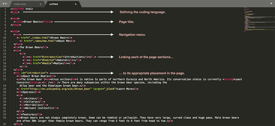
Codecademy HTML beginner lessons are a great resource to get you started in HTML. I highly recommend it. I used the Codecademy beginner code as a template, then I replaced the headline and paragraph content with my own.
Codecademy beginner code:
My additions: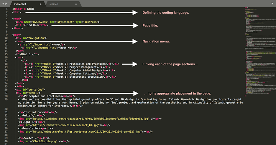
- Step 2: Reality Check
Until I did a tutorial I was still unaware of the gap between my vision and my skills. The first version of my website was almost discouraging.
- Step 3: Growth Mindset
Instead of giving into self-doubt, I decided to make the website a 6-months code project. In other words, I was okay starting at the basics as long as I make progress on the website over time. Over the weeks I will be adding CSS code in increments until the website is done.
- Step 4: What the heck is Git?
It is easy to get frustrated with jargon as a beginner. Until I found this tutorial, there was no way I could understand the Lecture on Git Commands. The tutorial goes over all the basics without being too overwhelming for beginners.
- Step 5: Puching and Committing Code
Here is the GitLab's quick guide to basic commands. However, even this guide can be disorienting. Therefore, once done with my code, Jonathan broke it down for me this way:
1. Learn what is the "ls" and the "cd" command in your Terminal. In brief, “ls” is the command that allows to list all items within a document in your computer, while “cd” is the command that allows to enter a document. Example: Let’s imagine I have only 2 documents in my entire computer “Document A” and “Document B”. “A” is where I keep two of my favorite pictures “Picture 1” and “Picture 2”. And “B” is where I keep two of my favorite songs “Song 1” And “Song2”. By typing the command “ls” in the terminal and hitting the enter key, the terminal will list all documents in my computer. In this case: “Document A” and “Document B”. If I want to open "Picture 2", I will need to use the “cd” command to enter into “Document A”, listing all of its content, then opening “Picture 2”. In the terminal this process will look like the following.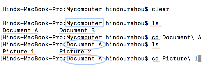
2. Now that I know how to locate my code and how to use the terminal, I need to do 3 things as explained by Jonathan- instructor: Add code to Git, commit it in Git, and push it to Git. The three actions will be fulfilled through 3 different commands: git add -A, git commit -m with a brief commentary, and git push origin master. I went back to the GitLab guide to Basic commands.
Computer Aided Design
The simplest yet most informative resource to understand Islamic geometry is a TedEd lesson by my role model Eric Broug.
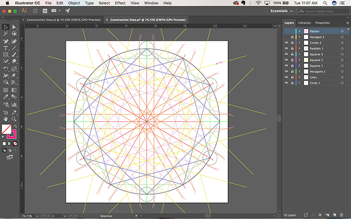
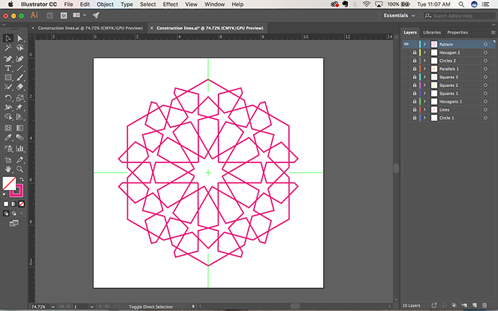
Once I got the basics down I decided to start with building the grid of a simple 6 fold shape. I used Sara Khallaf’s tutorial.
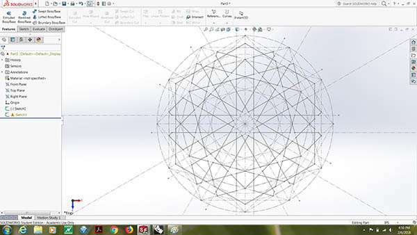
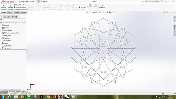
I chose to work with Adobe Illustrator and SolidWorks.
- 2D
Building the Grid
Building the Pattern
- 3D
Building the Grid
Building the Pattern
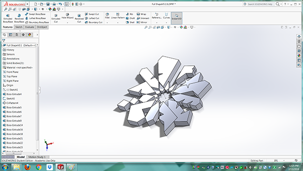
Building the Shape
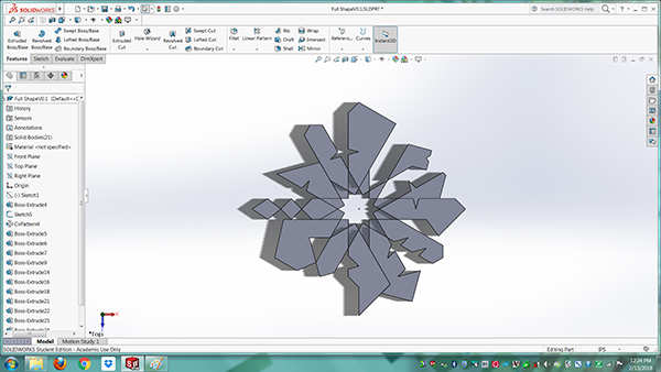
Extrusion
Computer Controlled Cutting
Finally using machines :)
- Vinyl Cutter:
- Laser Cutter
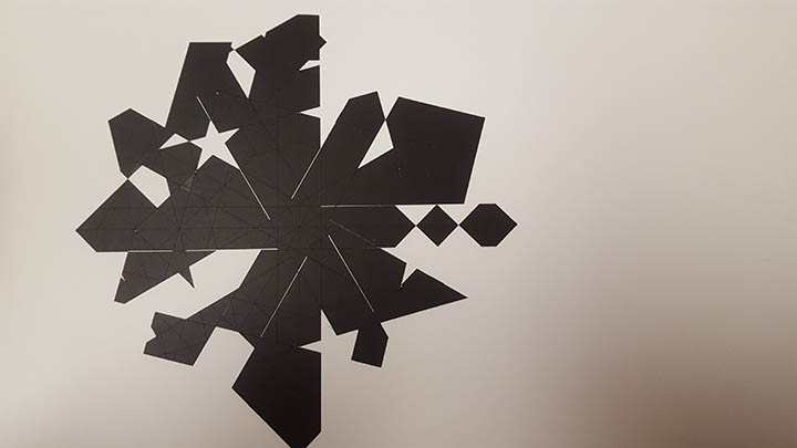
Very un-intimidating machine. Once I had a path, it took Jon (the Lab’s Guru-Hero) 5 minutes to explain the basic function of the machine.There are two things to watch for in Vinyl printing: 1. The Knife 2. The power. Both serve the role of defining the depth and precision of the cut. Depending on your project, you should run a few tests adjusting the two features in order to get your desired outcome. In my case, the pen force was set at +2, and the knife's origin was at it default setting. As for the design, I used the same Illustrator file I worked on last week. Once I made the cut, I used transfer paper to collect the desired shape from the overall grid, then transfered it into a physical workboard
Transfer paper
The small pieces were a nightmare
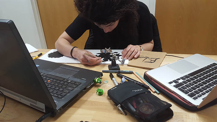
Final design
I stopped working with Solidworks this week and downloaded Fusion 360 tu learn more design tools. Two videos gave me the basic knowledge I needed to make the Press fit kit with parametric design using both variables and constrains.
First is a Fusion 360 video on constrains
Second is a Chaos Core Tech video on variables
Building the Kit
Finished Kit
Mounted Kit
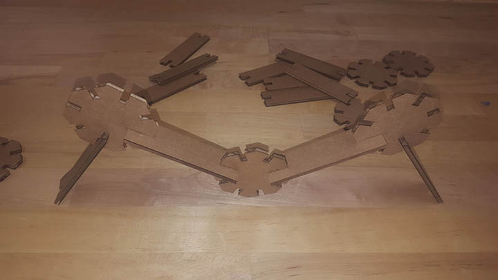
My Speed/Power/frequency was on a scale of 50/50/1500. I would use a different arrangement next time to cause less burns to the cardboard.
Electronics Production
Last time I worked with electronics was in 2009! This +200 min tutorial was a life saver when it comes to remembering the basics with a x1.25 speed. I highly recommend spending the time to go through them before even checking Ali page on the FabISP. Once I got my basics down, I used ShieldMill- Jonathan Ward's app on Github- to print my circuit board. What is super cool about his ShieldMill app is that it has the FabISP ATtiny45 circuit board already designed for you (under projects). It is also two clicks away from generating both the Gcode and the PNG needed to use your local Roland Mill. The process is as follows:
- Select the ATtiny45 project from the projects drop down list
- Select Clear all, 1/32" tool path, and 1/64" tool path.
- Select your printer - the Mill
- Click Make
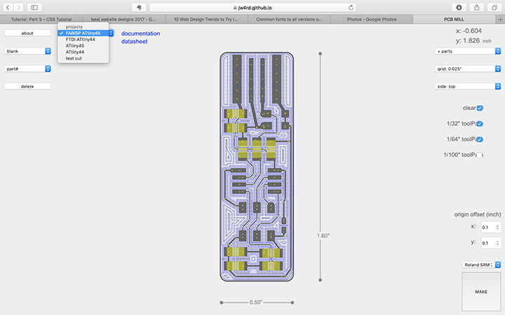 The app will generate two files for you: one for the 1/32" drill bit tool, and one for the 1/64" drill bit tool.
Always start with the largest tool. In this case the 1/32".
Once you placed you Board and mounted your drill bit into the mill, go ahead and find your origins.
Repeat the process with the 1/64" tool. And Voila!
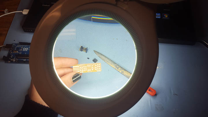 Once printed, time to hit the electronics lab, and figure out the parts.
In this step, both the tutorials I watched and Ali’s article on Demystifying the FabISP, were useful background resources to have. However, it still took Jonathan’s assistance to understand my board.
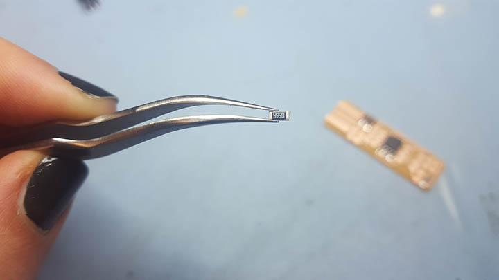 PS: Juan and I used the ShieldMill for our test cuts as well. It is hard to get anything bellow .005 it turns out.
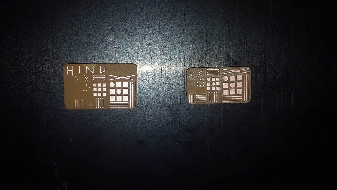 After getting a grasp of what was going on, I turned on the soldering iron. I had experience soldering once for a wire project in college adn I loved it. Here is what I learnt:
- Think of a solder as a heat hugger! Wherever heat goes, the solder will hug. So it you heat up too much surface, your solder will spill over the whole surface.
- A tiny amount is enough. It only takes solder a brief contact with your parts for it to stick. So trust the solder.
- Use the magnifying glass as much as you can! I know it can seem to be an obstacle between you and your project at first, but it is worth sticking to it. It helps your poster, prevents breathing the fumes, and saves your eyesight.
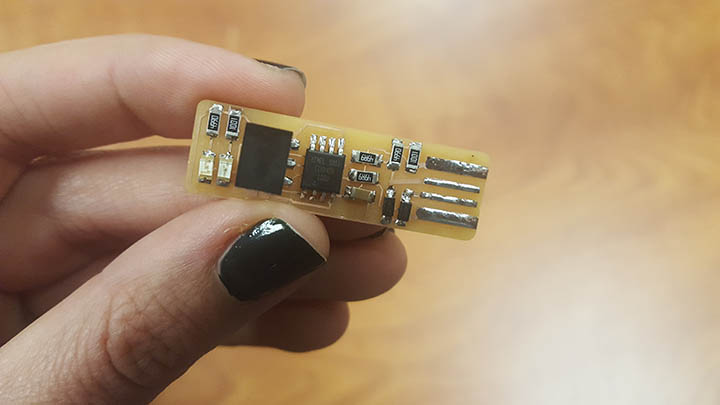
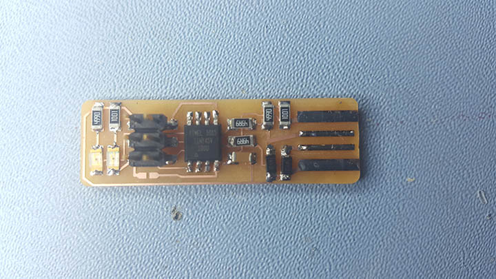 At this point, my understanding of the board is shallow. I bet it’ll be a steep learning curve in about a week.
3D Printing and Scanning
Under consruction!!
Electronics Design
Assignment: Redraw the Echo Hello-World board, add a button and LED (with current-limiting resistor). Double check the design rules, make and test it.
Academy objectives:
1. Select and Learn software for circuit board design
2. Demonstrate workflows used in circuit board design
Personal Objectives:
1. Understand circuits, parts, voltage, and connections so as to be able to read and design schematics.
2. Learn how to read a Data sheet
3. Make a new schematic to the FTDI board with an added button, LED, and Resistor.
Process:
Step 1. Understanding integrated circuits and micro controllers.
Since I am new to electronics, I did myself a favor and spent time on watching youtube tutorials about the basics of electronics. The Youtube channel that I found to be most helpful for someone who has no idea what an integrated circuit is, is CodeNMore.
It is important to understand the basics of an integrated circuit before we jump into micro controllers, because a MC is an advanced version of a simple integrated circuit. Understanding an integrated circuit also helps you read the MC’s Datasheet without feeling too lost.
The manufacturer's description of the ATtiny44 is:
The high-performance, low-power Microchip AVR RISC-based CMOS 8-bit microcontroller combines 4KB ISP flash memory, 256-Byte EEPROM, 256B SRAM, 12 general purpose I/O lines, 32 general purpose working registers, an 8-bit timer/counter with two PWM channels, a 16-bit timer/counter with two PWM channels, internal and external interrupts, an 8-channel 10-bit A/D converter, a programmable gain stage (1x, 20x) for 12 differential ADC channel pairs, programmable watchdog timer with internal oscillator, a internal calibrated oscillator, and three software selectable power saving modes. By executing powerful instructions in a single clock cycle, the device achieves throughputs approaching 1 MIPS per MHz, balancing power consumption and processing speed.
The Datasheet however, will give you a better insight of HOW the MC fulfills the above description. Compare the drawings in the data sheet and the trace of the MC in the board.
Step 2: Read the Echo hello-world board schematic.
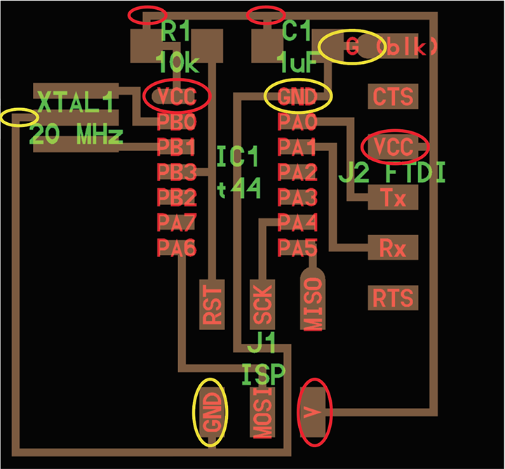
The first information to look for when reading the board is the components’ positions. If you don’t know how a Crystal connects to a circuitboard, you will not be able to recognize or pinpoint it. For an electronics beginner, this could be a real challenge. The picture bellow boxes each of the components of the board.
The board is showing 6 components that we can recognize through the units specified in green.
- XTAL1 - 20 MHz : Crystal/ Oscillator
- R1 - 10k : Resistance
- C1 - 1uF : Capacitor
- IC1 - t44 : Our micro controller IC1 - t44 : Our micro controller
- J1 - ISP : Connection pin (remember the first ISP board we made? This connection pin must connect to that board)
- J2 - FTDI : Another connection pin.
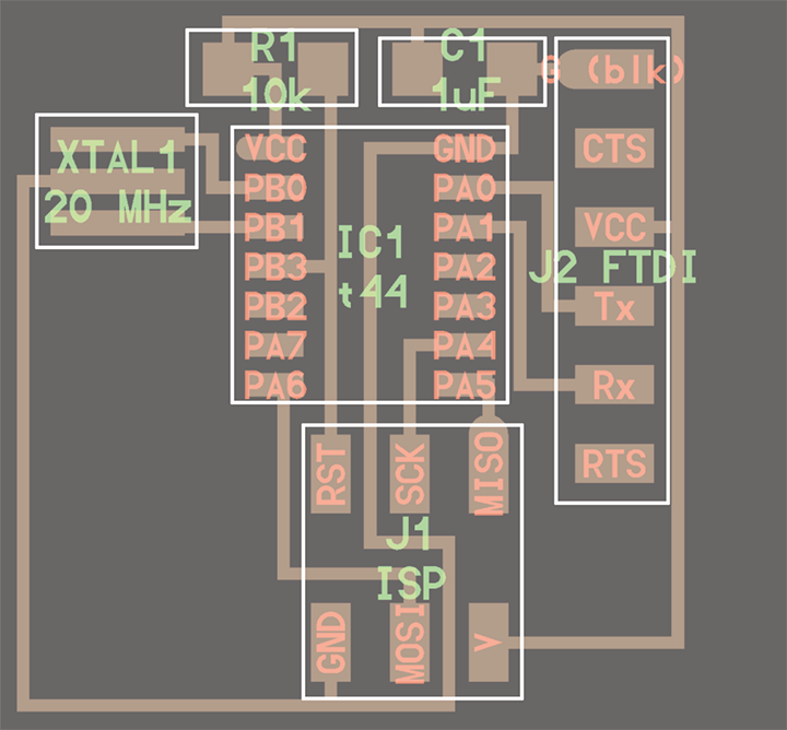
The second information is the flow of current in our board. For this we are looking at two indicators:
- VCC - Voltage at Common Collector, which is a positive electrical connection. Think of it as the source of the current. VCC s circled in red.
- GND- Ground, which can be thought of as the negative or neutral connection there the current exits to. GND is circled in yellow.
Step 3: Identifying the challenge of adding a button, an LED, and a Resistor.
I chose a Green LED and a 4.9 k resistance. That was the easy part. The challenge was in figuring out the button design.
After watching CodeNMore’s tutorials, I know that the button we will use is a double pole single throw (DPST) switch. This means that:
- the button has 4 points of connection in the circuit,
- that it has specific points that internally connect or disconnect according to the button’s status
- That the 2 pairs of points do not connect with one another,
- and that my button should be connected to VCC, GND and to the part I want it to control.
In other words, my button is 1. oriented, and 2. connected to three other board parts.
Step 4: Designing the board.
PThis is the difference between a 1/32" bit and a 1/64" bit

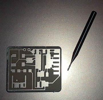
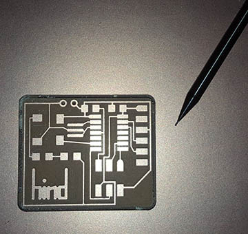
Step 5: Milling and Soldering the board.
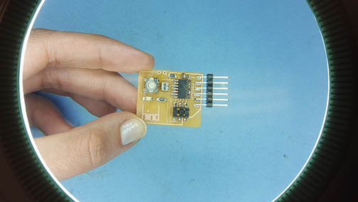
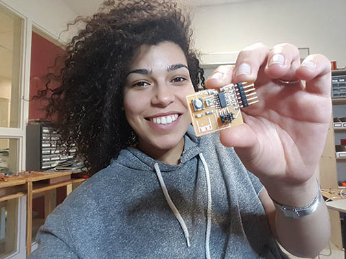
Soldering was as fun as I described it 2 weeks ago in the ISP project. However, the least fun parts were:
- Touching paths of the crystal: When I milled my board, neither the 1/32” or the 1/64” were precise enough to disconnect the lower traces of the Crystal. The GND connection of the Crystal was connected to PB1 of the MC. I thought of redoing my board all together, but I ended up manually disconnecting the copper on the two pads with an exactor knife.
- Pads under the button: I tried to be proactive when designing the button pads so as to make soldering more convenient, but the pads still ended up 1mm wider than expected and underneath the button. I fixed this by 1. putting the solder on the pads, 2. Placing the button where it should be, and 3. Applying heat between the button’s points of connection and the solder.
Embedded programming
Assignment: Read a micro-controller data sheet. Program your board to do something, with as many different programming languages and programming environments as possible.
Academy objectives:
1. Identify relevant information in a micro-controller data sheet.
2. Implement programming protocols.
Personal Objectives:
1. Understand the basics of coding in C.
2. Making LEDs blink in a timely manner.
3. Make a new schematic to the FTDI board with an added button, LED, and Resistor.
Questions:
1. Have you documented what you learned from reading a micro-controller Datasheet?
2. What questions do you have? What would you like to learn more about?
3. Have you programmed your board?
4. Have you included your code?
Process:
Step 1: Understanding the Data Sheet.
In Week 5 and week 7, we have used micro-controllers to populate our boards. During both weeks I spent some time reading through the Datasheet and here is what I learnt:
A micro-controller is an advanced integrated circuit with a complex installation of comparators.
The ATtiny 44 has 14 legs, had more input and output pins and is convenient for running simple programs
It runs by clock cycles
The manufacturer's description of the ATtiny44 is:
The high-performance, low-power Microchip AVR RISC-based CMOS 8-bit microcontroller combines 4KB ISP flash memory, 256-Byte EEPROM, 256B SRAM, 12 general purpose I/O lines, 32 general purpose working registers, an 8-bit timer/counter with two PWM channels, a 16-bit timer/counter with two PWM channels, internal and external interrupts, an 8-channel 10-bit A/D converter, a programmable gain stage (1x, 20x) for 12 differential ADC channel pairs, programmable watchdog timer with internal oscillator, a internal calibrated oscillator, and three software selectable power saving modes. By executing powerful instructions in a single clock cycle, the device achieves throughputs approaching 1 MIPS per MHz, balancing power consumption and processing speed.
The Datasheet however, will give you a better insight of HOW the MC fulfills the above description. Compare the drawings in the data sheet and the trace of the MC in the board.
After reading through the Datasheet, I still have questions about bits and bytes, binary systems, and how do electronics contain memory.
Step 2: Understanding the assignment.
I had a lot of trouble understanding what I had to get done this week. In general I knew I had to program my FTDI board, except I was still unsure about what that meant in terms of process. Since I wasn’t able to imagine what the sequence of steps needed to accomplish the task was, I ended up mis-managing my time. But eventually this is what I gathered:
- Grab an Arduino Uno
- Download Arduino EDI.
- Connect your board and look for Examples to program your board
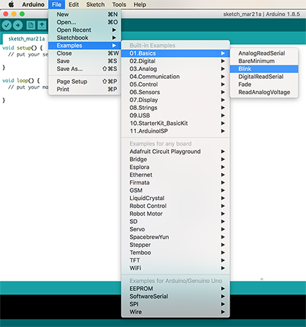
- Define what you want your board to do- in my case I want it to blink the Red LED every second and the Yellow LED every minute.
- Figure out whether your Arduino Uno needs more parts- in which case…
- Grab a Breadboard and the rest of your parts
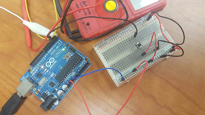
- Connect your Breadboard and your Arduino is different ways by starting with the tutorials available inside the first lines of comments in your example code.
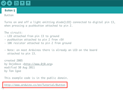
- Experiment with the relevant example to your project and build the closest code to what you want done - in my case it was the Blink example.
- Once you understand your limitations, break down your project into more logical tasks that can be translated into code language - in my case I realized I can’t code for both LEDs under one IF statement.
- Tackle those tasks one by one- you can also reach out to the Arduino community
- Finalize and save your code
- Program your Arduino to be an ISP board then program your FTDI board. by following the instructions in this page