End Effector Design
This week objective is to design and program a machine with our lab colleague.
A machine isan apparatus using mechanical power and having several parts, each with a definite function and together performing a particular task, and with programming it turns into a CNC (Computer Numerical Control) machine.
How did we start?
To start the assignment we needed first to agree as a team on what we want to create, we sit together after the lecture where we did a quick brainstorming and listed all the ideas. Several ideas were suggested.. like:
- Solar cell seeker.
- DIY candy machine
- Coffee art machine.
- Sand Art Machine.
- CNC Plotter
- Foam Cutter
Lastly, we've faced different merits and demerits to each machine, but at the end we decided to go with the CNC plotter option If you wonder why the CNC plotter (Group Project Link)
Overview project:
If you want to see an overview of the entire team about work collectively.
Please check the group project page.
My contribution:
Design:
I designed the end effector of the machine after agreeing on that with my collegues.
I used SolidWorks to design the end effector parts.
Basically, I only used 2 commands to draw the entrie part.


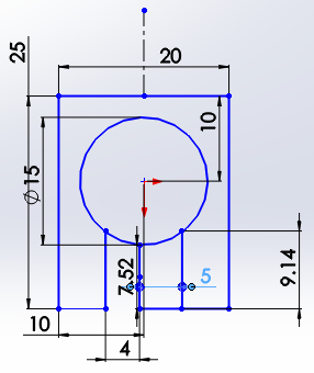
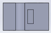
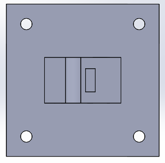
- I started by making simple frame to hold my (15mm) diameter pen:
- I made a slot to put a nut in the frame that will be connected later on with a screw to tighten the part on the pen:
- I drew a back base with holes for screws to be fixed that was supposed to be connected with Ibrahim my coleague part (The one responsible for mechanism designing)
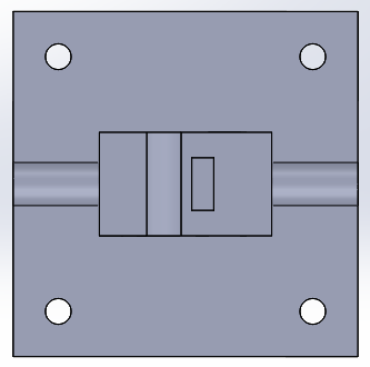
- Then I added a part that will fix the pen even more (with rubber bands):
- at the same step I added a hole for the screw to align with slot made in step 2:
- This step was a refinement to the screw area to make sure they're totally immersed into the part for the neatness of the design purpose.
- This step ensures that the rubber bands will have a slot to rest into the rounded part I drew in step 3 and increase the surface friction area.
- However I needed to add slots for nuts to the screw drew in step 3 so I drew 2 slots for extra strength.
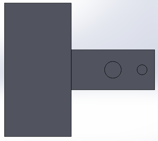
- This how the part looked like at the end.
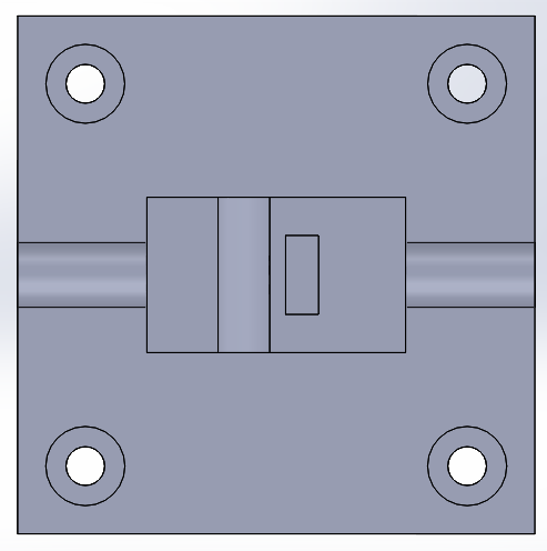
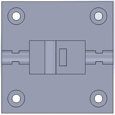
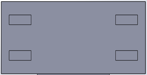

.png)
Output printing:
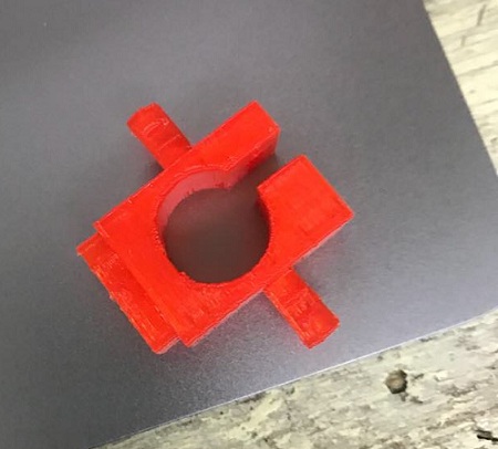
I printed the part at first without the big block addition at step 3 at first to test the fitting concept.
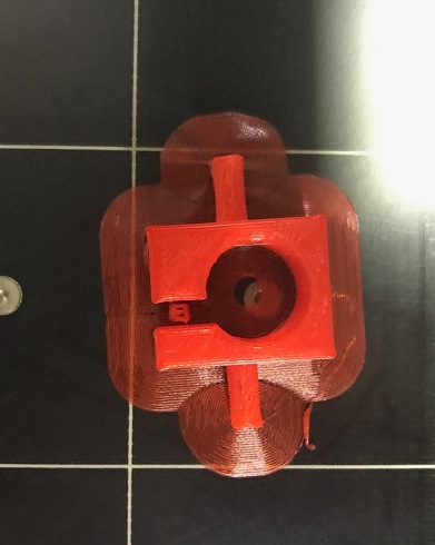
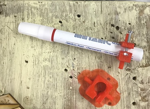
Second print was my part modified by my colleague Khaled and you'll find the details on the
Group project assignment.
