Electronics Production
01
Asigment
Group Assignment
Characterize the specifications of your PCB production processIndividual Assignment:
Make an in-circuit programmer by milling the PCB
Resource
Software
Group Asignment
02
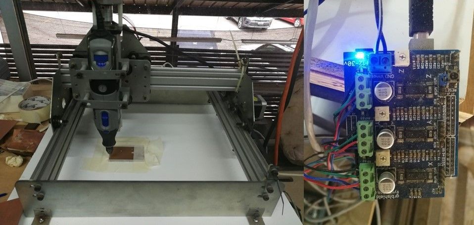
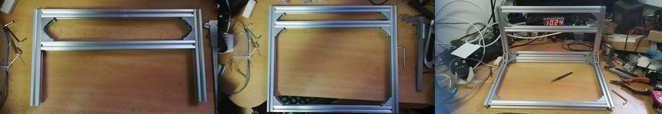
Before continuing with the group assignment. in the fablab they had the cnc milling in repair and update. since the machine was very old and the electronic system was very dirty and rusty which a young man could not fix at all since it only moved the axes of the machine but not the spindle. I offered to fix it, the first problem was that the spindle did not turn on. Second they had two power source separately and exposed outdoors. they also had a card where they are responsible for adjusting the velocity of the spindle.
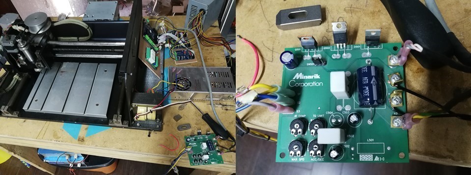
After carefully reading the specifications of the electronic cards they had, I was able to place a single 24v power source that fed the entire system.
I have also reduced the amount of cables they had and optimized the space to place everything in the housing.
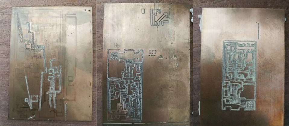
then we use the program of the machine to perform 3 tests.the first one escalated for some strange reason because in the program everything was fine, after making a configurations I was able to make the scale well but the machining quality was not good. and we went back a few days.
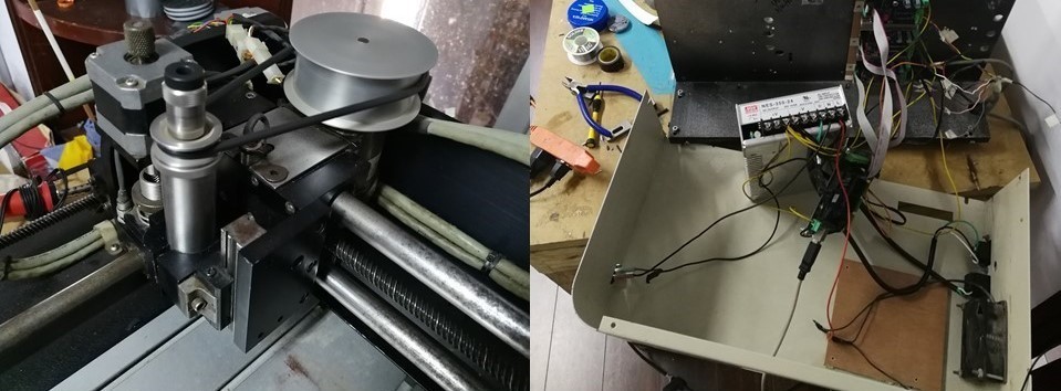
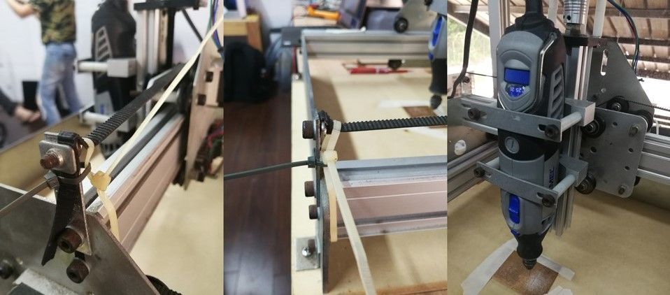
They spent two days where somebody donated an old mini milling (1st generation shapeoko), dirty and very ordinary but it works (not exactly but it works) to fablab, where I had to make a couple of modifications like tensioning the leashes, changing the wooden base to a more rectified, cleaning to the circuit board.
I have adjusted the belt of the axes with zip ties for each axes x, and also I have readjusted the level of the spindle that is a dremel model 4000.
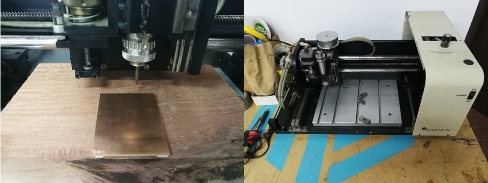
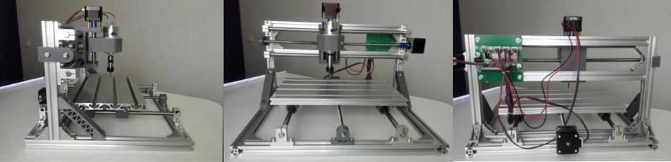
After many problems with the previous machines, I had to buy my own milling machine to be able to carry out my assignments because I was already 3 weeks behind.
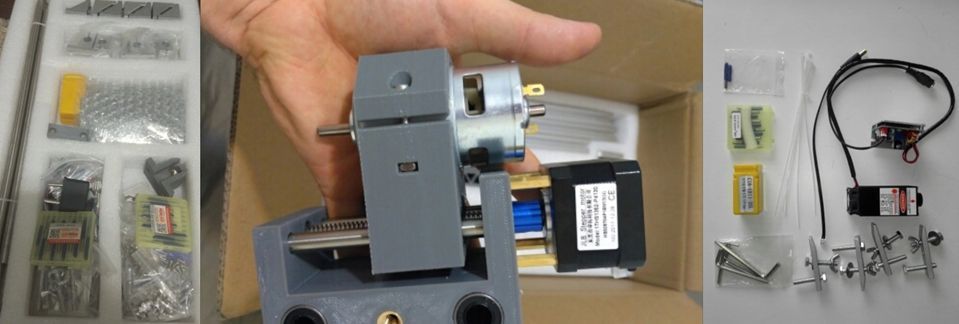
Following the manuals provided by the manufacturer of the machine, I have finished with the assembly and with this machine it is totally more stable when making a cut or engraving.
Individual Assigment
03
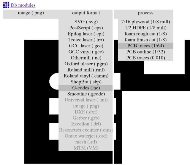
I used the ISP model of fabacademy -Niel which consists of ds monochromatic file frame and circuit design. using the fab module we import the files by individual to general the codes g
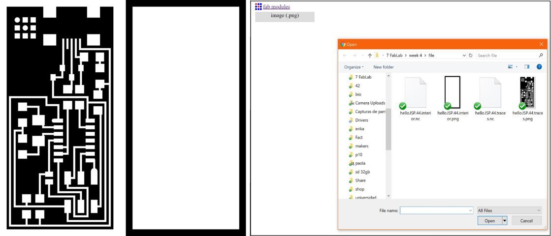
One time importing the file, which we have used the monochromatic circuit file.
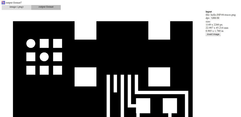
then at the top of the progress bar or process, I have selected G-code cmoo output format >> then in process select PCB traces (1/64).
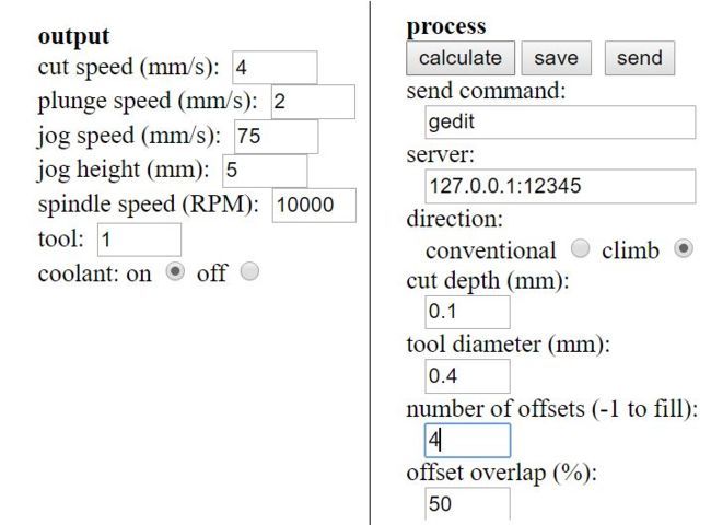
in the right side section shows us options for output and process. where in the output the data for the speed is modified but this time we will not change anything in the same way in the process section only in the scroll number (-1 to fill)
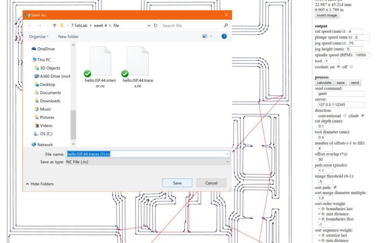
Once the values are placed in the process panel, we click on calculate, then the page will show us a preview of the machining step of the machine with its trayetoria. then to finish we will click on save the one that will save in .nc format.
o perform machining on the machine, use the GRBL CONTROLLER program. where it only has two steps. the first one is to connect to the machine and load the .nc file of fabModule I have also repeated the same previous process for the frame of the circuit to make the cut.
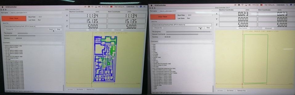
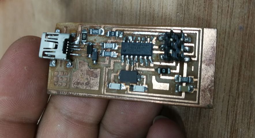
here have some images of the machining process of the machine and one with the final process which can appreciate the psta of the circuit for cad component.
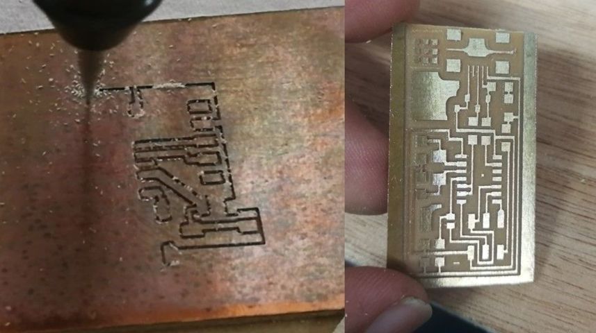
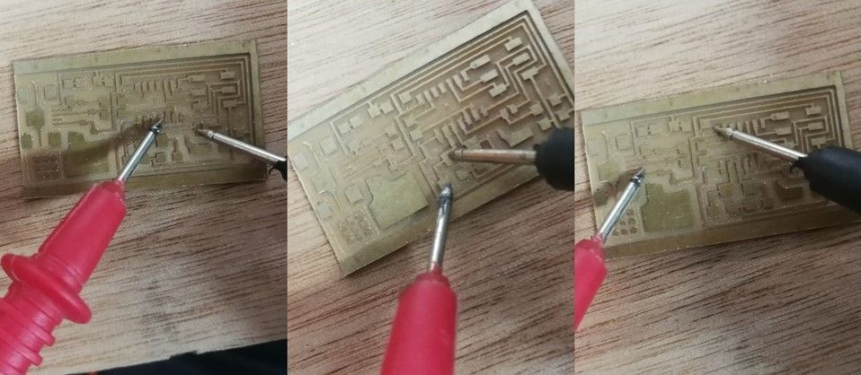
then I used a multimeter to do several tests where I verify the conductivity of each track and thus make sure they are connected.
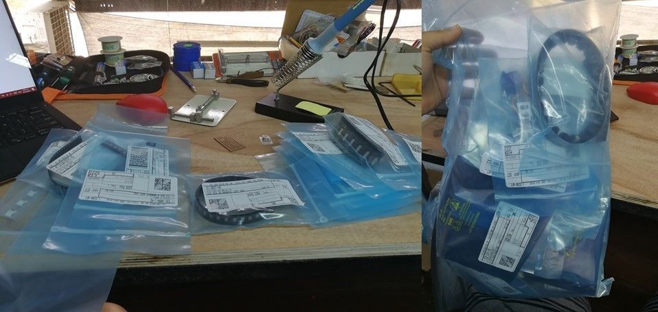
When the circuit is verified, it is ready the work table and look for the components to be tiled to the card. the pieces are in a single bag in order to find the piea and identify what is with its respective values where the list of component is on the web and are:1 attiny 44,1 cap 1uf, 2 cap 10pf, 2 res 100ohm, 1 res 499 ohm, 1 res 1k ohm, 1 res 10k, 6 pins, USB connector, 2 res 0 ohm, 1 crystal 20mhz, 2 zener diode.
If I have all the components, I have fixed the card in a plate holder to make the welding more stable, I used a magnifying glass to see better the welding of the components also use solder and tin that is dedicated to cell repair.
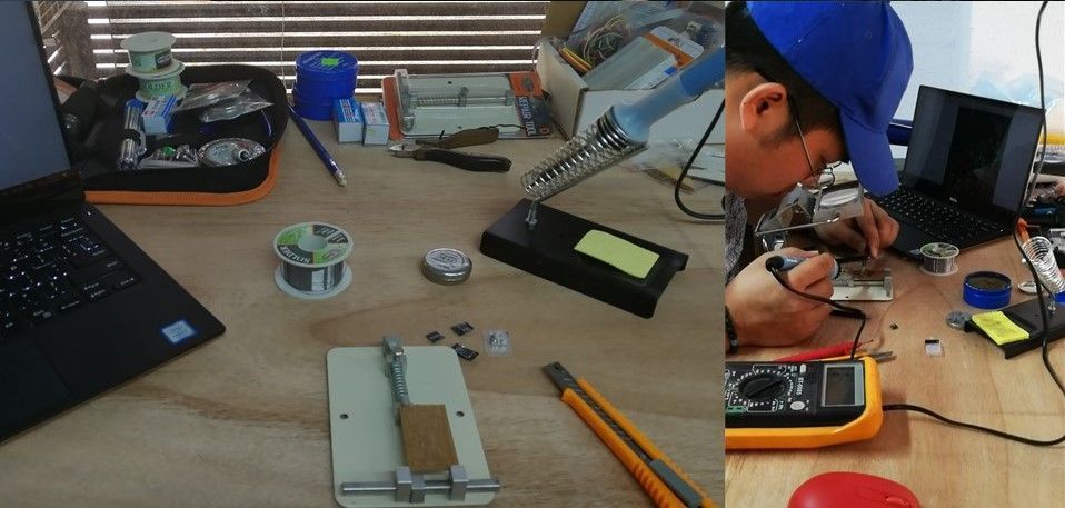
The first component that I have soldered was the attiny, capacitor and the microusb connector, in the process a visturi to make sure that the attiny legs were not connected to each other.
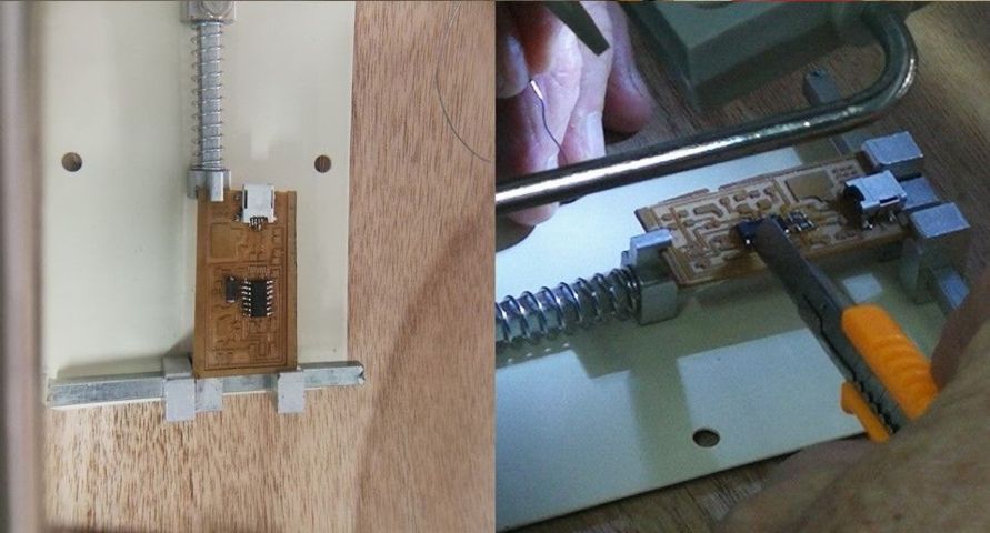
*Then I tried to solder the 6-pin connectors but when trying to weld they damaged the track because i apply to much time heating the tips with the surface and make it a little burn surface and I did not keep trying and started with the other components.
Applying more tin, achieve that the 6 isp pins are welded to the board.
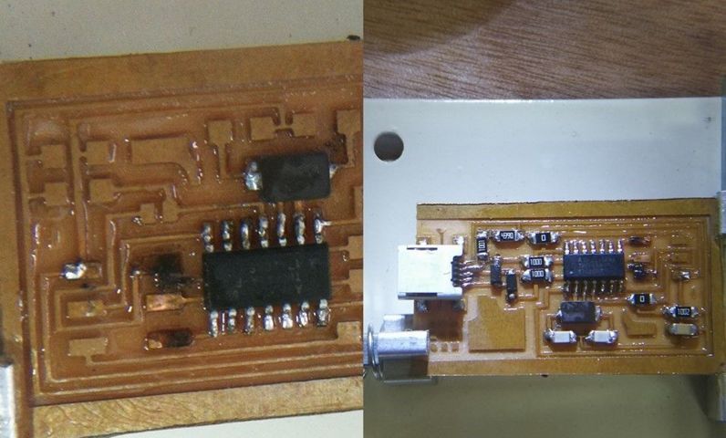
Once the other parts were welded, such as the resistors, LEDs, capacitors and so on, I could weld the 6 pins. I used the multimeter to verify the connectivity of components, also I had to weld a bridge between the 6 pins and the attiny 44.
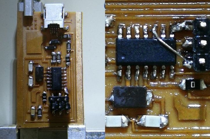
To be able to weld the reset pin to pin # 3 it had to be taken into account of the physical design of the schematic. then I lost the welding of the pins next to the bridge that makes for the serial port conetividad.
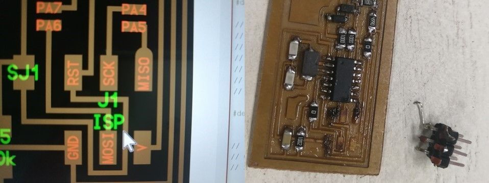
I have made another board, reusing the same component.
For the programming I followed the step of the Fab Tutorial. for the programming of the card and using the method of the arduino isp since by means of mac it has not been achieved besides we do not have the AVRISP MK2.
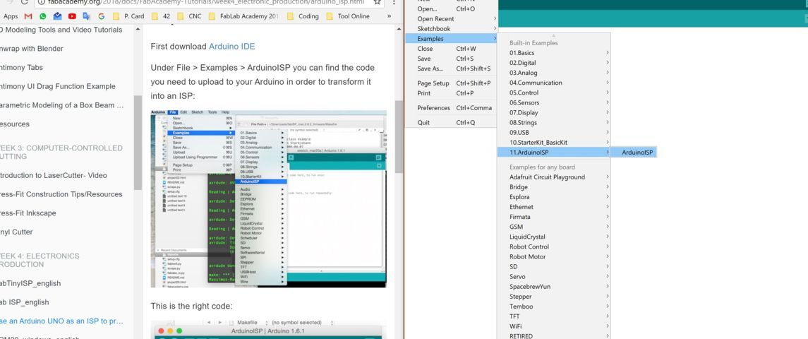
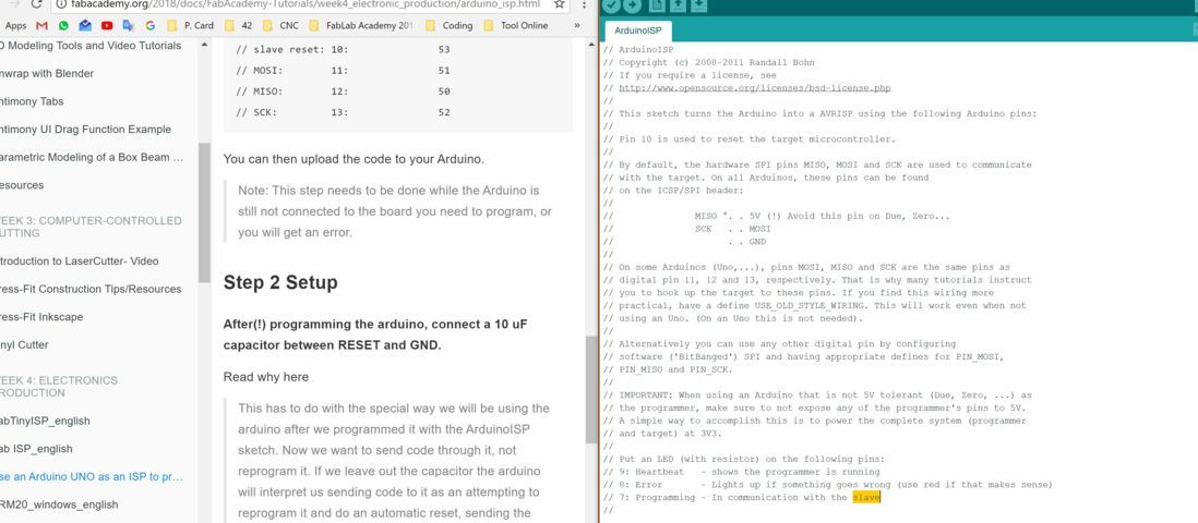
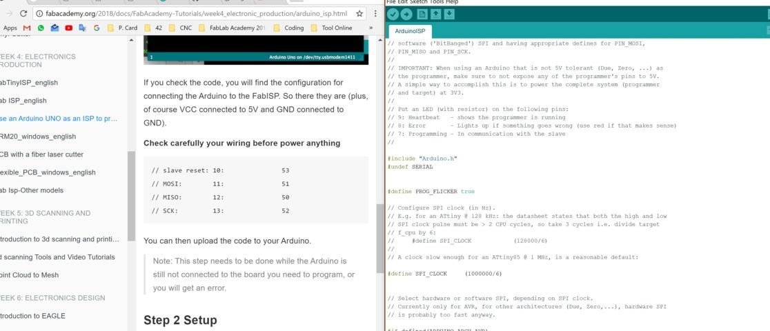
The tutorial tells us that we must change the code that we provide to burn the card and upload the program or finware
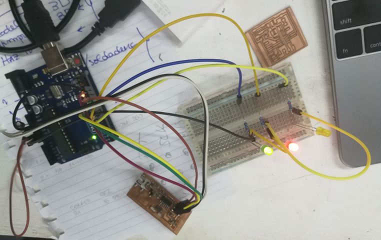
here I have a picture of the connections of the arduino to the ISP to be able to be programmed, i put some led to see the burning board process but dosen't make it. we have found out about the burning of the isp with arduino and apparently using windows is more likely that it does not work and we take it out to use ios - mac
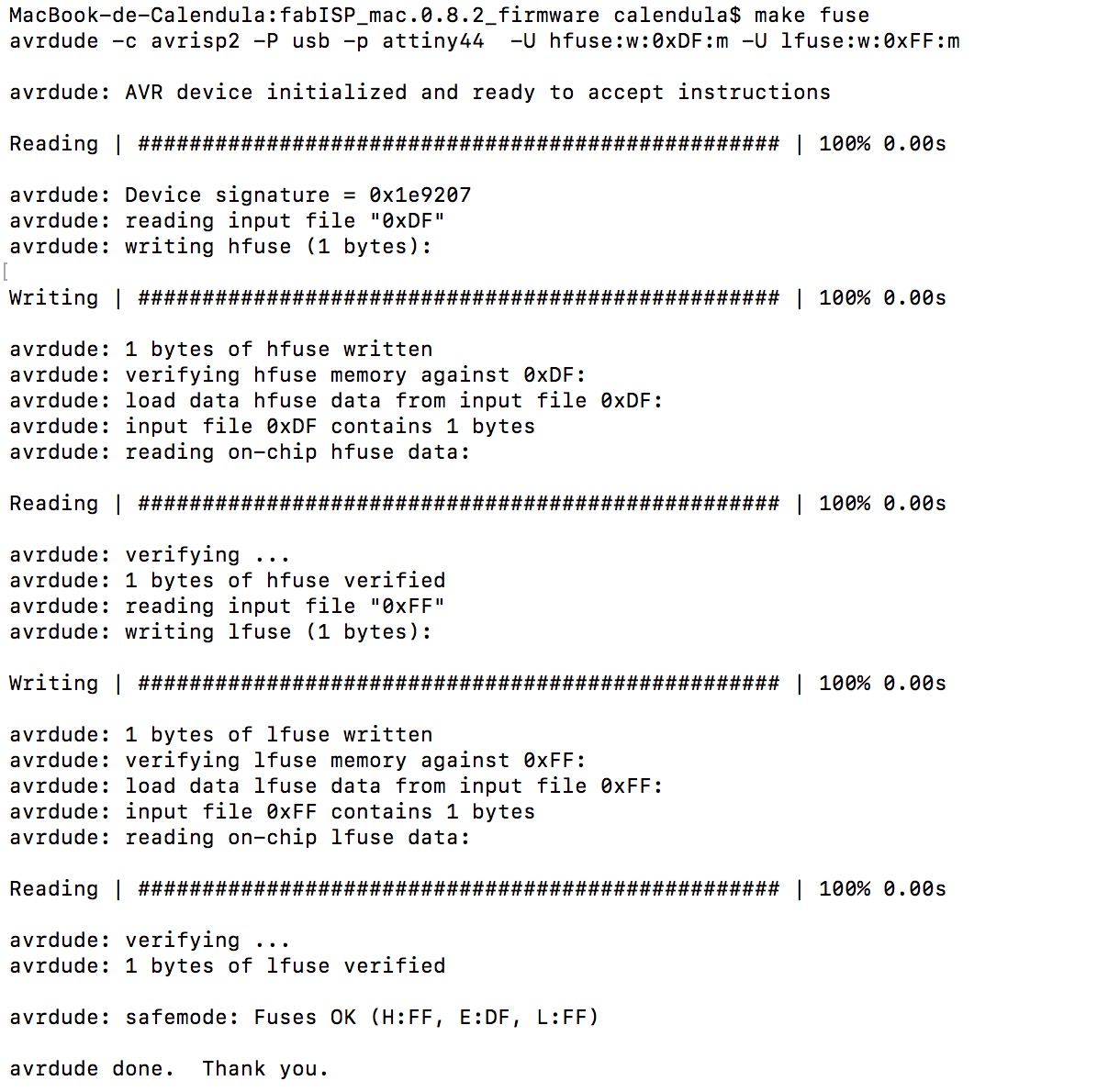
through the Fab Academy Tutorial. we use the IOS option with mac.I have installed the drivers and the makefile. then with the terminal of the mac and with the AVRMKII I verified if the plate is good and if it is ok. then with the command make hex and make fuse, it did not work until I realized that the usb cable was loose.
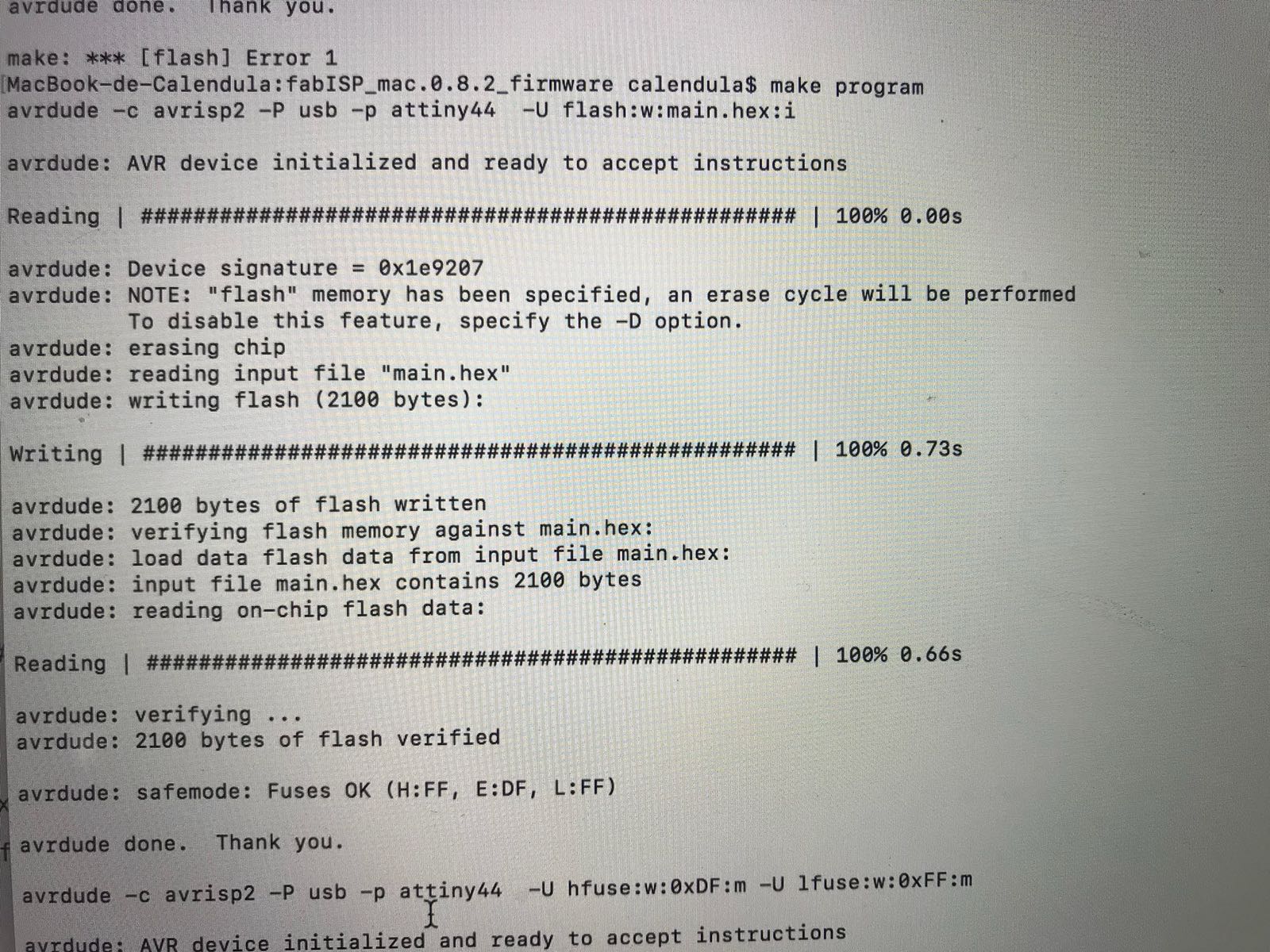
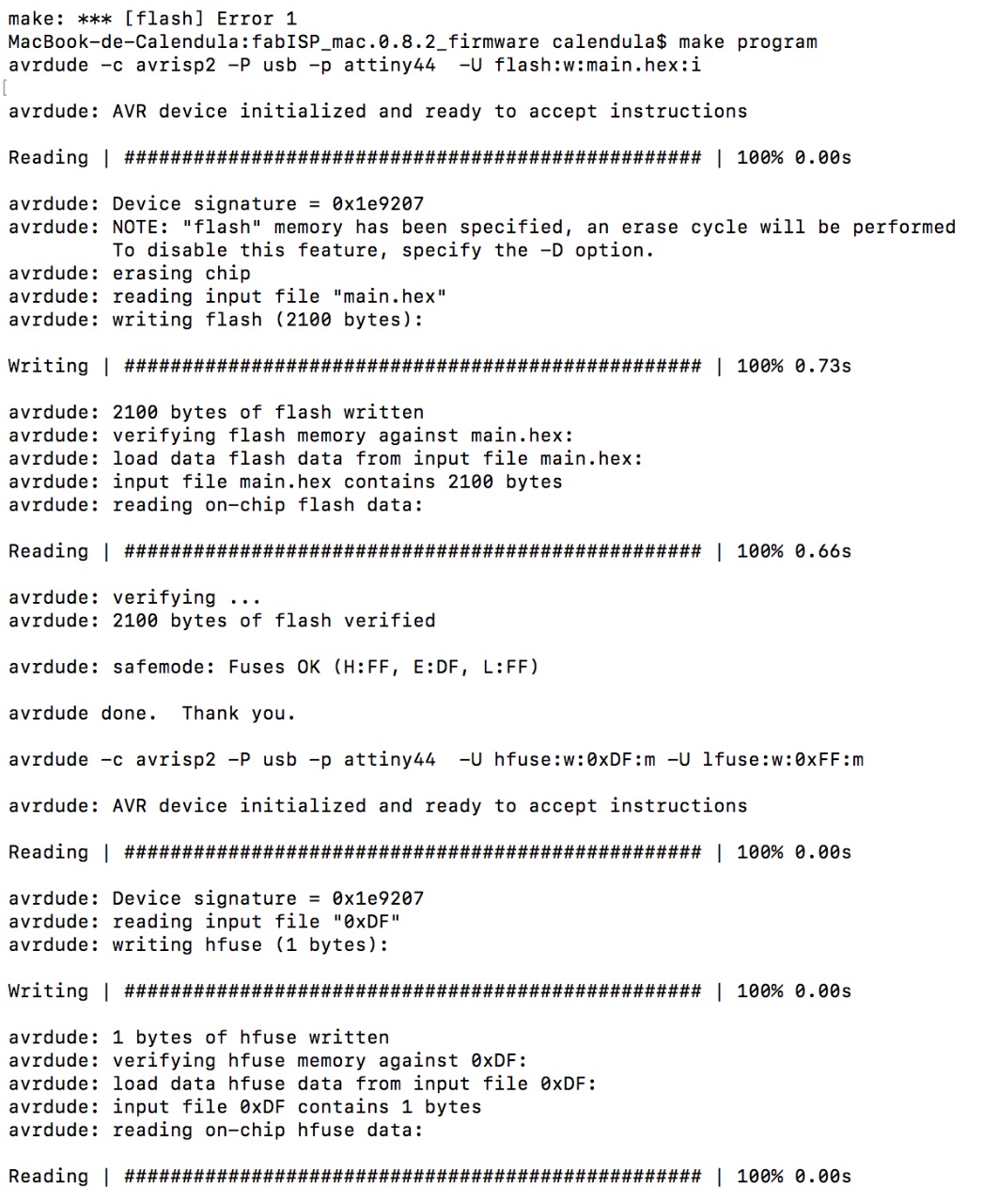
after so much attempt, if I could burn the isp.
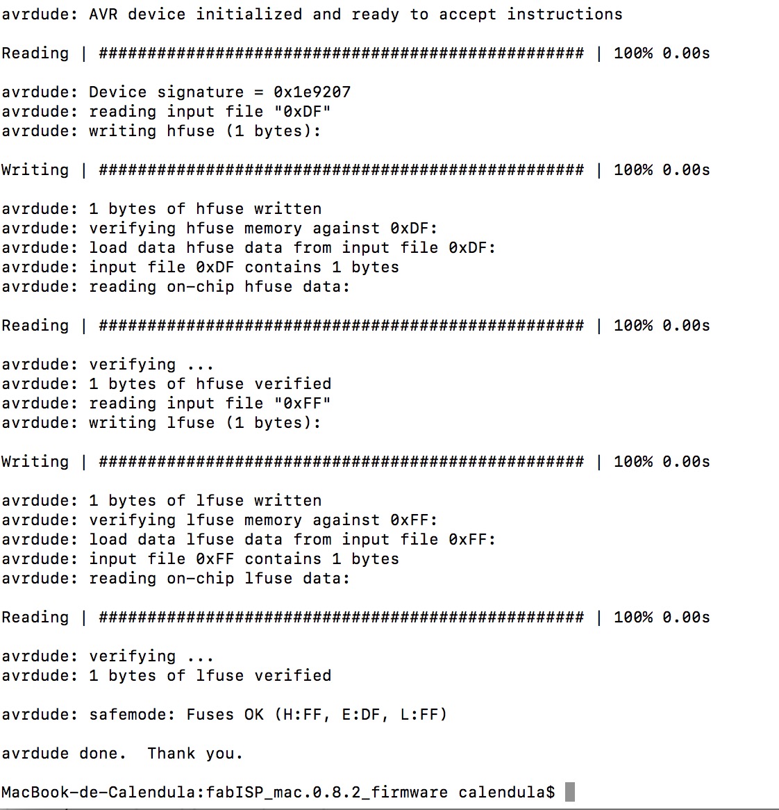
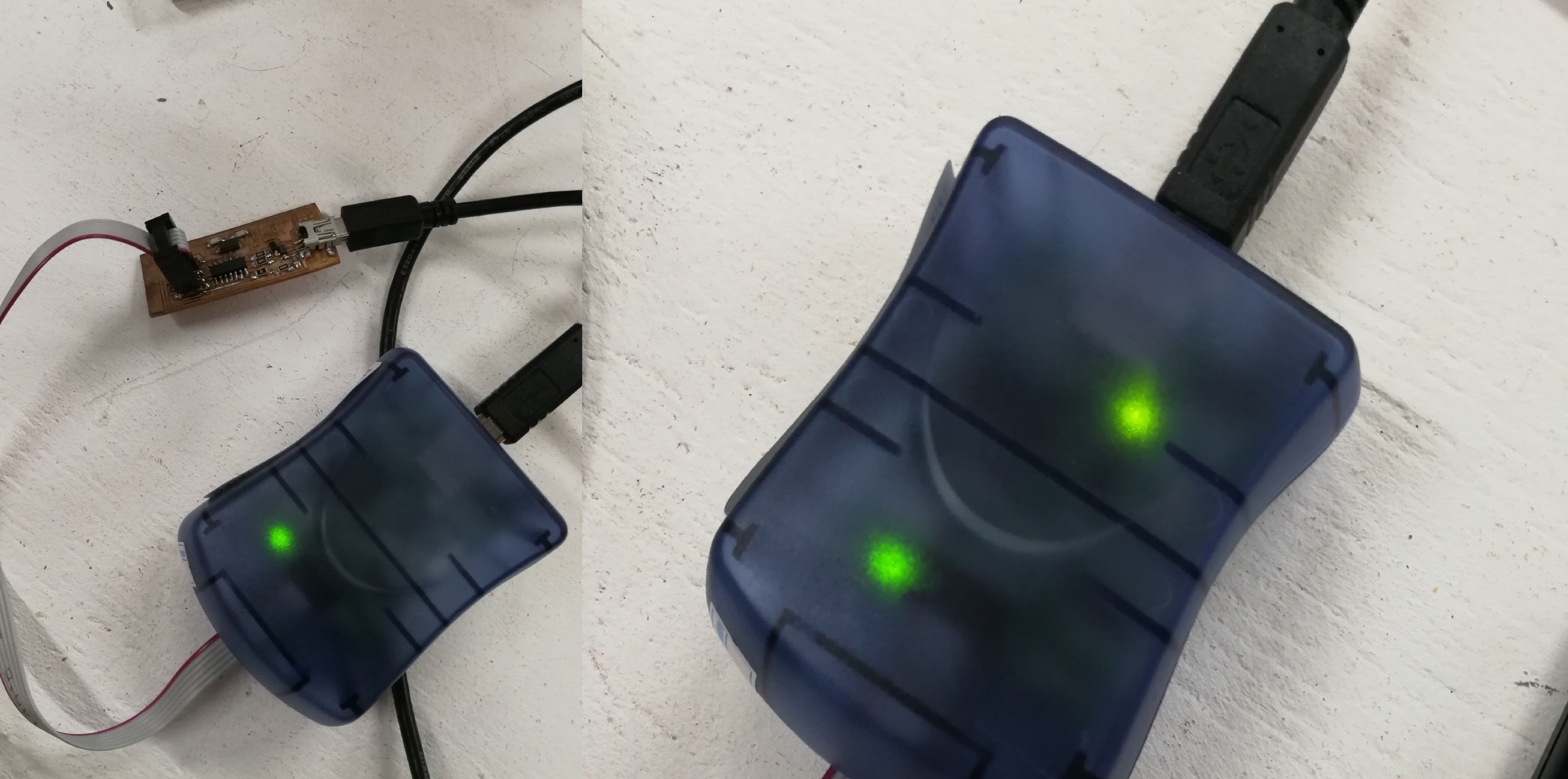
Here there are two photo where the one on the left side is when you check the plate with the avrmkII if you were able to use it. if it had a red color it was not functional and therefore had to make the cut again.
and after having been able to burn the ISO. the AVR MKII indicates with a green light when it was burning.