Computer-Controlled Cutting
01
Asigment
Group Assignment:
Characterize your lasercutter, making test part(s)that vary cutting settings and dimensions.Individual Assignment:
Cut something on the vinylcutter.
Design, lasercut, and document a parametric press-fit construction kit, accounting for the lasercutter kerf, which can be assembled in multiple ways.
Resource
Software
Group Assignment
02
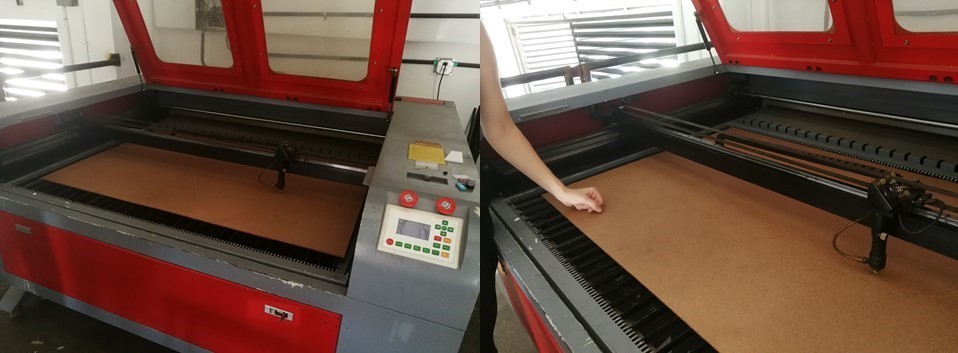
The laser machine is a ghost brand from China (>_<') because is a remake machine with other part.
Characteristic:
- size of the machine: (1.83 m x 1.5 m x 1.20 m).
- area of cut (180 cm x 90 cm).
The machine has 3 buttons to be used. one to start the engine system, two the tray system and three the CO2 tube system.It also uses an additional system for the cooling system for the CO2 tube.the CO2 tube enerates 100w and the power uses 110v.for the maintenance of the rail system it is cleaned and lubricated with a 3 in 1 oil.
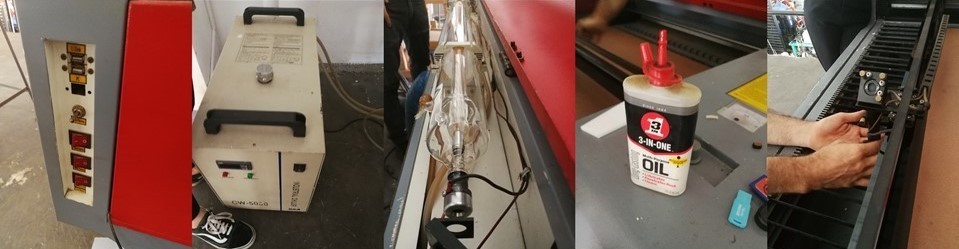
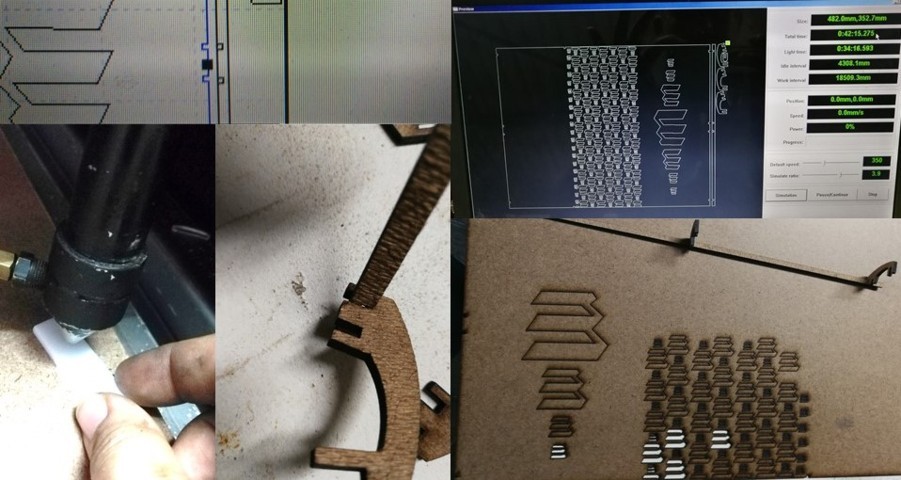
The machine has a system of mirrors to direct the beam that is generated in the CO2 tube to the cutting head where the cutting head has a convex lens that focuses the beam to a finer or smaller point.The convexzo lens must be cleaned with a special alcohol and cleaned every month.We could see the difference of cut in a cardboard which was put on tape and see the final finish.
The machine has a control panel which is independent with the computer. with this you can move the head, raise and lower the tray and set the zero point of origin.the mirror sysema that directs the beam had to be calibrated since the machine was moved in the workshop where each mirror is placed medinate a base with screw.and the program to make the cut is called laserWorV6.
Before performing a cut test. we cut a measurement test for future design in kerf and flex cutting.in the piece of cut that we made to see the percentage or the approximate diameter of corteque that the laser has. where it has a 0.1mm error.
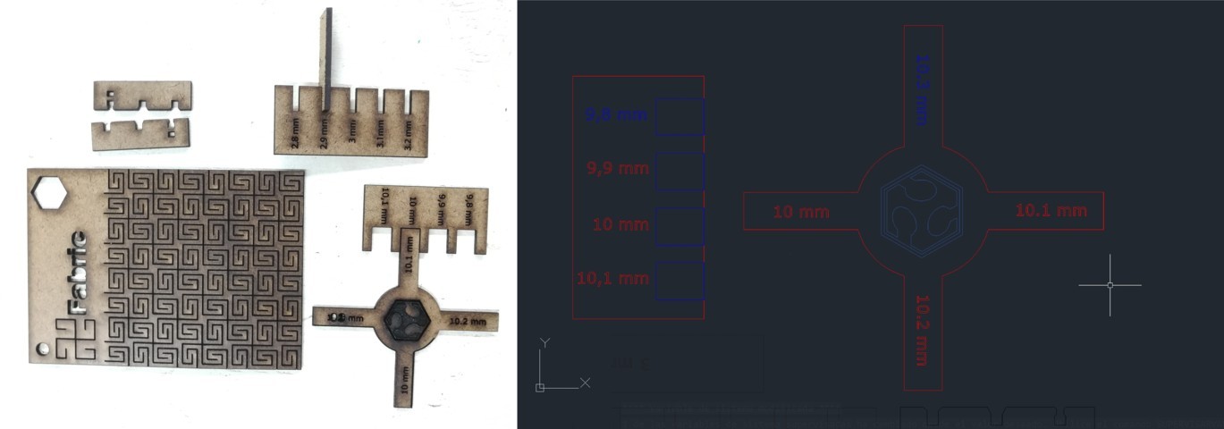 .
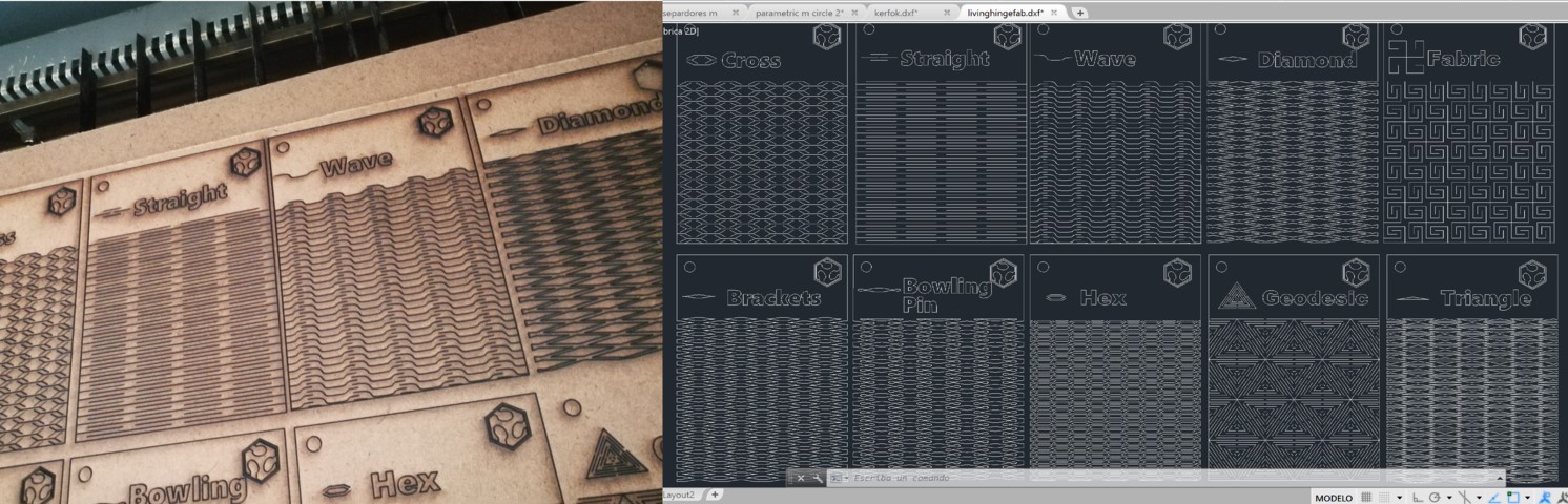
.We cut all the designs available on the page of Fab Acdemy to see which is appropriate to its function or purpose
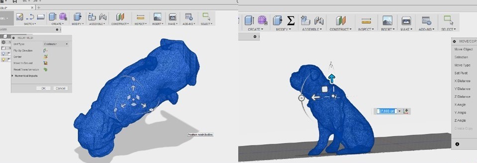
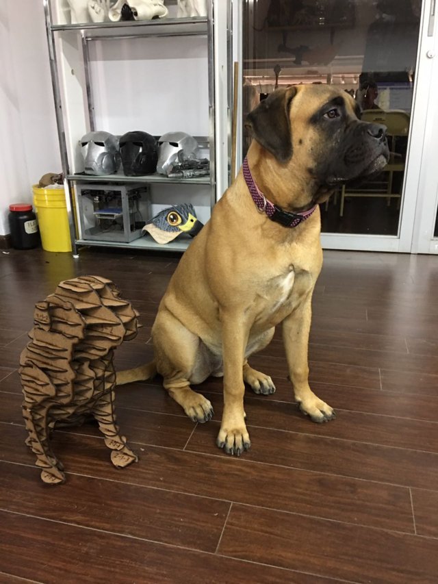
For the test, we had the idea to replicate Peter's pet which is a bull mastiff dog. we find a model in 3d in thingiverse, changing the orientation of the model in fusion 360 since in the slicer it shows in error.because in the slicer program, it was not well appreciated for the final result
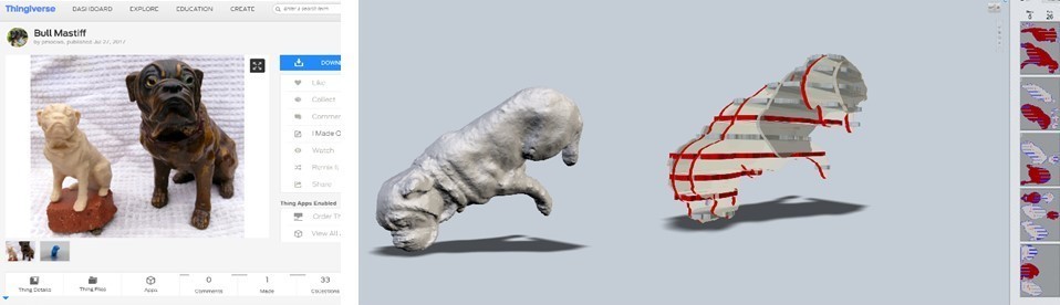
we import the 3d object in fusion 360 to change the meaning of it and we export it as a solid object.
we have used the INTELOCKET SLICE option of the slicer program which shows more style and editing option. As many verticale and horizontal axes that we want, direction or angular sense of all the pieces.
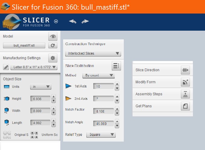
within the program environment, on one side shows all the pieces that can be cut in the laser for each sheet where it is shown in two colors, red means that there is something wrong with this piece and blue is fine.
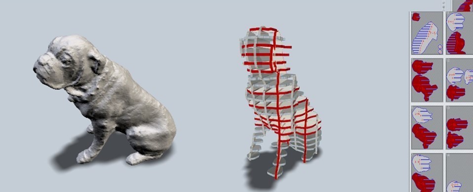
in the final visualization, each level is a piece of cardboard that must be cut and those levels can be moved manually with the mouse where we could move all except for 2. then it is exported in .dxf format. to cut in the program laserworkv6.
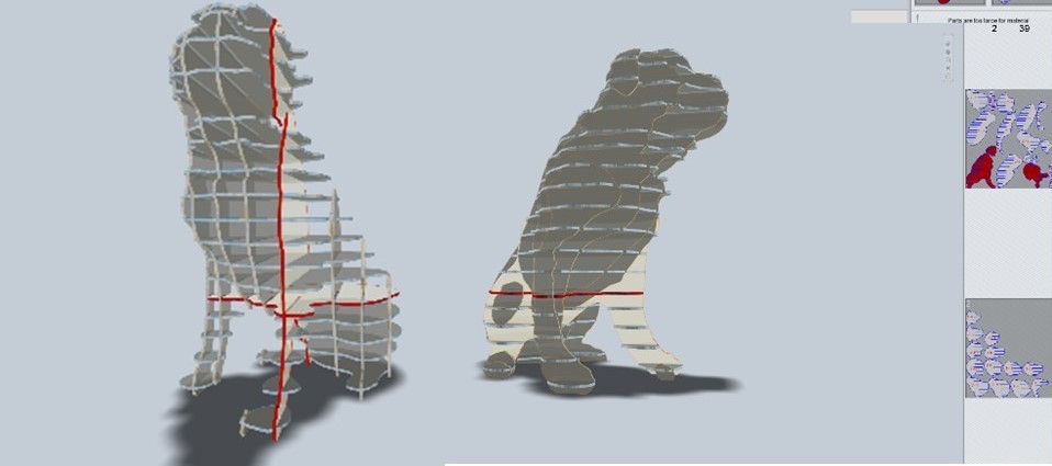
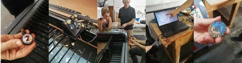
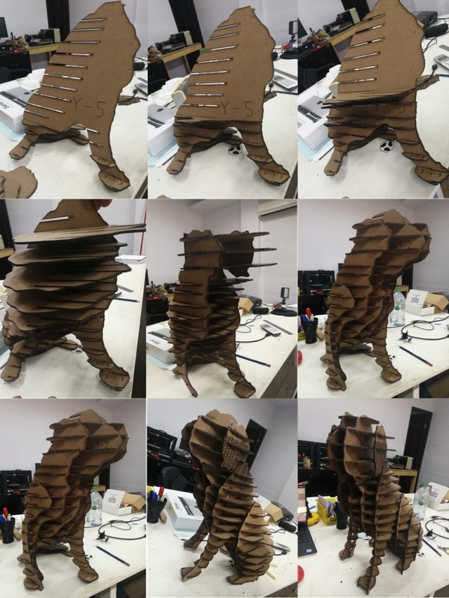
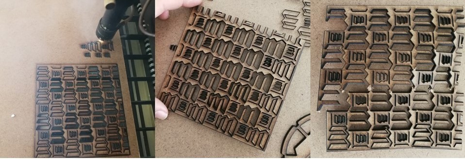
matthew made the cut of each piece to be assembled together with the slicer program.
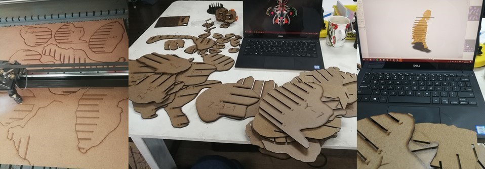
in the program it has a section that says assembly is ayi where it shows step by step the assembly of the house piece and is animated how to do it. where under the program you have an assembly timeline.
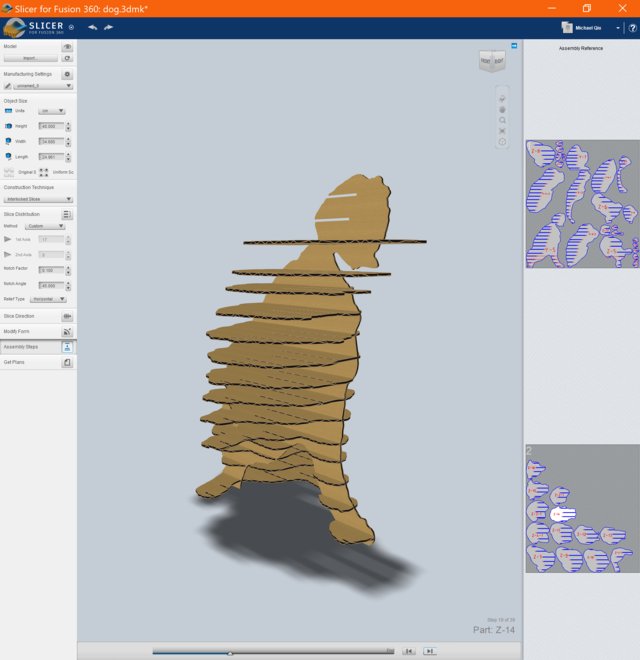
it is here where it shows how each piece is assembled
Individual Assignment
03
- Vinyl Cut
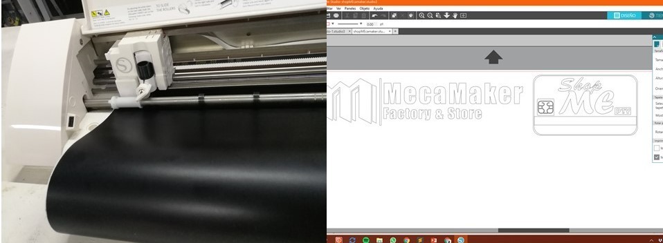
We use a Cameo Silhouette (Old version) to perform the practice and understanding of a vinyl cutting machine. the machine uses a blade where this blade graduates the distance of cutting manually when turning it indicates with number the distance of exit for the cut. and for each material has a distance already predetermined by the manufacturer and software.
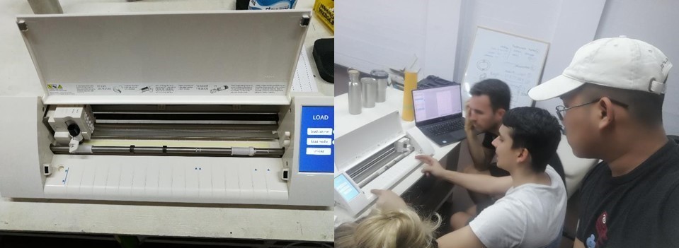
Place the vinyl under a roll and adjust the. the software of the machine is the same company and it is easy to use.just design in Illustrator and export the design to the silhouette program in .dxf format.For the design I used the logo of my two micro companies.
I used a cutter to remove the parts that are not needed.
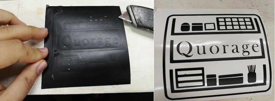
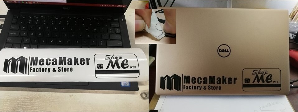
once removed the part that is not wanted. a tape called tape transfer is used. to place the vinyl sticker on the surface you want.
-Laser Cut / Parametric Knerf
I used the parametric kerf in two parts.
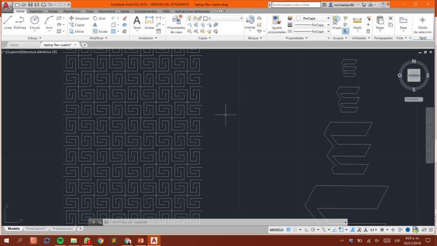
1.laptop flex 2.Super/mini node lamp.1 - laptop flex
Designing a flexible laptop stand where you can fold it in half with your own design. I made a sketch by hand to take the measurements after drawing it in AutoCad.
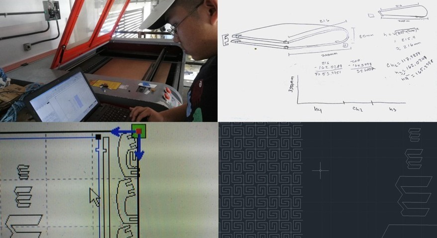
before making the cut in laser machine, the head should be 3mm high of the material to be cut. After a cutting time the machine did not generate the lightning and it had to be canceled. and the problem was that a fuse was burned and replaced.
I decided to cut first the design I had drawn to make it flexible before making the full cut of the laptop stand after finishing the cut using the laser machine, try to bend the design and it broke. so I try to use a parametric design already stipulated. because the machine lost power as I was cutting which I had to do several tests to identify the problem and the trick is that after a cut time put it on hold and wait a bit and continue cutting (repeating this step until the end cut ). why? Apparently the CO2 tube where the beam is generated is very hot and loses power.
as it was not the result that was expected and modified the design to one already stipulated that can be flexible./p>
and this is the final result after so much cutting intendo. for the result the problem that the machine lost power during the cut was to pause the process and wait for the had to cool and then continue cutting.
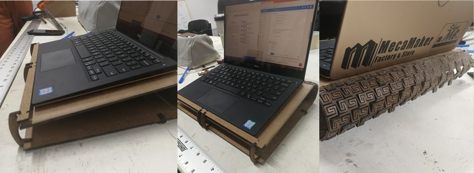
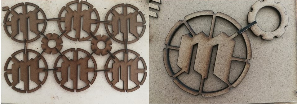
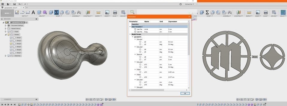
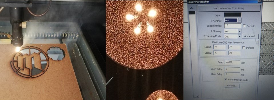
2- 3d parametric designfor this part I use spheroid or circle with connectors to similar a lamp that I saw in a resaurant.I found the way to draw parametrically in the fusion program 360 which is placed the parametric values based on two circular drawings. later I have explained it and made a cut where I could place the mecmaker logo.
After so much attempt, I found the exact cutting property for the material where the power is 77% and the speed is 12 m/s.
my first design was fine but the kerf did not work properly because when you fit two pieces you have a space where it was not fixed and I had to reduce the space of the kerf, increase the pitch also one of the factors that affected is the power of the laser machine because it burned a bit the edges of the pieces and enlarged the space of the kerf. After performing several cutting tests with the speed and power I could find the right one. In spite of that I had to do the pause method and continue.