Input Device
01
Asigment
Group Assignment:
measure the analog levels and digital signals in an input deviceIndividual Assignment:
measure something: add a sensor to a microcontroller board that you have designed and read it
Resource
Software
Group Assignment
02
Individual Assignment
03
For the input assignment I make a keypad. the input does not have a microcontroller or chip I must also perform the fabduino.

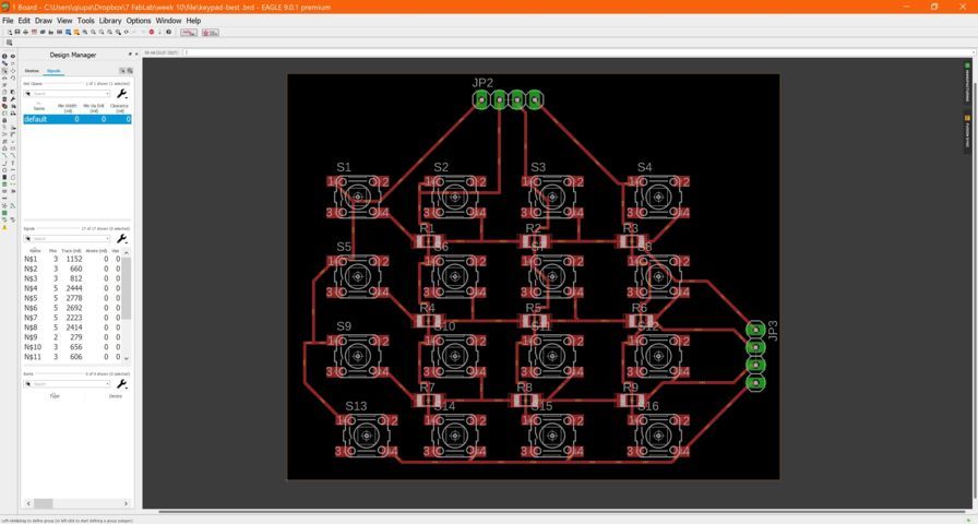
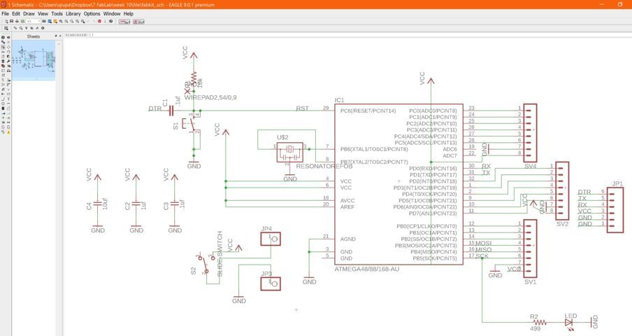
I found this diagram to make the schematic of the circuit in Eagle.

then I have connected all the component in Eagle in row and column.

then fit all the components on the physical card.


Applied the DRC to generate the track of the automatic circuit but they did not go well

After so much attempt I found another diagram as a guide in the schematic.

and again the circuit track was not well generated.

again I have not done anything right because I realized that the column and rows will always be superimposed and I had to find a solution.

After several attempts I was able to generate the tracks well because i put resistance in the row as a jumper.

Then I have divided the connector so that I can general the tracks since I had problem again.

After accommodating the components, the circuit track has been successfully generated.

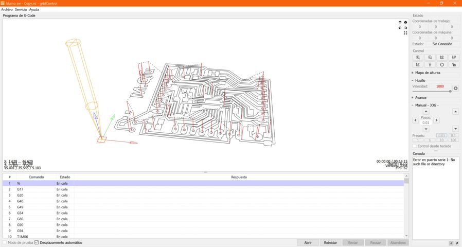
I have made the .NC file with the Fabmodules and I have it in the GRBL CONTROLLER program to make the circuit cut.

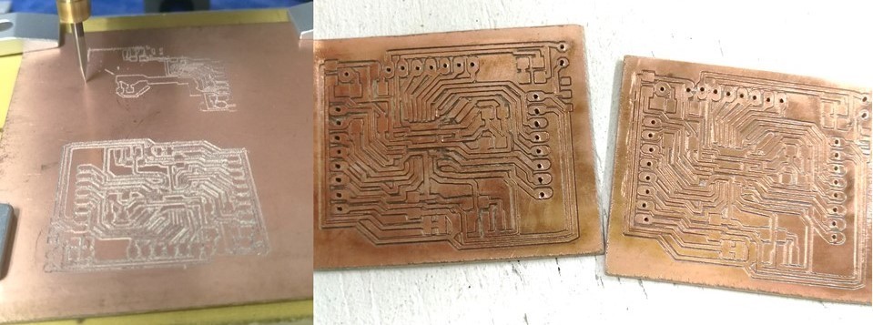
This is where the machine cuts the circuit.

Then I started to solder all components that are the buttons

then I put the card to test but something was wrong because in all the row and column the led was lit which should not.

I realized that the buttons are missing a part by connecting to the ranks of each level and passed a scalpel and solder what was missing.

Then I had to change the schematic in eagle. adding that connection that was missing.

The board has been successfully made to be cut
I have cut the board and here is the comparison of the new and old board.
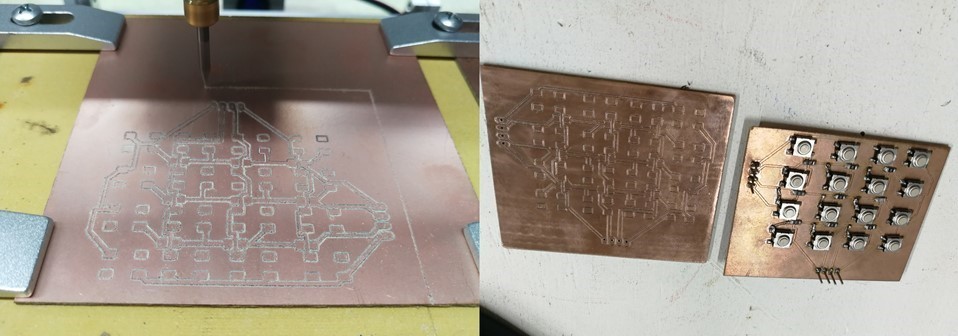
in the FabLab we do not have as much component as to weld new components which I have decided to remove the components of the old plate to the new plate in addition while soldering the components I was testing with the multimeter in a continuity way.

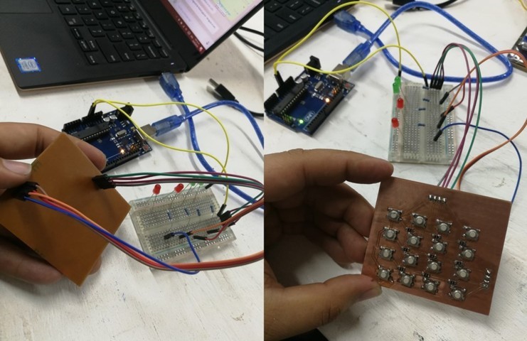
I have already welded all the components on the new board.

I used an arduino as a source to test the buttons.
to make the fabduino, I used the FABKIT 0.3.
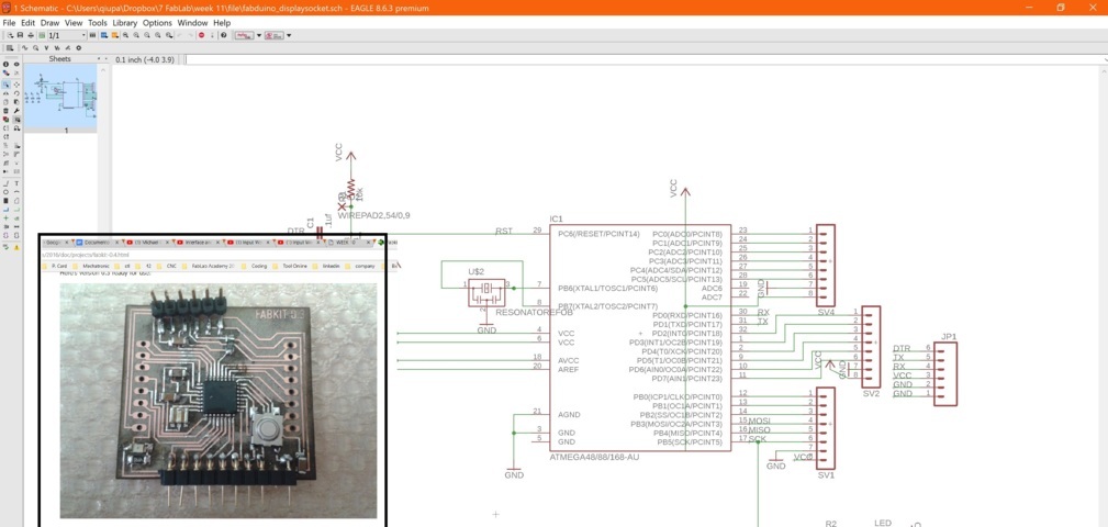
in the schematic I have added a swicht and some pins as a source and the swicht to power off and on.
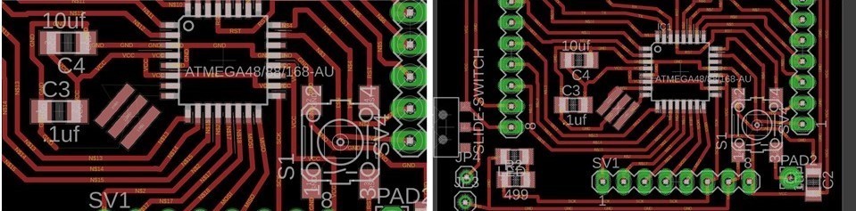
I have accommodated the components to be able to general the track of the board like the fabkit (right).

I have put my initials on the board.

Generating the .NC file in the fabmodules

making the board en GRBL CONTROLLER.
in the process I noticed that the plate went wrong because some clues did not come out divided if not stuck with the other.

Again I made the schematic again but this time a little more spaced so that the track is not so close.

Although I have done it again, the tracks come close to each other, where I have arranged each track by hand.

Then in the fabmodules, I saw that the track went well and I cut it with GRBL CONTROLLER.

I have cut two board for the week input and the week output.
I have tested the track by individual with the multimeter and separated the components to be able to solder.

I have had some problem in the welding, some chips of the chip were stuck but I could fix it.

I have soldered all the board successfully.

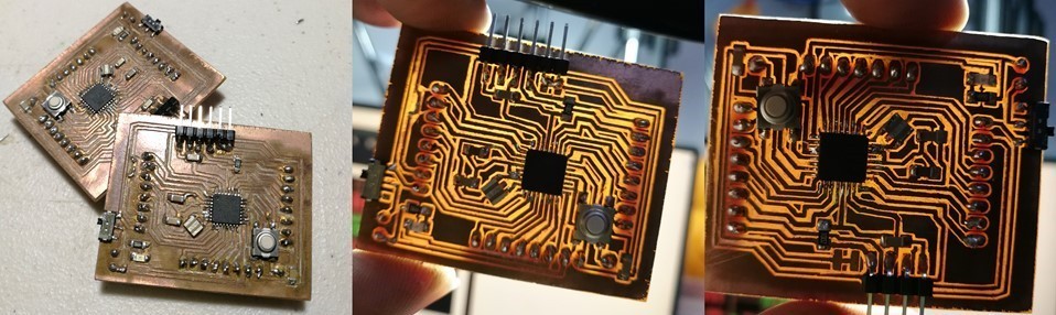
A trick that I found to verify if all the components were well welded to the plate, is about the plates to a lamp and see the track since the light makes the plate appear somewhat translucent.
After having all the plates welded and tested. I have bootloader the board with Arduino IDE. and there are two methods, by serial cable or with an isp.

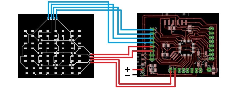
with the fabduino data sheet and how the keypad is built. I have made the connections. to test the keypad.

This is the connection diagram of my plates that I made.
and this is the Arduino code to use the keypad.
