Back to Mejdi_FabAcademy_FollowUp
Week15: Networking and coms
Assignment:
- design and build a wired &/or wireless network connecting at least two processors
- send a message between two projects
Part of my final project.
Making a custom ATmega32U4 PCB
The ATmega32U4 has a USB core. No need for a FTDI chip!
What I want this PCB to do:
-
Output
-
Coms
- USB via mini-USB
- RF via nRF24 module (requires 3.3V => regulator on pcb)
- ISP
Design v1
As usual, I used KiCAD to design my PCB:
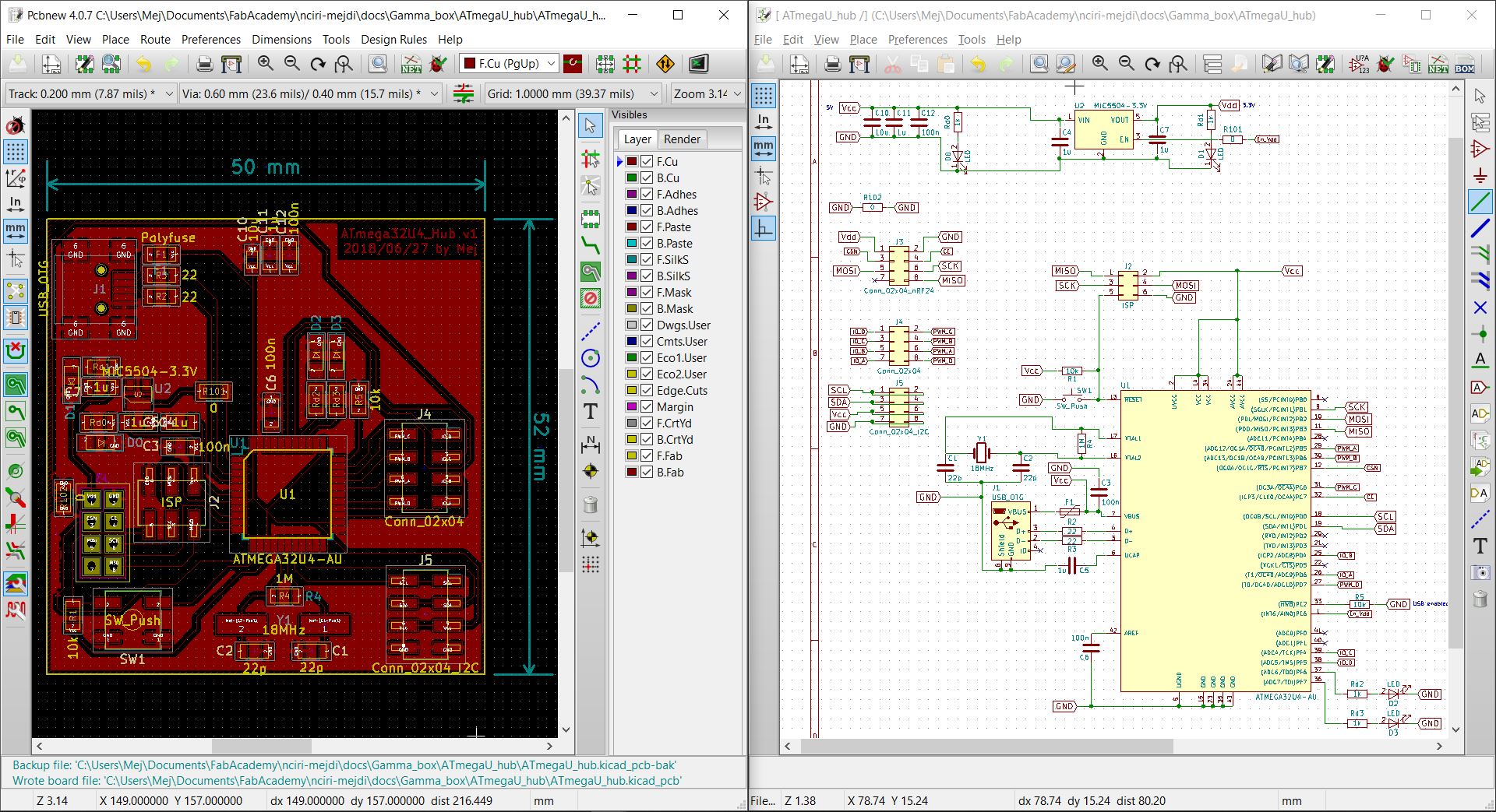
KiCAD project directory is here
The essential fabrication files are the shematics and the svg.
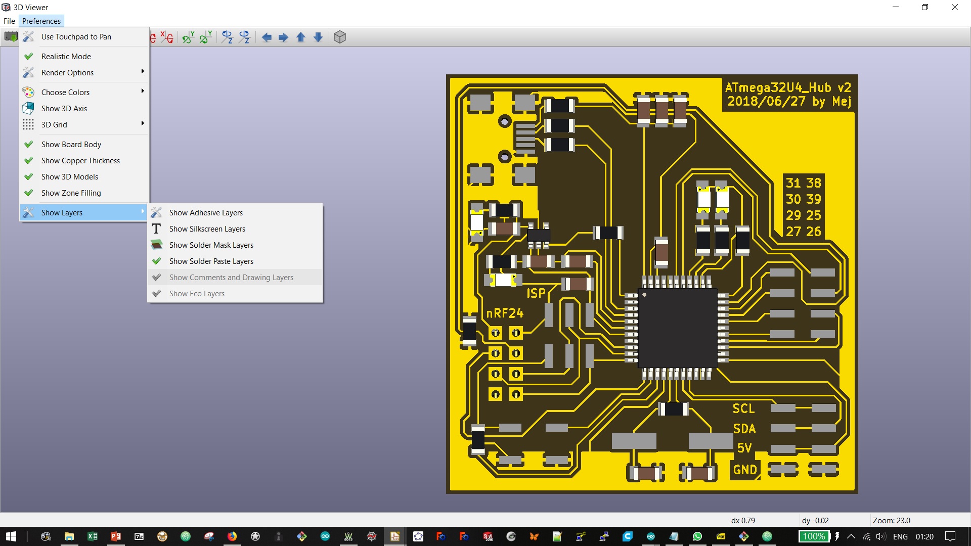
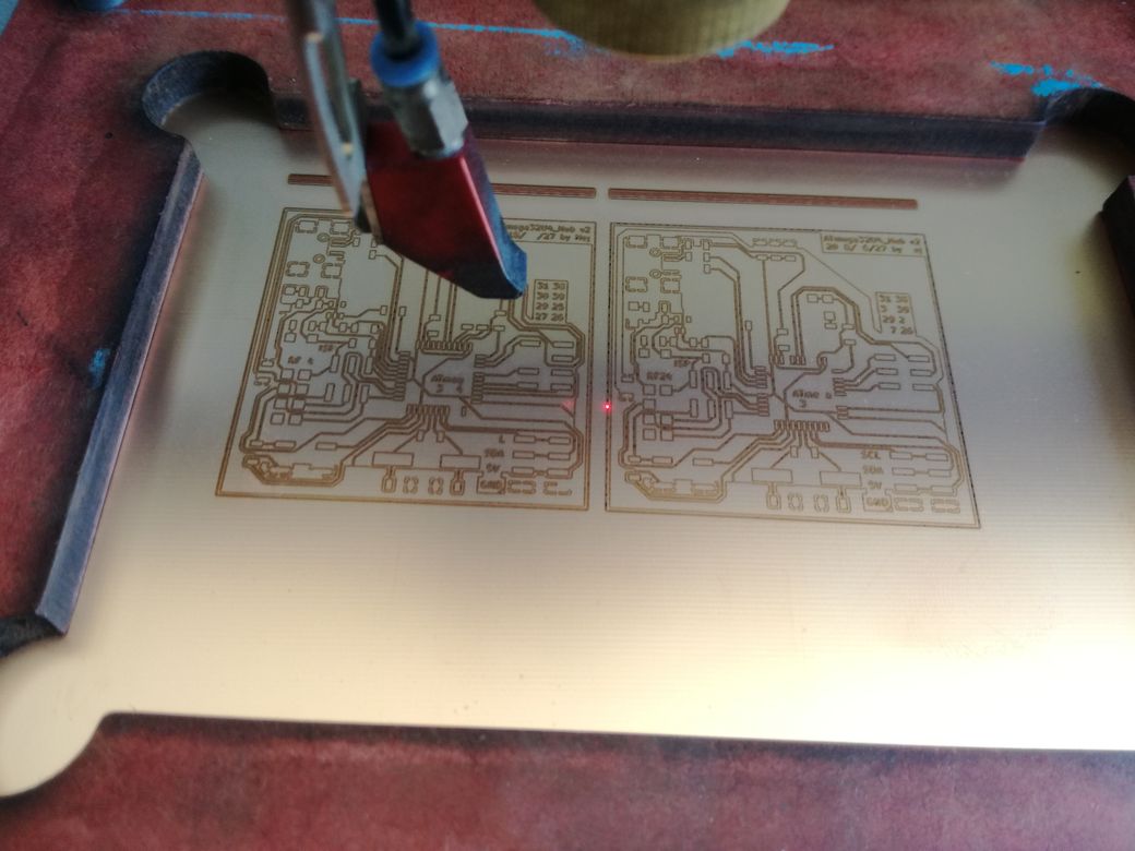
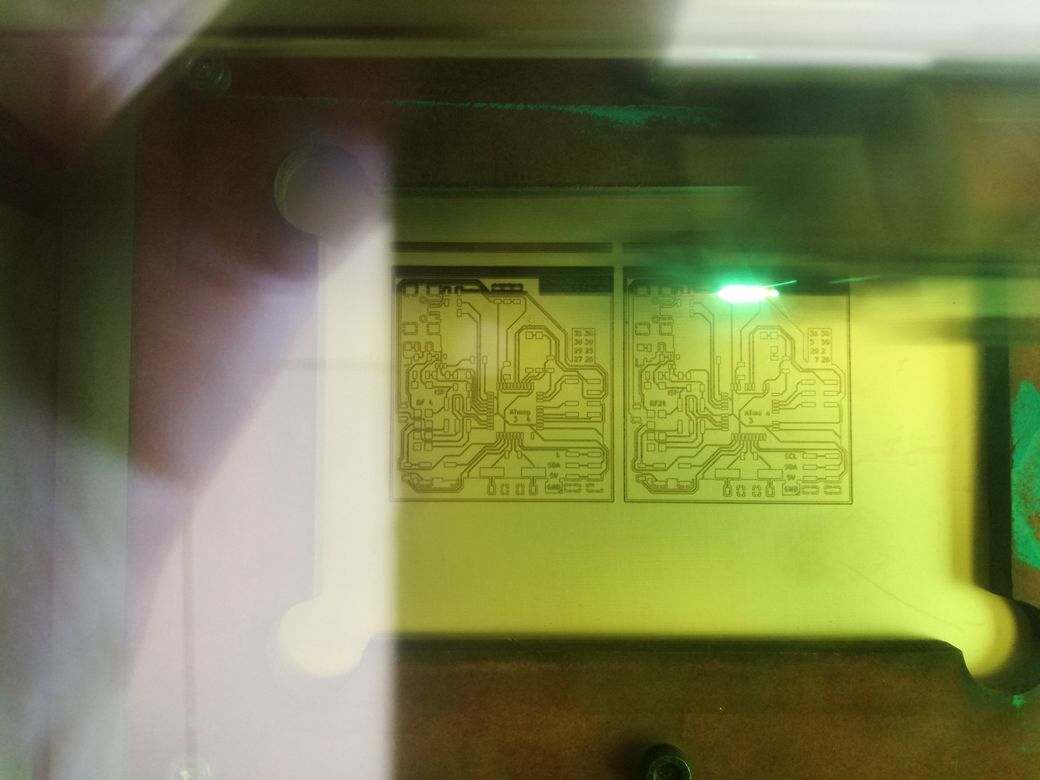
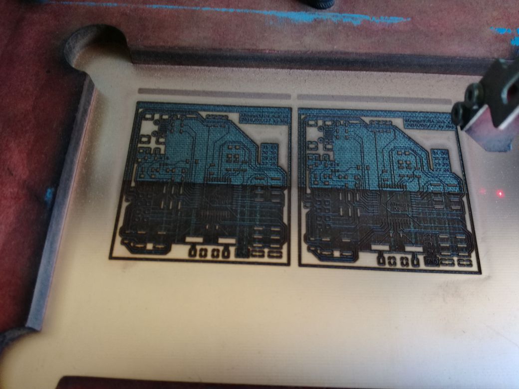
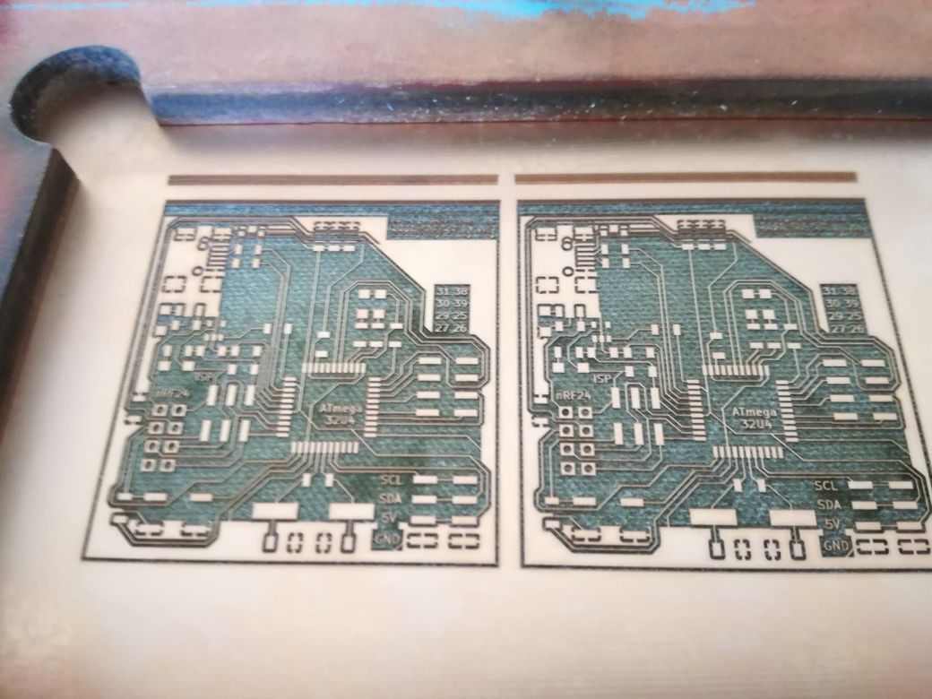
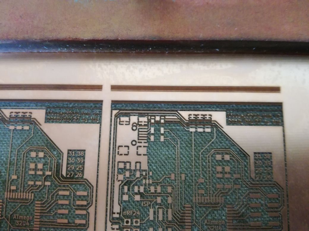
Design v2
A quick print to check the footprints.
Few retakes on PCBnew: more space around crystal, pins anotation, cleaner ground plane.
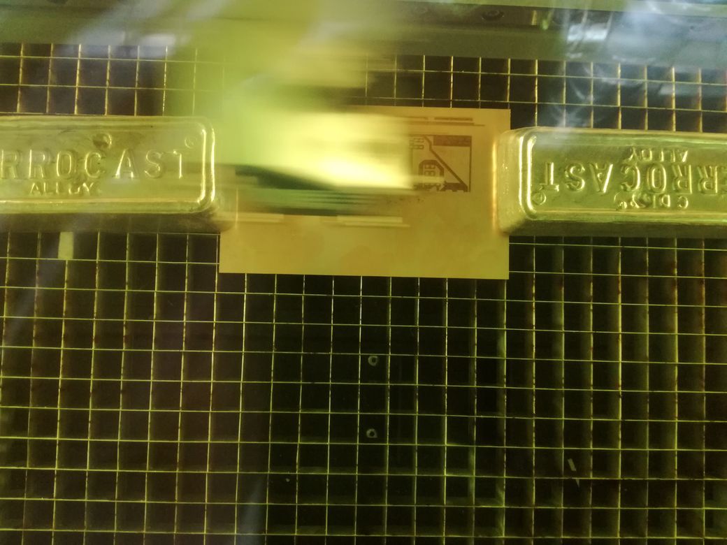
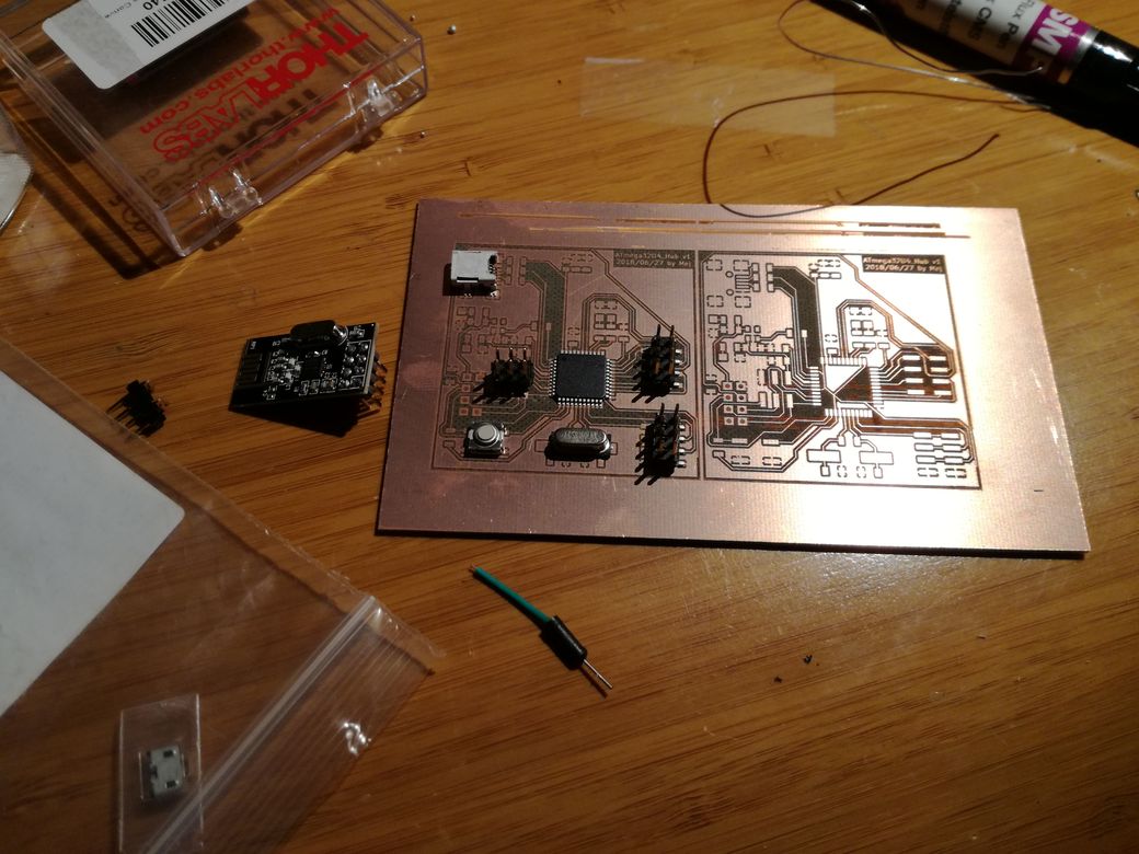
Production
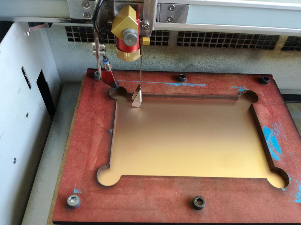
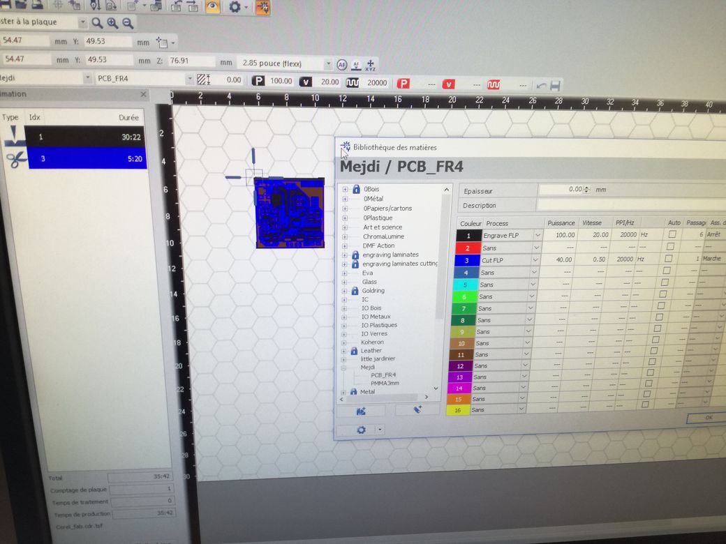
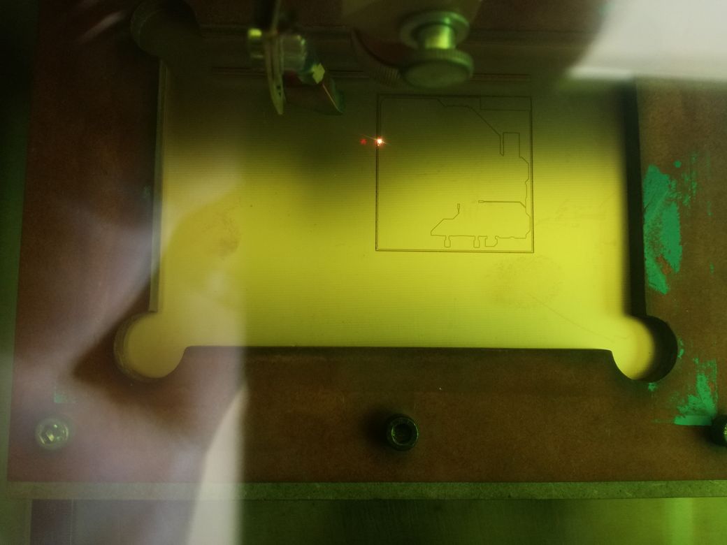
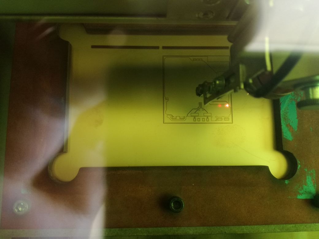
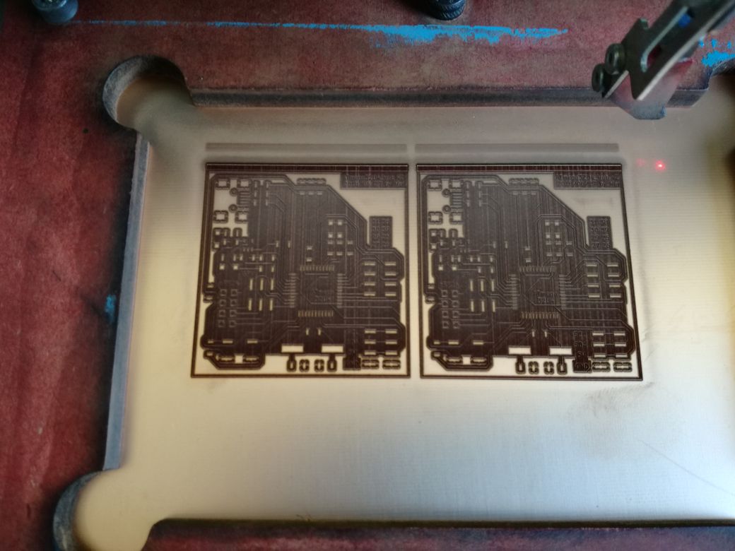
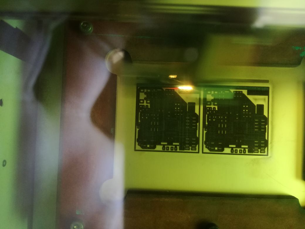
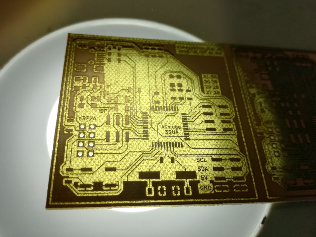
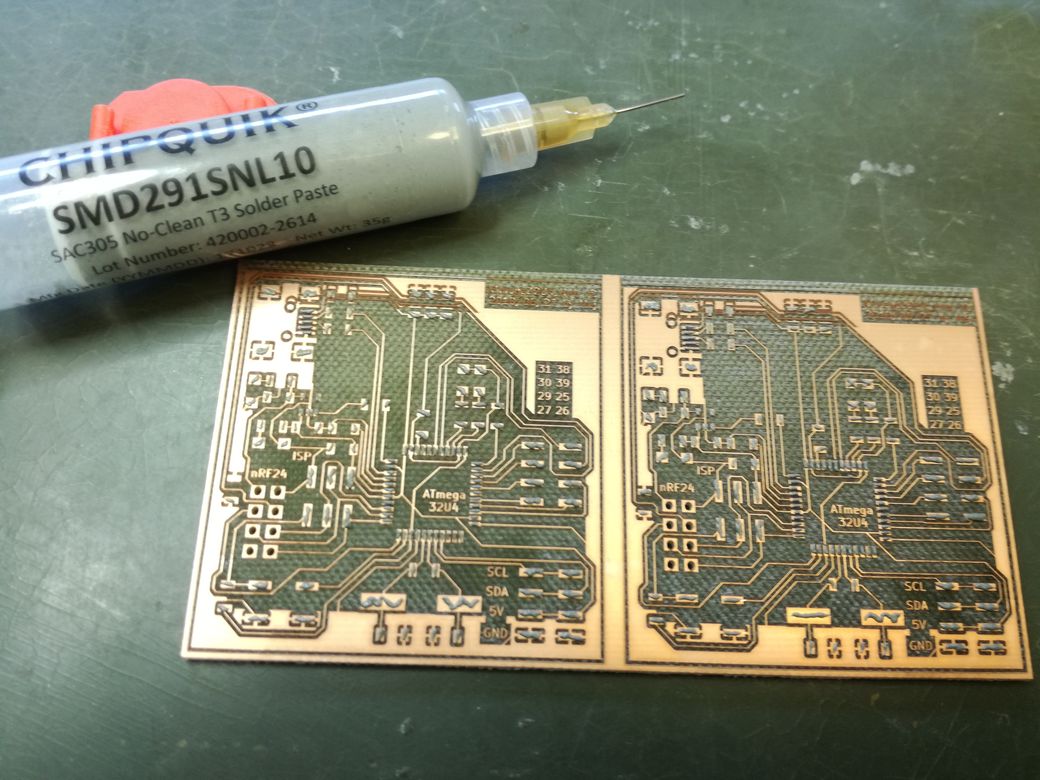
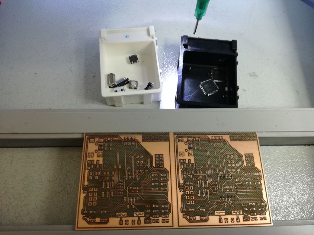
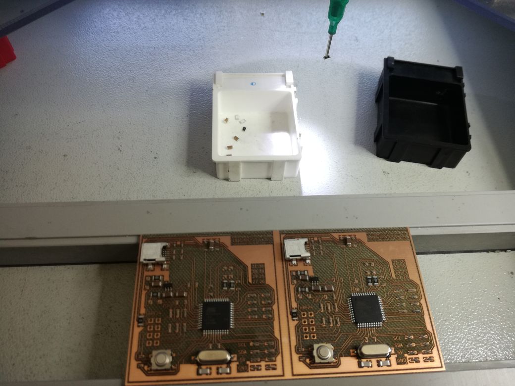
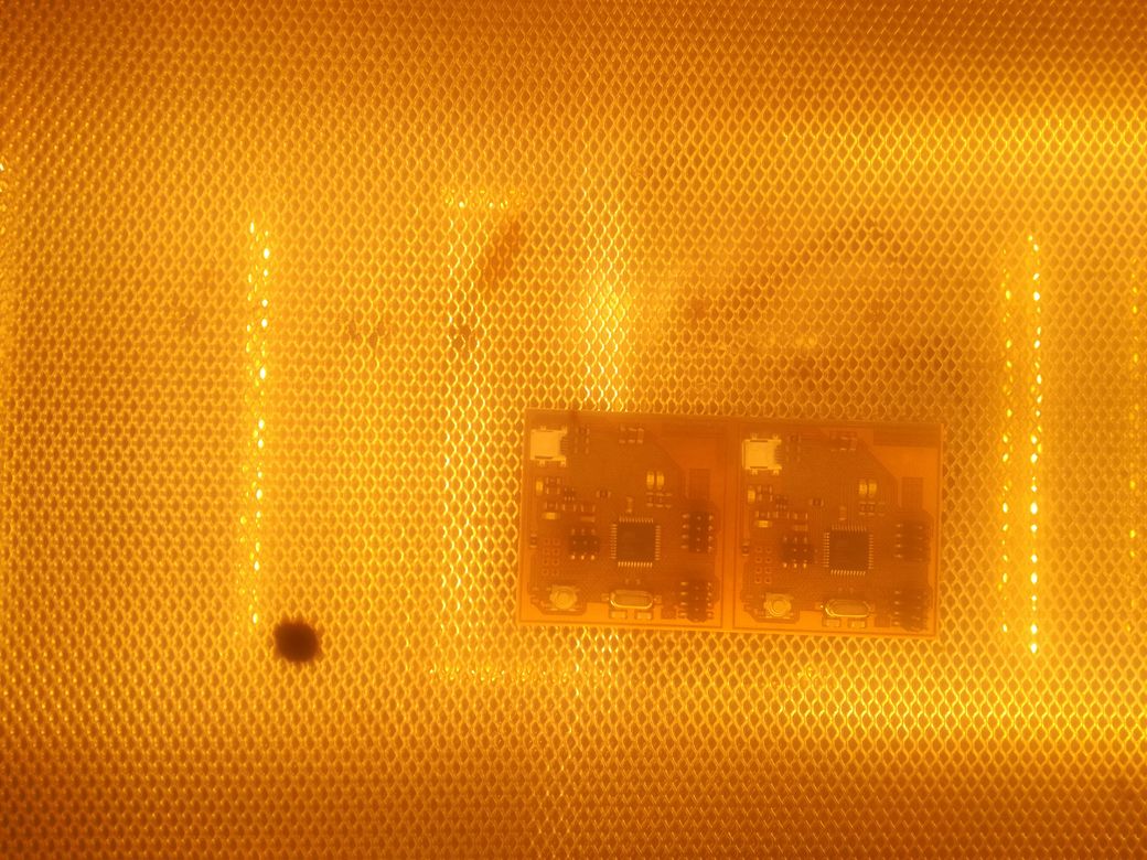
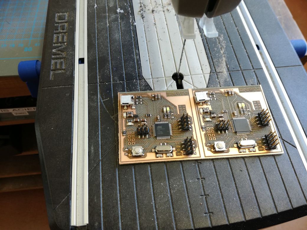
Using my a custom ATmega32U4 PCB
Wake up
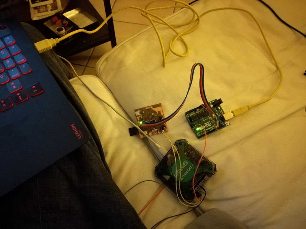
Bootloading with arduino IDE, via external ISP programmer
Following this tuto, I flashed an Arduino Uno to make it a ISP Programmer.
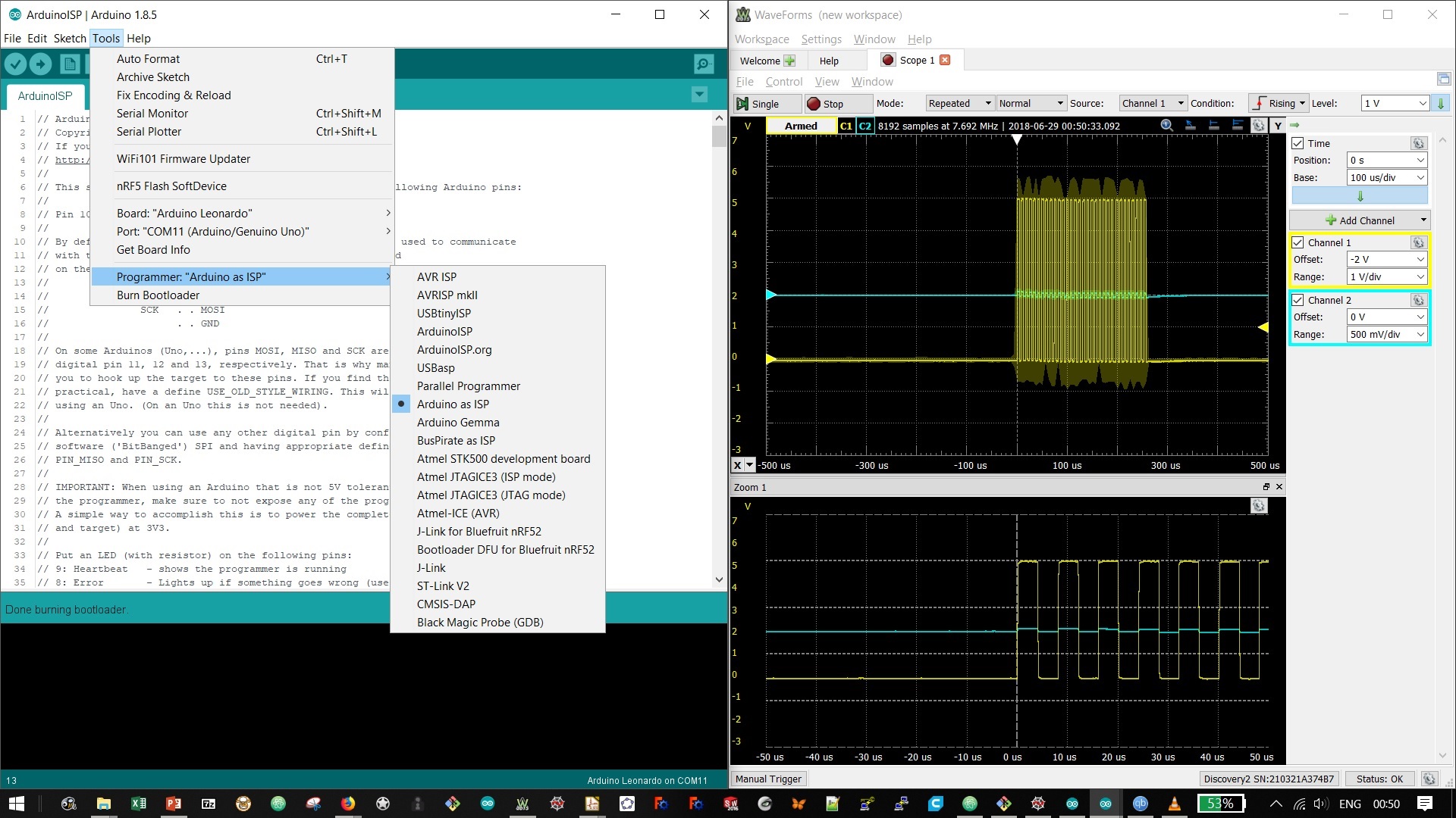
Then, I used the Uno to burn the Arduino bootload on my ATmega32U4 (via the ISP connector), as if it was a Arduino Leonardo board.
I used my Anolog Discovery to monitor the clock of the ISP bus: the burn takes few minutes and I wanted to be sure data was actually being transfered ^^.
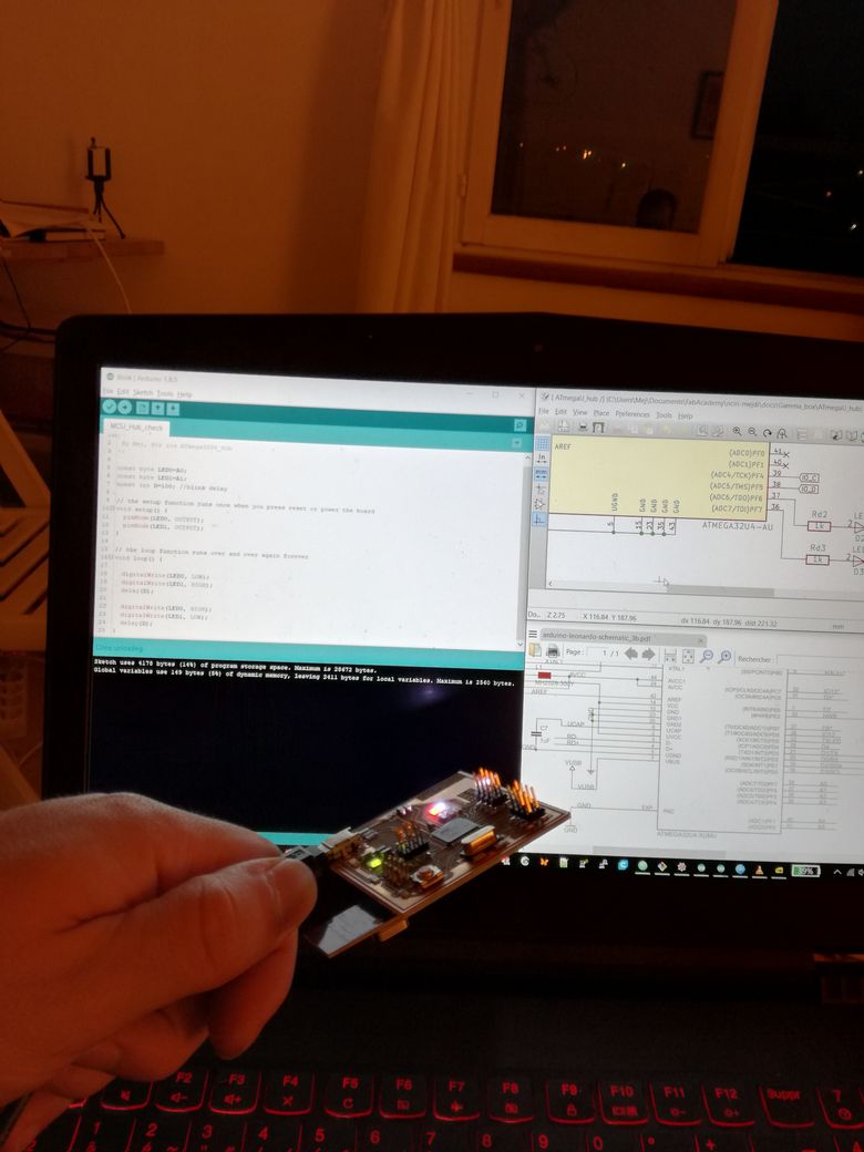
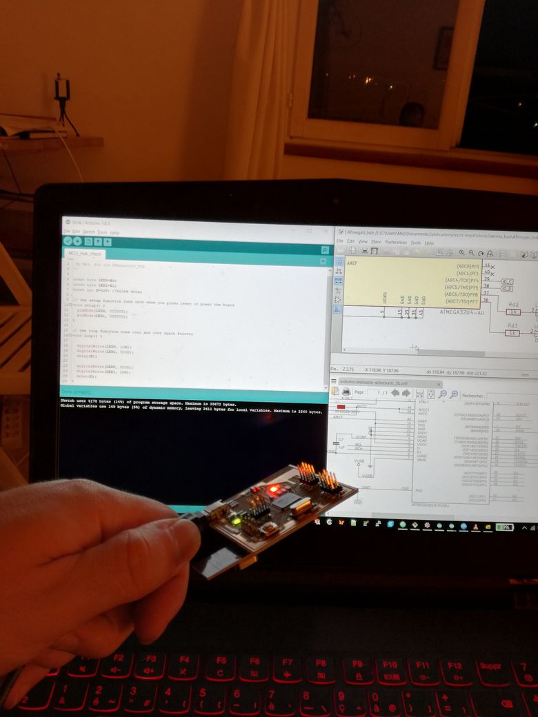
Flashing with Arduino IDE, via USB
Using the Arduini IDE, I can now programme my pcb as if it was the Leonardo board. Both my board blink!
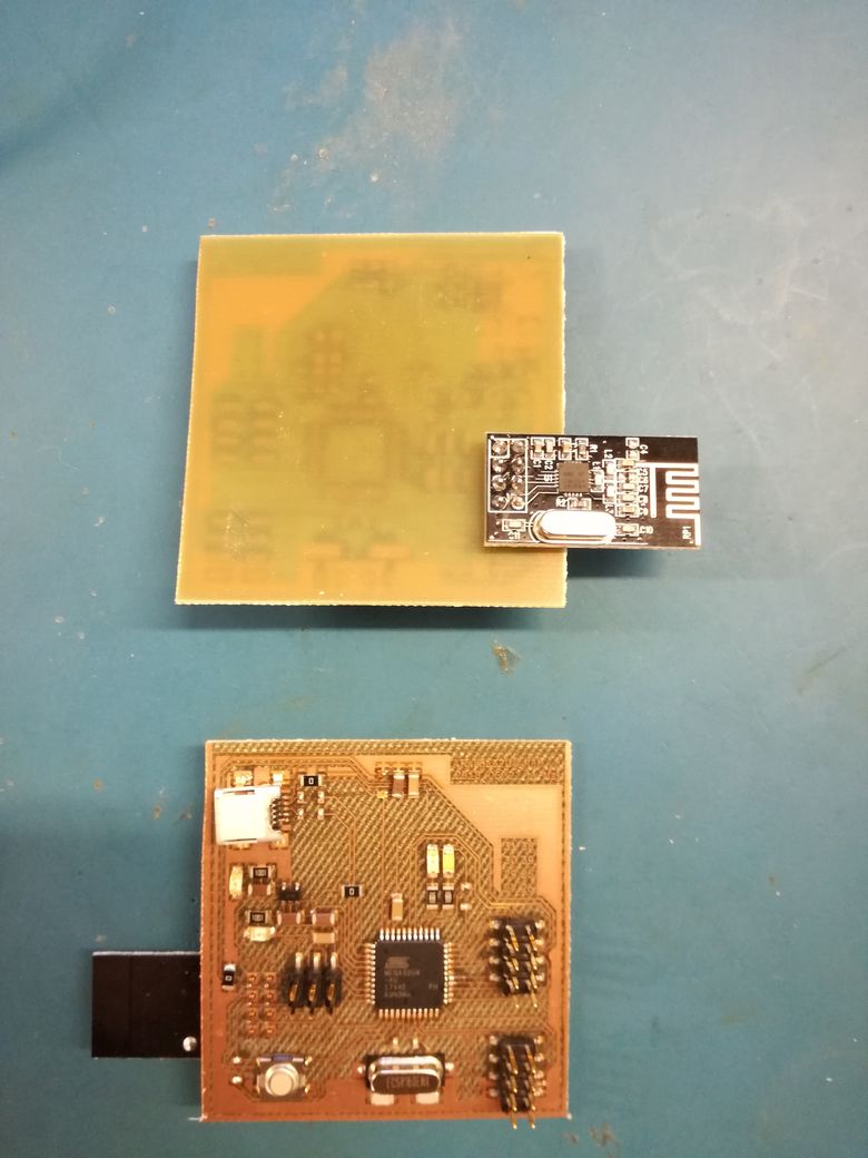
nRF04L01 module
A nice tutorial, with video,
on how to use the nRF24L01 module with the Arduino IDE.
It uses this library, that you "install" by extracting the repo in the Arduino/library/ folder.
In my case, it is C:\Users\Mej\Documents\Arduino\libraries\
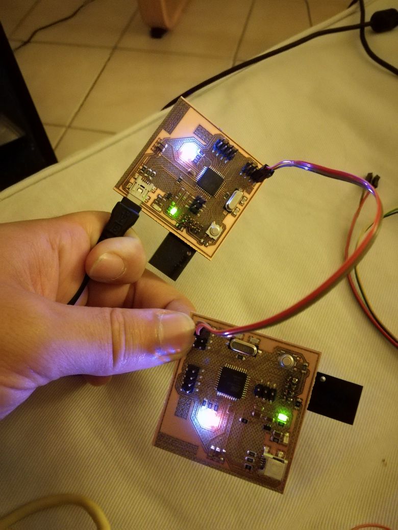
RF com between 2 pcb
I achieved RF communication!
The video, is actually from the 1st version of the code, whith bad synchronisation.
It works perfectly with this code on the "emmiter" board
and this code in the receiver board.
NB: The maximum payload size (ie the size of the biggest packet you can send) is equal to 32 chars (32 Byte).
Big data transfert should be done one packet at a time.
Back to Mejdi_FabAcademy_FollowUp