Back to Mejdi_FabAcademy_FollowUp
Week13: Output devices
Assignment:
- add an output device to a microcontroller board you've designed and program it to do something
- measure the power consumption of an output device
Part of my final project.
1/ Designing the Main PCB with KiCAD
1.1/
1.2/
I decided to get rid of the MCU, but I still have tons of I/O to control and monitor.
I'll be using a I²C GPIO expender. I chose the PCA9555.
Sometimes the footprints are in the native KiCAD libraries:
Sometimes they are not and you need to draw them yourself. All the footprints I drew are
in the lib.pretty file of the KiCAD project directory .
1.3/ Rooting main-pcb v0
The shematic won't change much now.
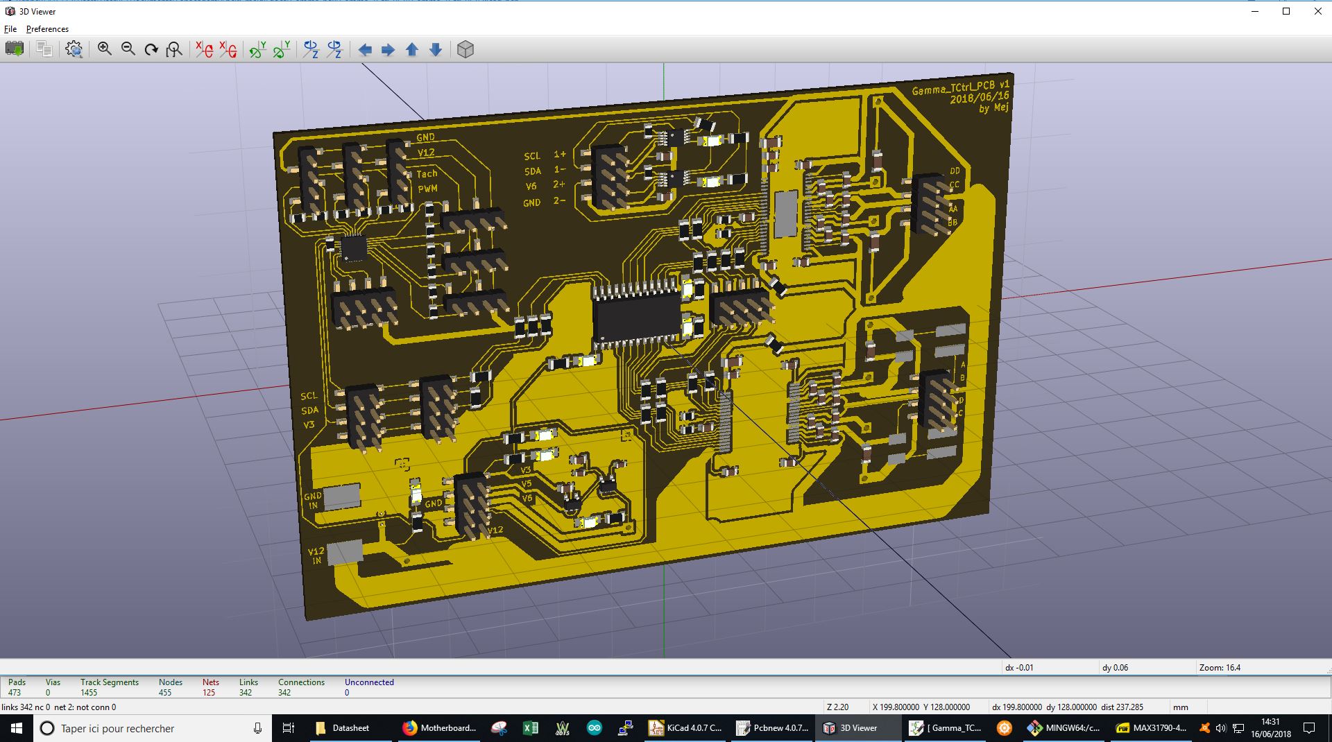
1.4/ Rooting Main PCB v1
I did have to add 18 jump resistors (0 Ohm) in order to keep the boad 1 layer. With 200µm tracks and 200µm clearance, it is possible to fit 4 tracks under a 1206 package!
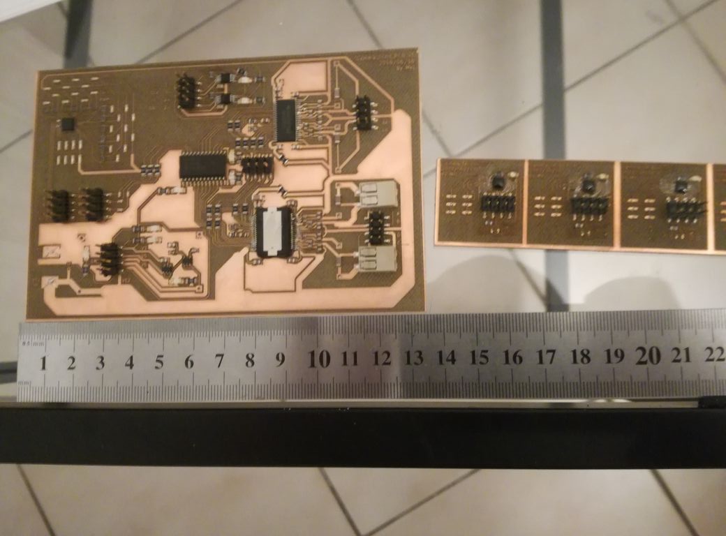
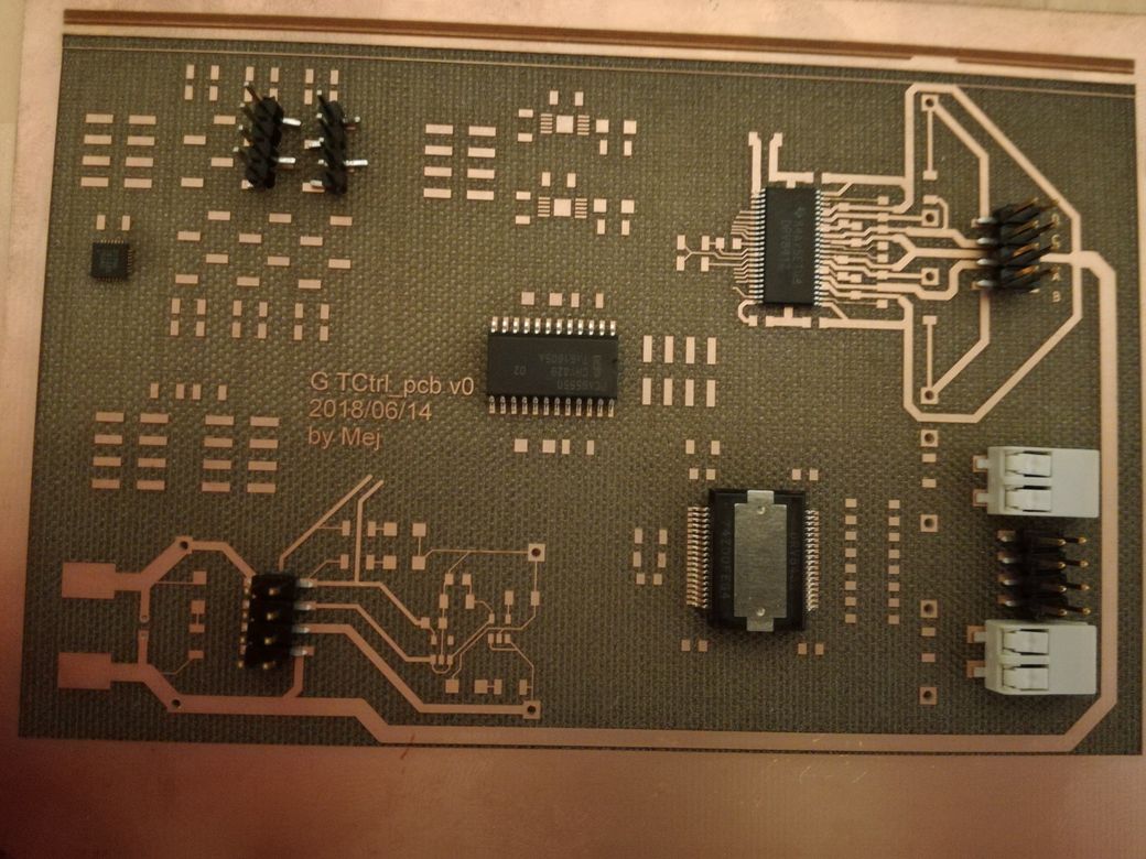
2/ Making Main PCB
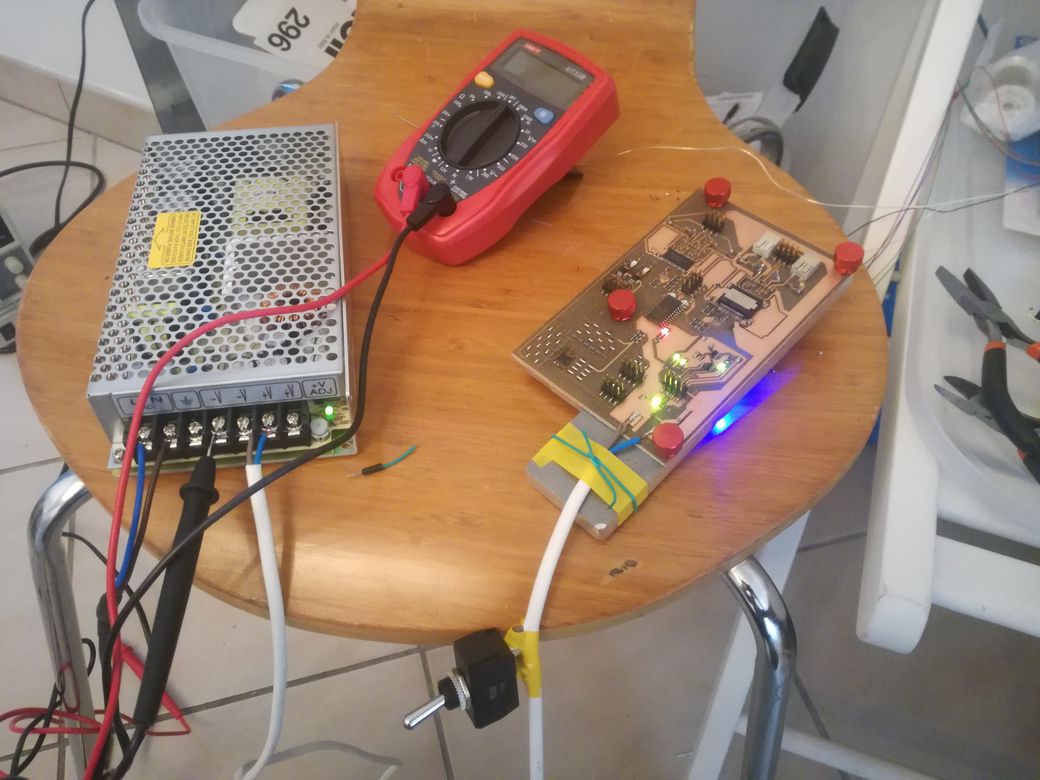
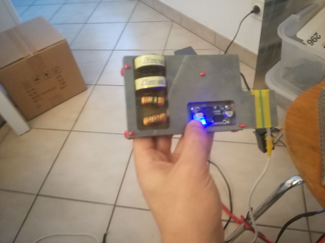
3/ Testing Main PCB
I wrote little sketchs with the Arduino IDE in order to test the I²C ICs of the bord: