Back to Mejdi_FabAcademy_FollowUp
Week12: Input devices
Assignment:
- measure something: add a sensor to a microcontroller board that you have designed and read it
- measure the analog levels and digital signals in an input device
Part of my final project.
1/ Designing the Probe PCB with KiCAD
I decided to use the MCP9804. My memorundum here.
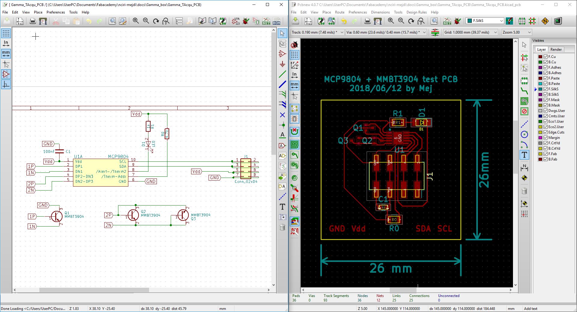
For channel 1 (Q1), I connected the collector of the transistor to ground. For channel 2 and 3 (the anti-parallel ones)I connected the collector to the base of the transistor.
If this test PCB work, I'll make one that can easilly be connected to probe diode/transistor via a thin wire.
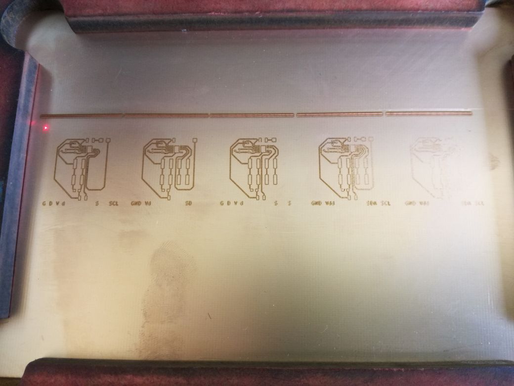
2/ Probe PCB Production
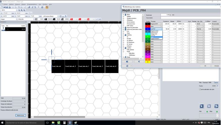
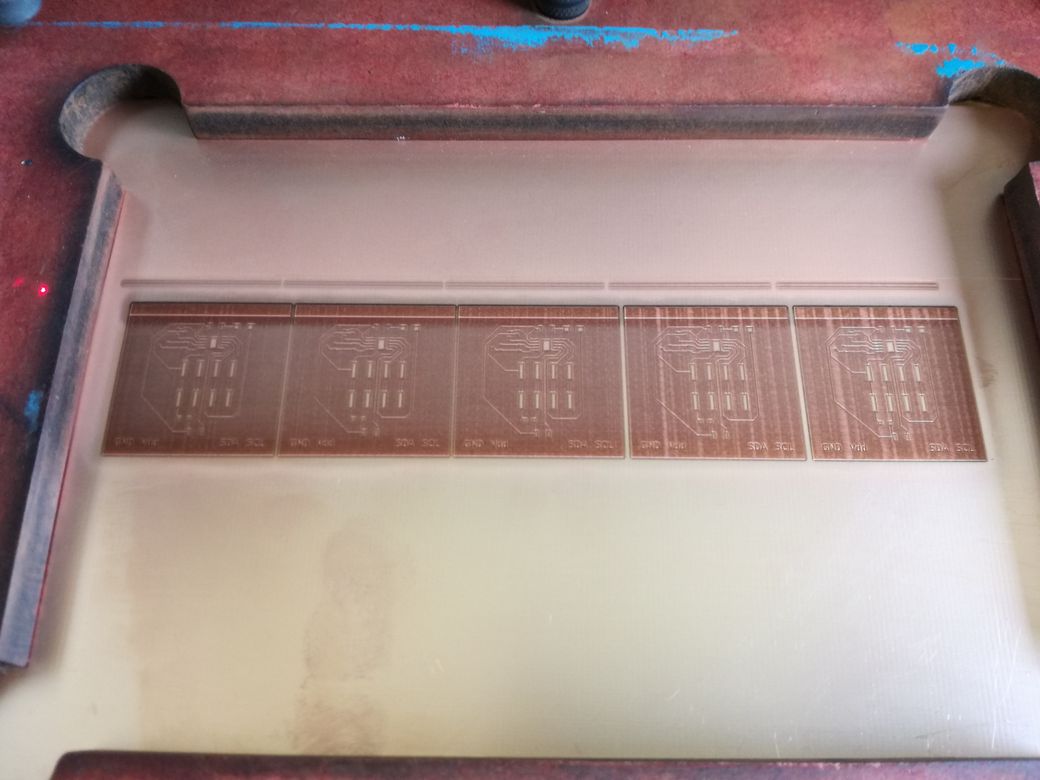
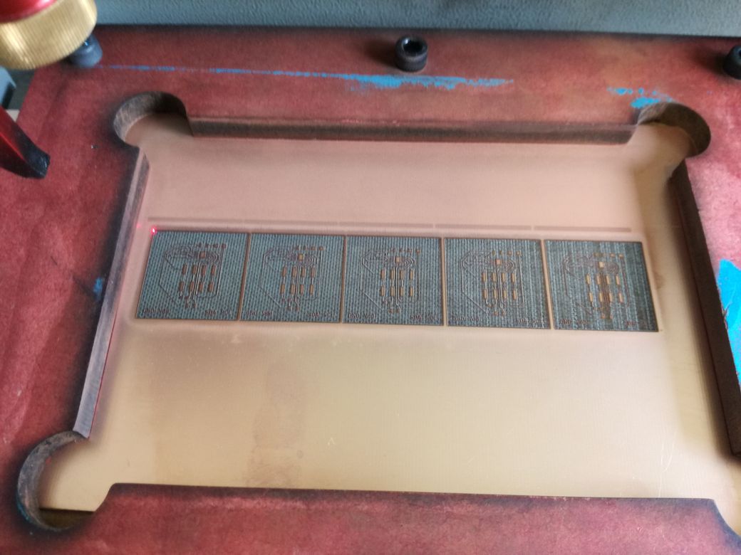
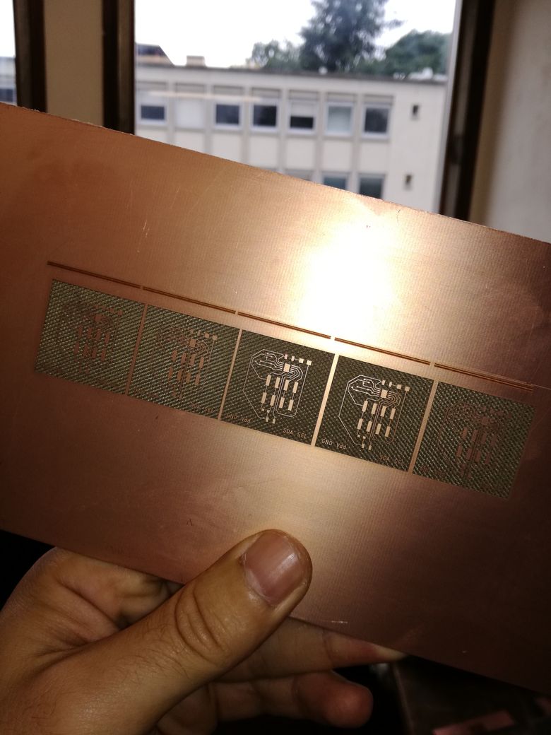
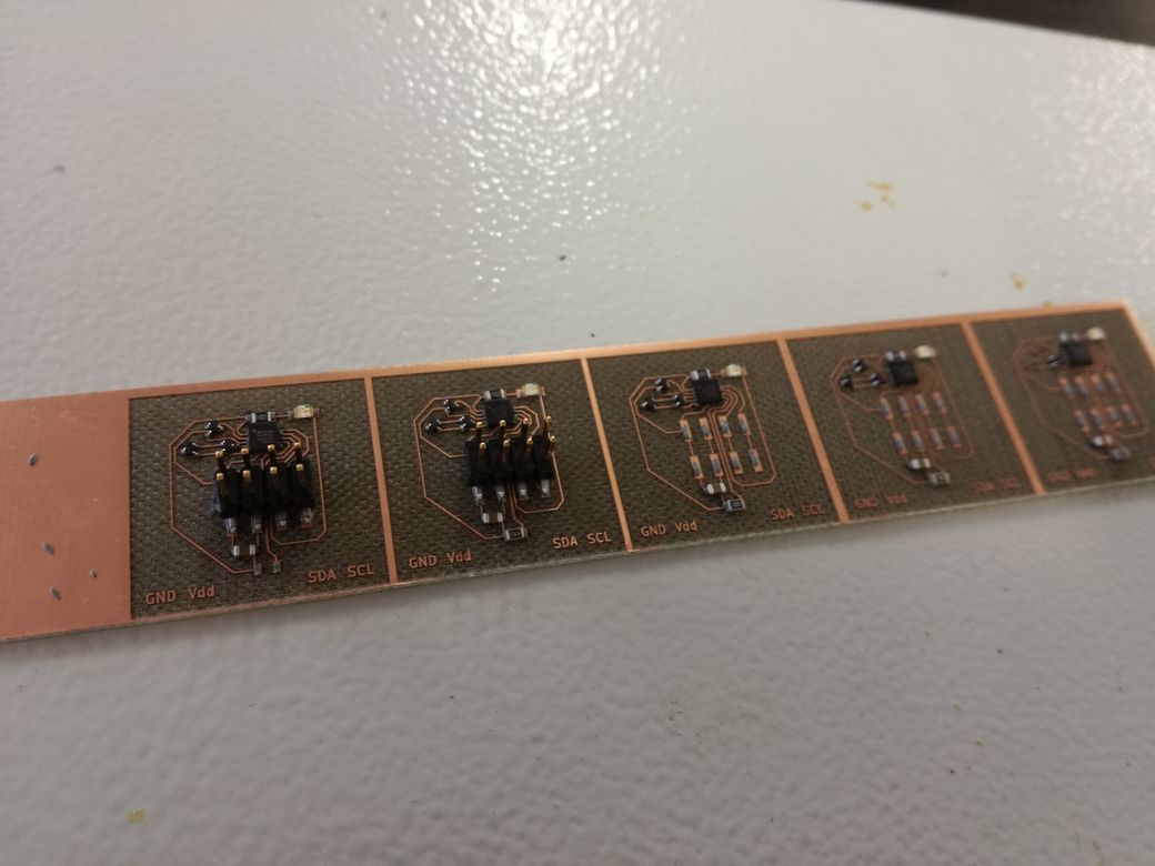
I chose a MCP9804 with a VDFN-10 package. Very small: pad width is 0.3mm and pad pitch is 0.5mm.
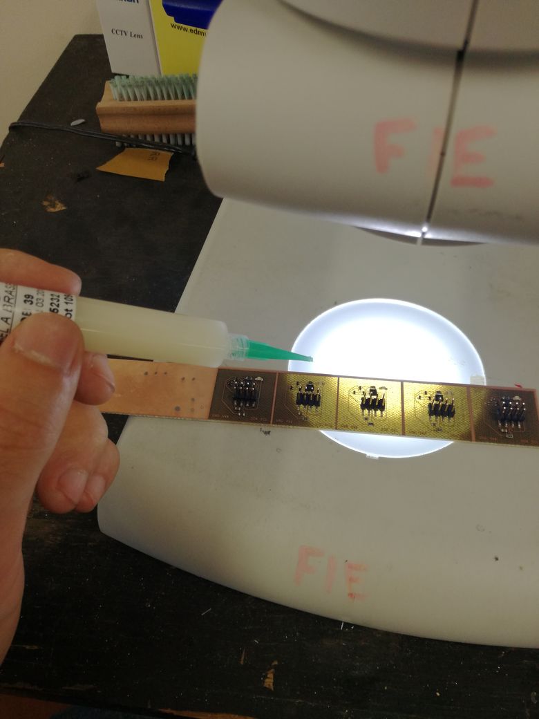
After reflow oven, i need to clean the soldering using flux and a soldering iron under binocular.
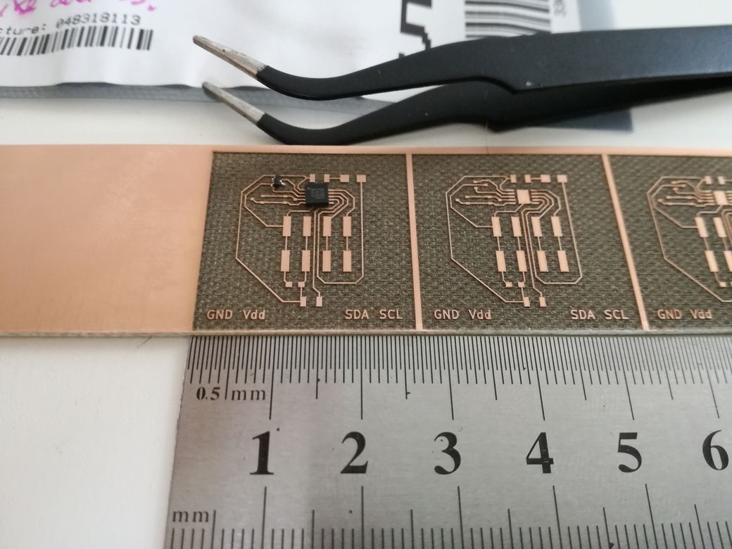
This PCB can measure its own temperature, and the temperatures of 3 remote transitors's diode, with +/-1°C accuracy and communicate it through I²C.
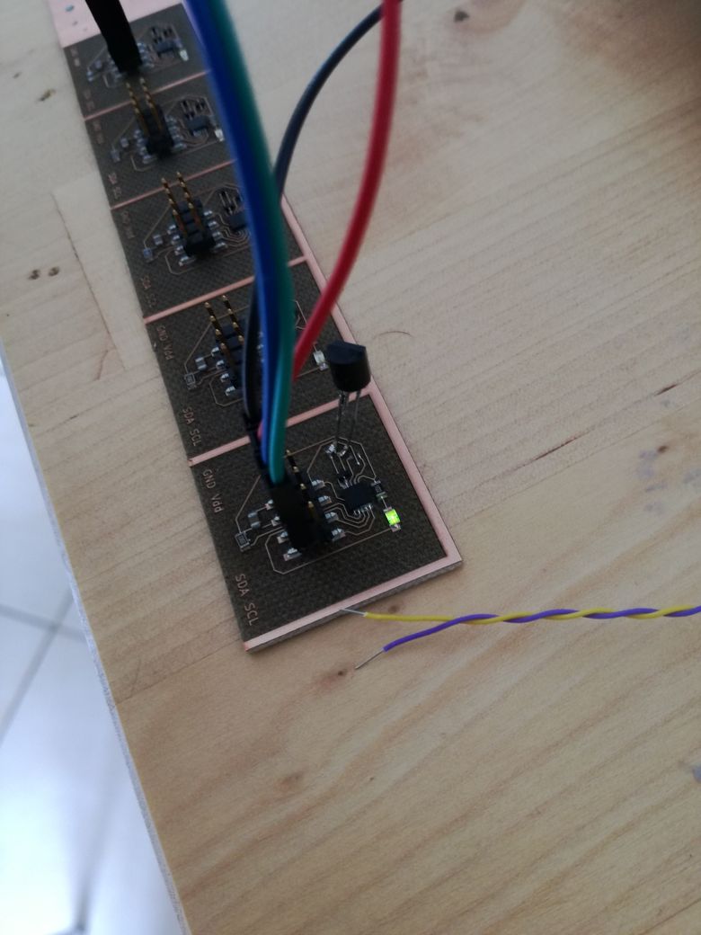
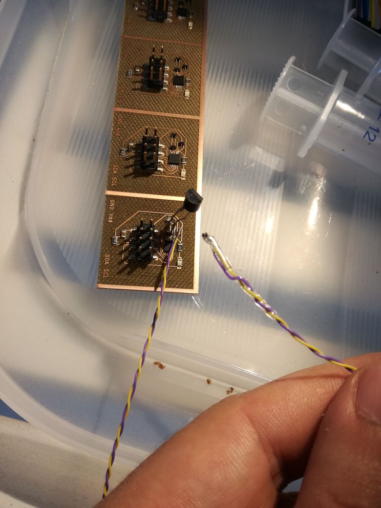
For now the transistors are soldered on the PCB (top left). Later thin wires will connected the transistors to the PCB.
3/ Probe PCB test
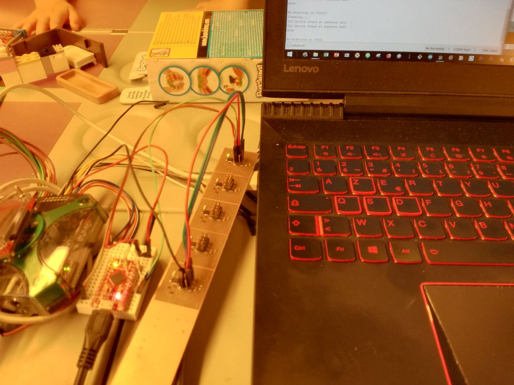
To test the pcb, i wanted to use a a leonardo, but i coudn't find it ^^. I used a pro-micro of sparkfun instead.
Its a 5V board that doesn't have 3.3V regulator, and the MCP9804 only work up to 3.6V... I used a Analog discovery of digilent as a 3.3V source.
On the 5 circuits, only 2 works: the first and the last. I blame it on the solder paste: it had been out of the fridges for few days. Smal package need premium solder paste.
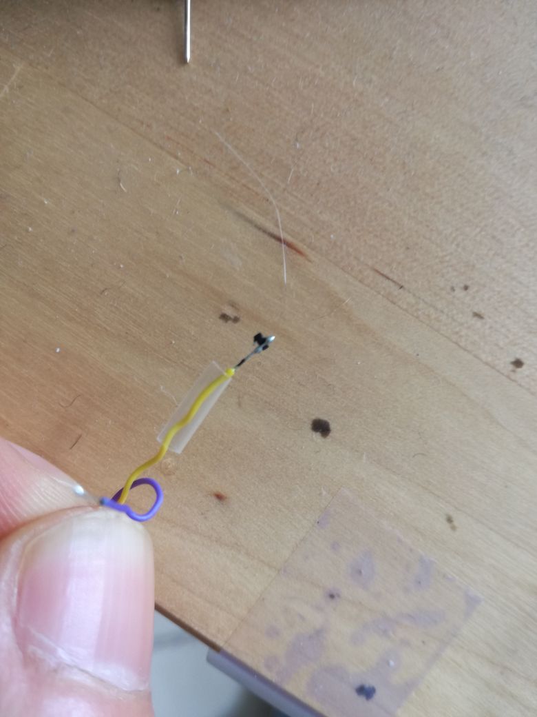
On the 5th circuit I soldered a TO92 transistor on channel 3, and a SOT523 transistor on channel 1, through thin wires.
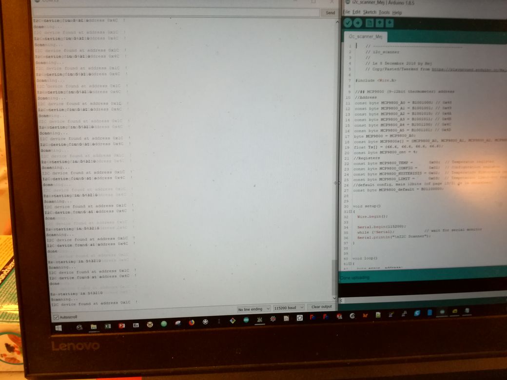
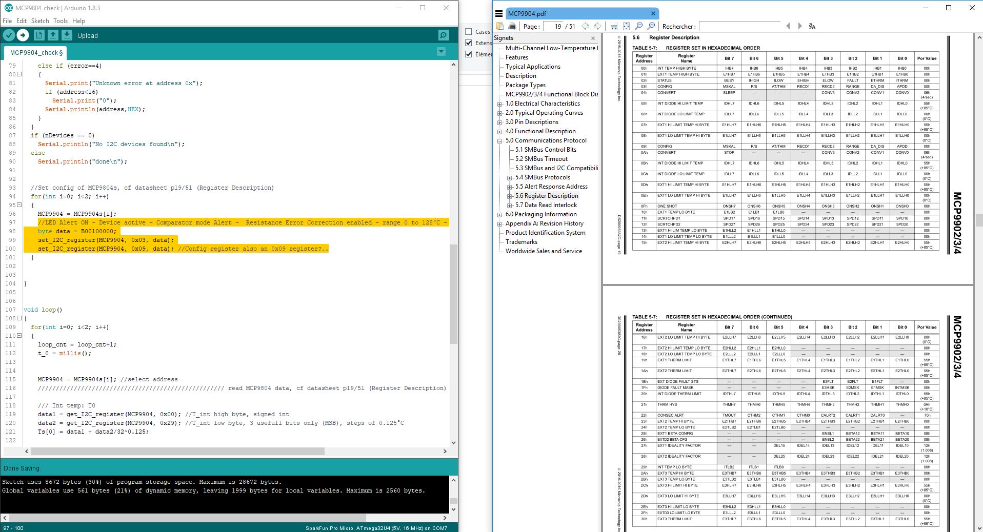
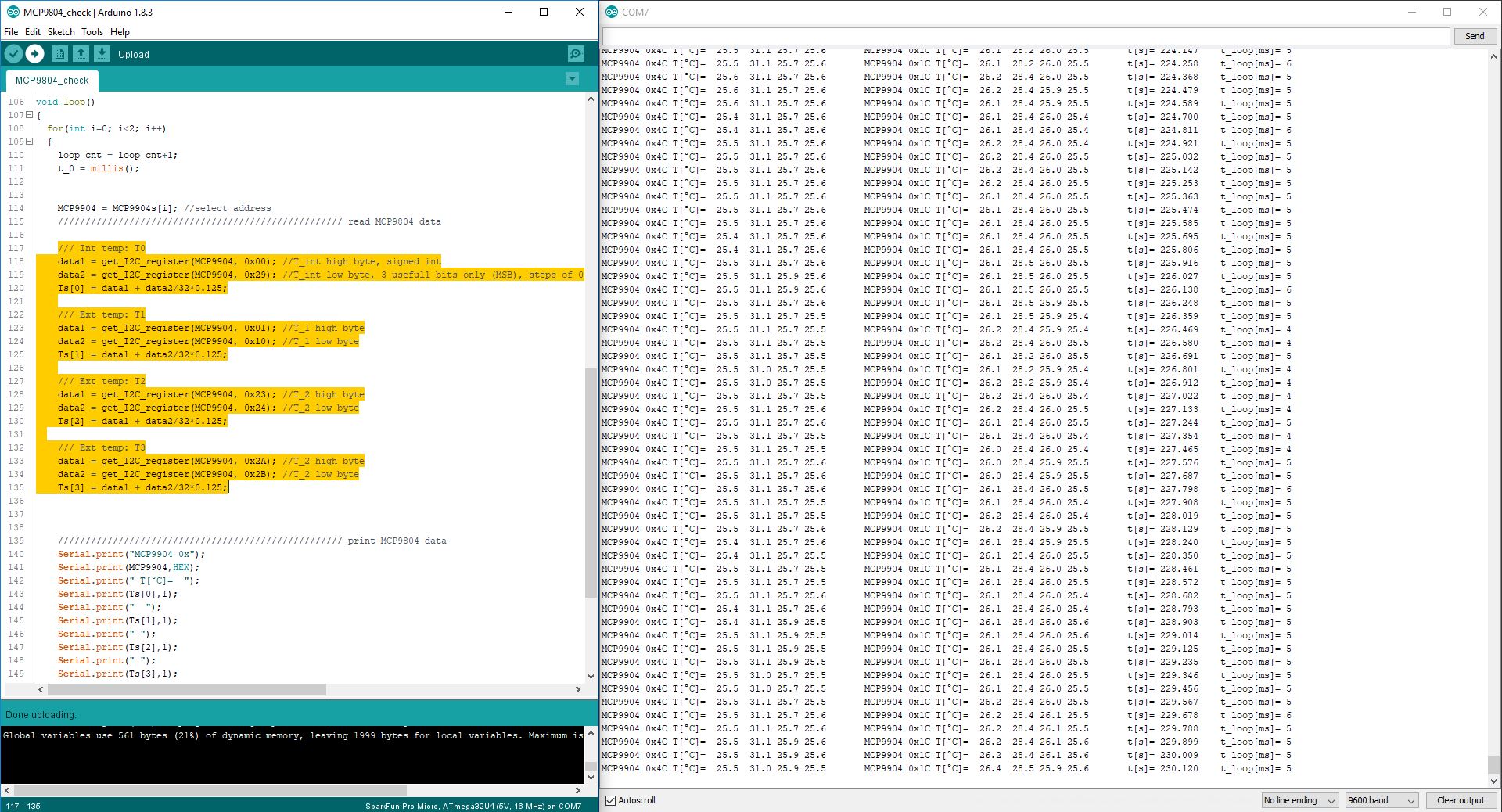
I wrote this programme to read the temperatures in the I²C registers and outputs them through serial:
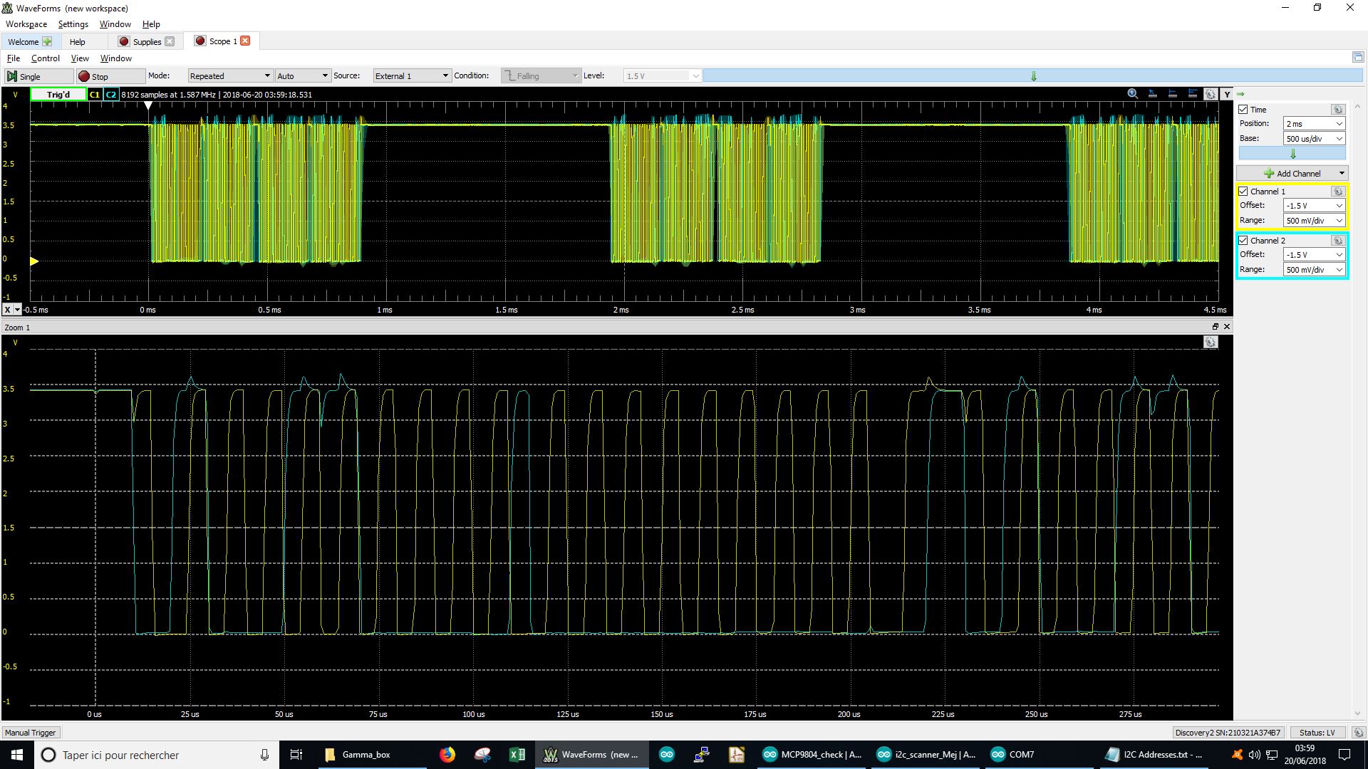
With the 2 channel osciloscope of the Analog Discovery, it is possible to observe the I²C signals: SCL (C1, in yellow) and SDA (C2, in blue)
4/ Probe PCB advance testing
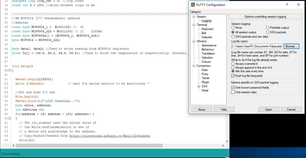
By using PuTTY it is easy to monitor and save the serial output in a file:
here is a exemple of such a log.
For the first 15s I didnt touch anything, then for 30s I touched the sensors with my finger one by one.
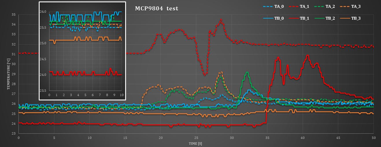
Then I touched them with a soldering iron. I didn't touch the sensor I just soldered on the thin wire (TB_1), to not unsolder it (I just put the tip of the iron very close)
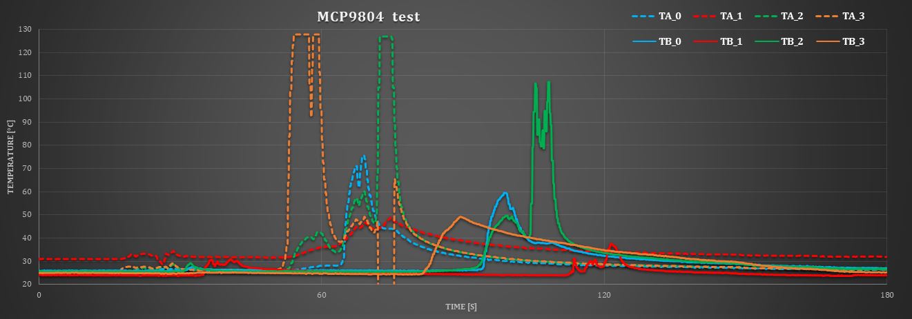
Excel graphs here.
Discussion:
- Transistor with collector connected to ground (Ta_1) is not a good idea: It increases the error due to the Beta variation of the transistor.
- SOT523 package heat and cool super quickly
- Internal temperature of the MCP9804 ICs (TA0 and TB_0) have more thermal iniertia
- The TO92 package has the more thermal inertia
- Noise level is very close the quantification step (1/8=0.125°C)
Back to Mejdi_FabAcademy_FollowUp