-
Assignment
Electronics ProductionElectronics Production
I like electronics! doing circuits and smart systems, maybe because these stuff related to my major. But I have not done PCB circuits using Roland milling machine. I've tried that once before using laser cutter with non-refliction tape. I was so excited to get this done. First I started to build the circuit from scratch in order to arrange the paths and get the simulation before circuit fabrication. I used Fritzing software it's realy useful and easy to use. I used to use proteus software to do the testing and simulation with schmatc digram as well. I will start explaining what I did exactly
1. Fritzing Software
I downloaded the software
then I started implimenting the circuit by putting the components and making circuit connection. The goal of our assignment is to build ISP (in-system programming) to be able to program the circuit through USB, let's define the circuit main component attiny45

The circuit impelemintation using Firtzing, breadboard view
The circuit impelemintation using Firtzing, schmatic view
The circuit impelemintation using Firtzing, PCB layout
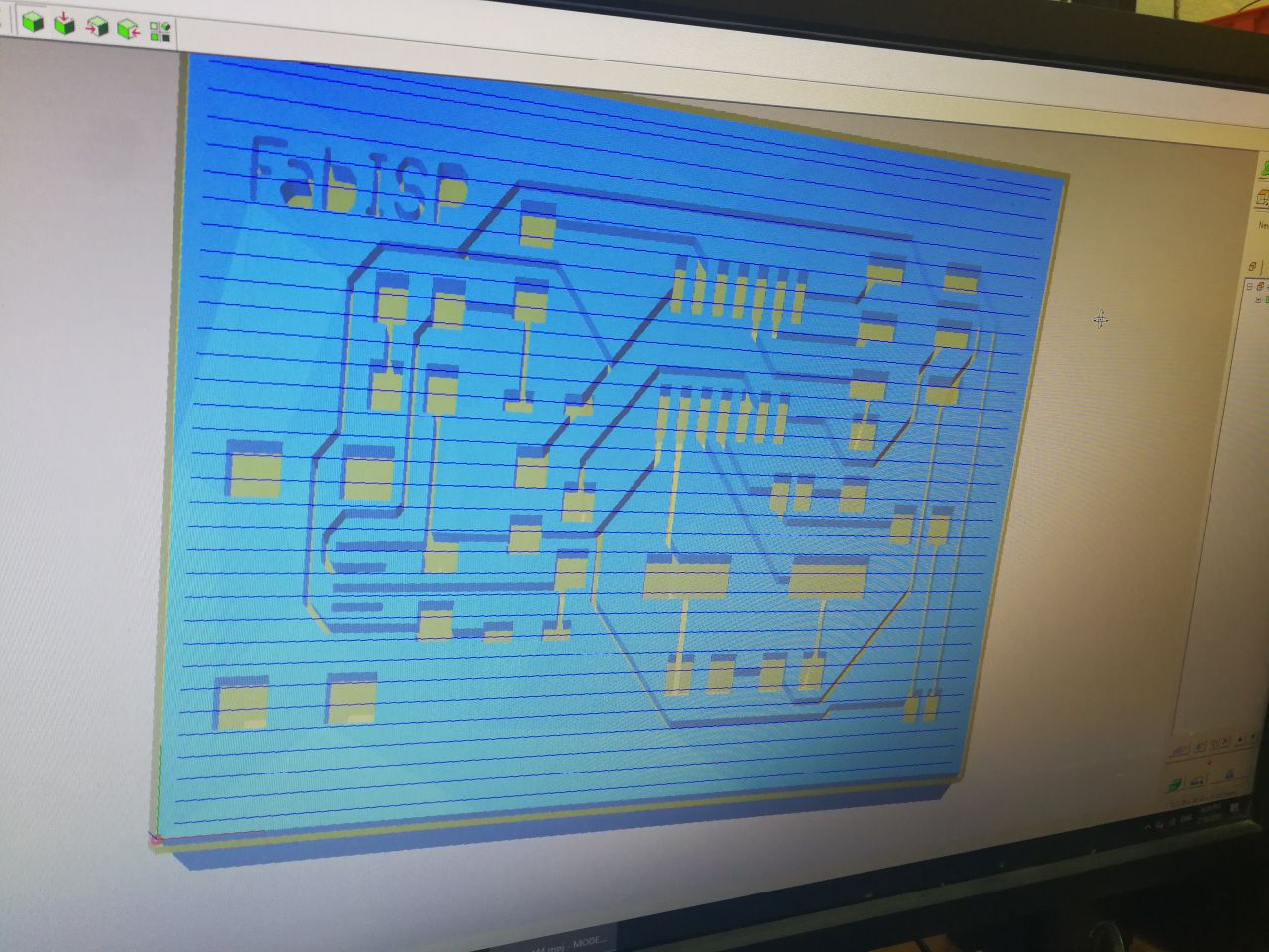
I tried to do the PCB using extrude tool in the Onshape, and then open the file using Milling machine software

Then I moved to use the Ubuntu OS to use Fab modules website
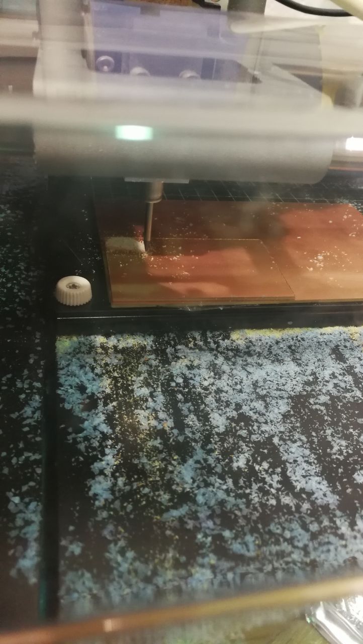
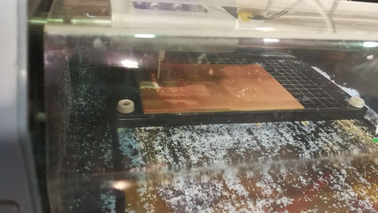
The website works perfectly! and I import the PNG layout file and export rml file, I used Roland MDX-20 milling machine to start create the paths and edges cut


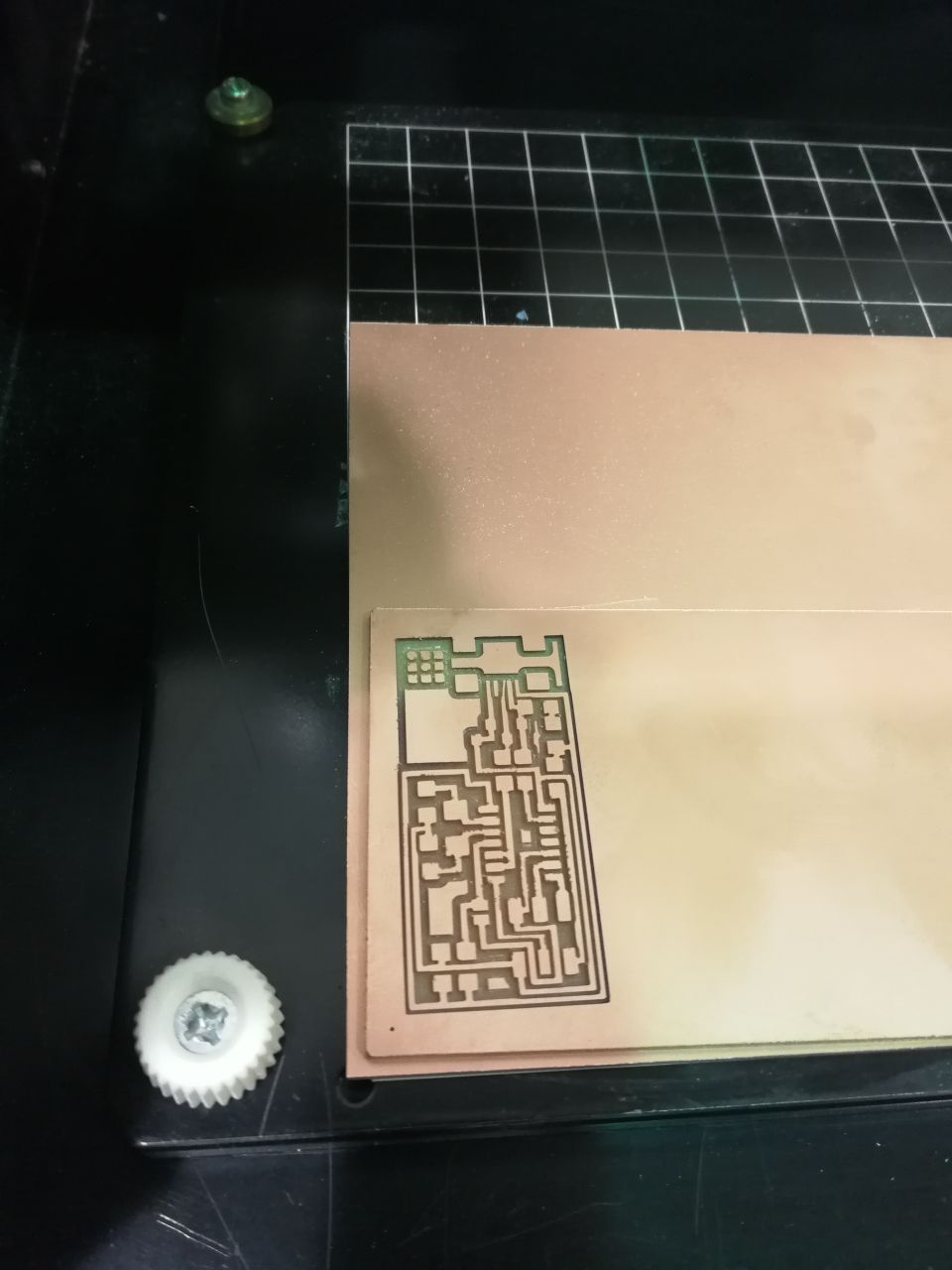
Finlly ,,, I got an amazing one!
