Week 14: Mechanical Design, Machine Design
MECHANICAL DESIGN (week 1 of 2)
Make a machine, including the end effector, build the passive parts and operate it manually.
MACHINE DESIGN (week 2 of 2)
Automate your machine. Document the group project and your individual contribution.
Learning outcomes:
- Work and communicate effectively in a team and independently
- Design, plan and build a system
- Analyse and solve technical problems
- Recognize opportunities for improvements in the design
Have you:
- Explained your individual contribution to this project on your own website
Source: Fab Academy Assessment - Mechanical Design, Machine Design
My Process
Background
I was excited about this week - and still am. I have been very interested in machine design for a while. I worked on open-source 3d printers and a lasercutter during my time at Open Source Ecology and really enjoyed the challenge of integrating mechanical design, software interface, and motion actuation. I think if I were 18 years old again I might try to study mechatronics or systems engineering for my undergraduate degree.
Anyway, I spent a lot of time mulling over what kind of machine I hoped we might build. Some ideas I had included:
- Small CNC machine (e.g. for circuit milling)
- Grinder for cutting our own millbits (ambitious, to be sure)
- A domino setting up machine (like this one)
- Phone/Tablet tapping machine (with a stylus so you can have a computer play games or do repetitive tasks on a touch screen)*
*This is an idea I had later in the process, so it's not in our group brainstorm - still something I'd like to build at some point.
Getting Started
We started off by all coming into the lab on a Saturday to do some brainstorming and planning. There were lots of good ideas in the group, so we spent some time getting them down. I started a Google Doc for us to start tracking them. Here's the list we came up with:
- automatic card-dealing machine
- frosting/chocolate extruder
- batik wax drawing machine
- small CNC mill
- portable x/y axis machine (e.g. that could draw on a whiteboard)
- filament melter/extruder/recycler
- automated vegetable chopper
- hot wire cutting machine
- wire/pipe bender
- automatic phone answering machine
- paperclip maker
- farming/gardening robot
- etch-a-sketch machine
- zen robot (sand art robot)
- Jenga setup robot
- dominoes setup robot
- micro photo booth - just add smart phone
- stop motion camera setup
- dolly for camera / timelapse photography
It was an overflowing list, and we needed a way to narrow down the list and home our discussion in on a couple that we wanted to seriously consider. I suggested a process that I know from co-operative decision making; I've heard it referred to as "dot voting". Everyone gets up to 4 votes (or dots) which they can place on any items in the list. If they really love an idea and want it way more than anything else, they can put all 4 dots on that one item. If they want to pick 4 that they like equally, they can spread them out. If they only like 2 ideas, but don't feel that strongly about them, they can do one dot each, and leave two dots "uncast". Anyway, it has a way of helping a few items rise to the top for discussion (though I wouldn't recommend it as a "final decision" tool, necessarily).
The 3 top vote getters were: card dealer, etch-a-sketch machine, and zen/sand art robot. This was a much more approachable list to discuss. We decided that sand art and etch-a-sketch were similar enough that we could just fold sand art into the etch-a-sketch idea. A number of us liked the card-dealer idea - I'd still love to make this sometime. I think it would be a fun, interesting activity, and as Jean-Michel suggested, could be a fun "hacking" activity where we take apart an inkjet printer and see how it handles paper and manages to serve up one sheet at a time. (We could even hack it further and use the stepper motors from the printer!) Anyway, a project for another day. We chose to make an Etch-A-Sketch drawing machine.
A little background here: a couple nights before our brainstorming session, I was doing a Fab Lab demo for some young people at the Lena Park Fab Lab. I was showing them how the laser cutter worked, pointing out how the X and Y gantries moved the cutting head to cut or engrave an image. An 11-year-old named Michael said, "Oh! It's sort of like how an Etch-A-Sketch works!" , which was exactly true, and something I had definitely never thought of before. When I woke up the next morning, I was thinking about machine-building week, and I thought "Oh! We could make a machine to drive an Etch-A-Sketch! That would be fun!"
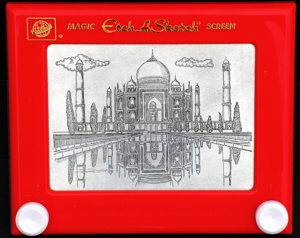
If you're not familiar, an Etch-A-Sketch (EAS) is a children's drawing toy. It has a screen and two knobs. Turning the knobs moves a stylus across the screen, drawing a line. To "reset" the screen to blank, you turn the Etch-A-Sketch over and shake it. There's lots of interesting stuff to learn about how it works, and it's truly a clever toy. Basically, it's a very simple X/Y plotter on the inside:
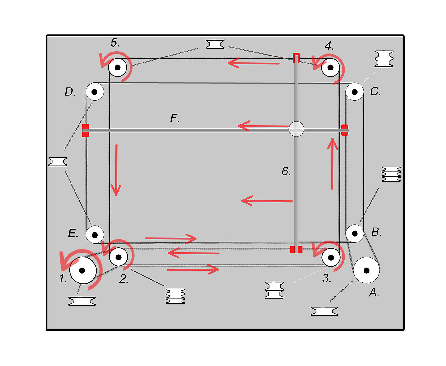
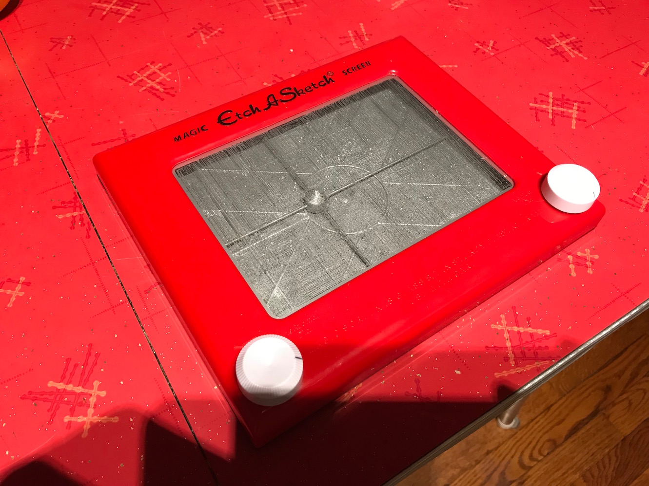
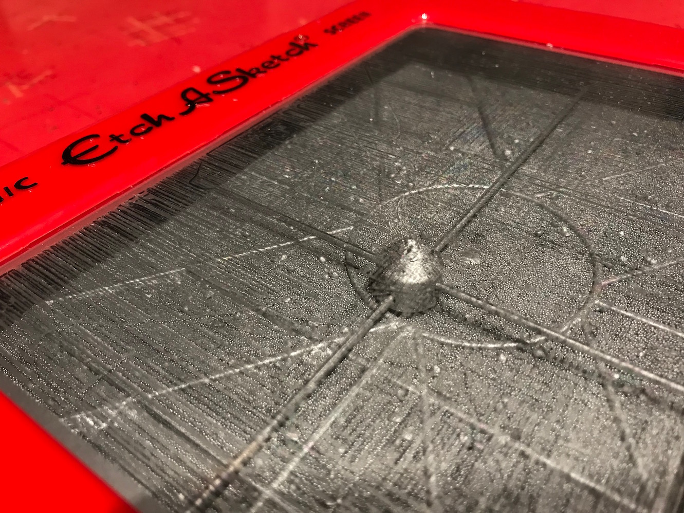
The plotter drags a stylus across the screen which knocks off a silver-colored powder, creating a dark line on the silver background. If you are meticulous enough, you can carefully drag the plotter back and forth across the screen many, many times and actually clear the screen entirely, illuminating the inner workings:
Mechanical Design
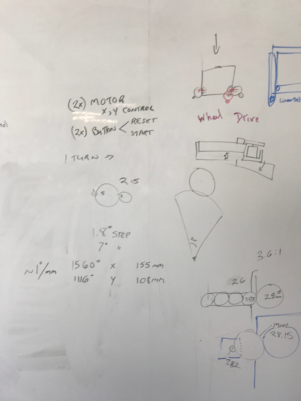
The key thing for our purposes is that there's an X-knob, and a Y-knob. We just needed to figure out how to turn them with computer control. We did some brainstorming and drawing on the Dassault Fab Lab conference room wall.
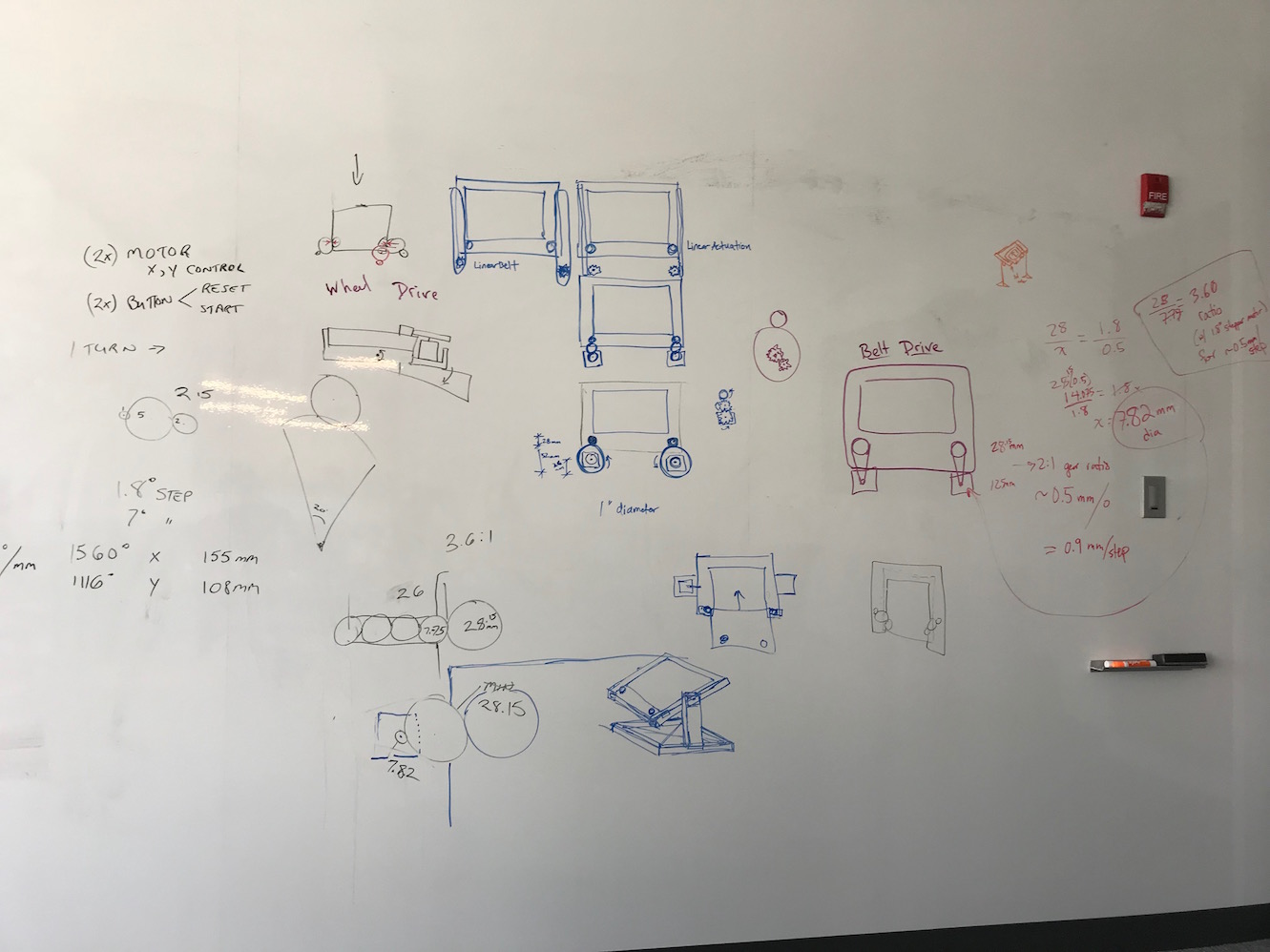
We talked about a number of different drive systems: a direct drive, with some sort of gripper on the stepper motor shaft that grabs onto the knobs and turns them directly; a belt drive system, where the stepper motor drives a belt that runs around the knob; a rack and pinion system, where a long driver is slid along the edge of the knobs; and a "wheel drive" system, where a solid wheel (with a gripping surface like rubber) is mounted on the drive shaft and makes a friction contact with the knobs to turn them.
There was quite a lot to consider, including measurements of the screen, step resolution for our control system and motors, the translation between degrees of knob turn and X and Y distance traveled.
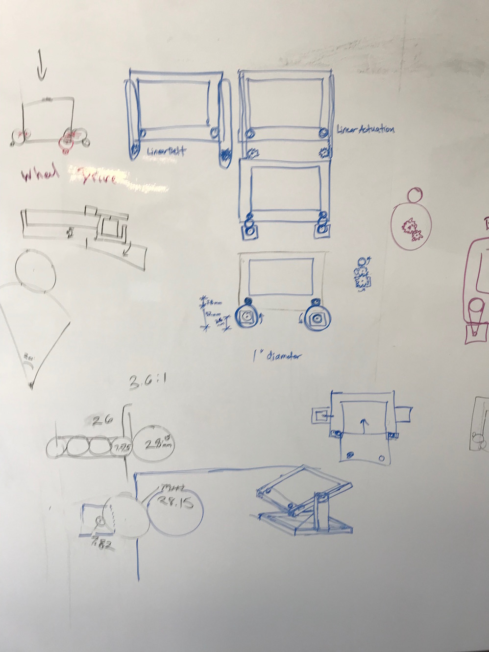
We also wanted a third stepper motor that could erase the Etch-A-Sketch by turning it over back and forth and/or shaking it upside down.
We discovered the following stats for the Etch-A-Sketch by measuring them:
Technical Info:

X travel: 155 mm
Y travel: 108 mm
knob_turns_X: ~4.33 turns = ~ 1560°
knob_turns_Y: ~3.10 turns  = ~ 1110°
Approximately 10° turn per mm travel
180° = ~ 16 mm travel
360° = ~ 35.5 mm travel

Smallest discern-able line separation = ~ 0.5mm
Note: knobs turn past their limits (internal rubber belt slips?) and then begin to travel back immediately when knob reverses direction (good feature!)

Knob diameter: 28.15mm
Knob height: 12.32mm
Base (incl. ridge) to top of knob: 40.42mm


Body
Underside: 186 x 227mm
Height incl. Ridge: 26.58mm
Height: 23.68mm
Gap from knob to side body edge: ~4.76mm
Gap from knob to bottom body edge: ~4.03mm

Screen Frame: Sides 32.8mm
		 Length (Top) 32.8mm
 Length (Bottom) 38.6mm
Fillet corner radius 7.8mm
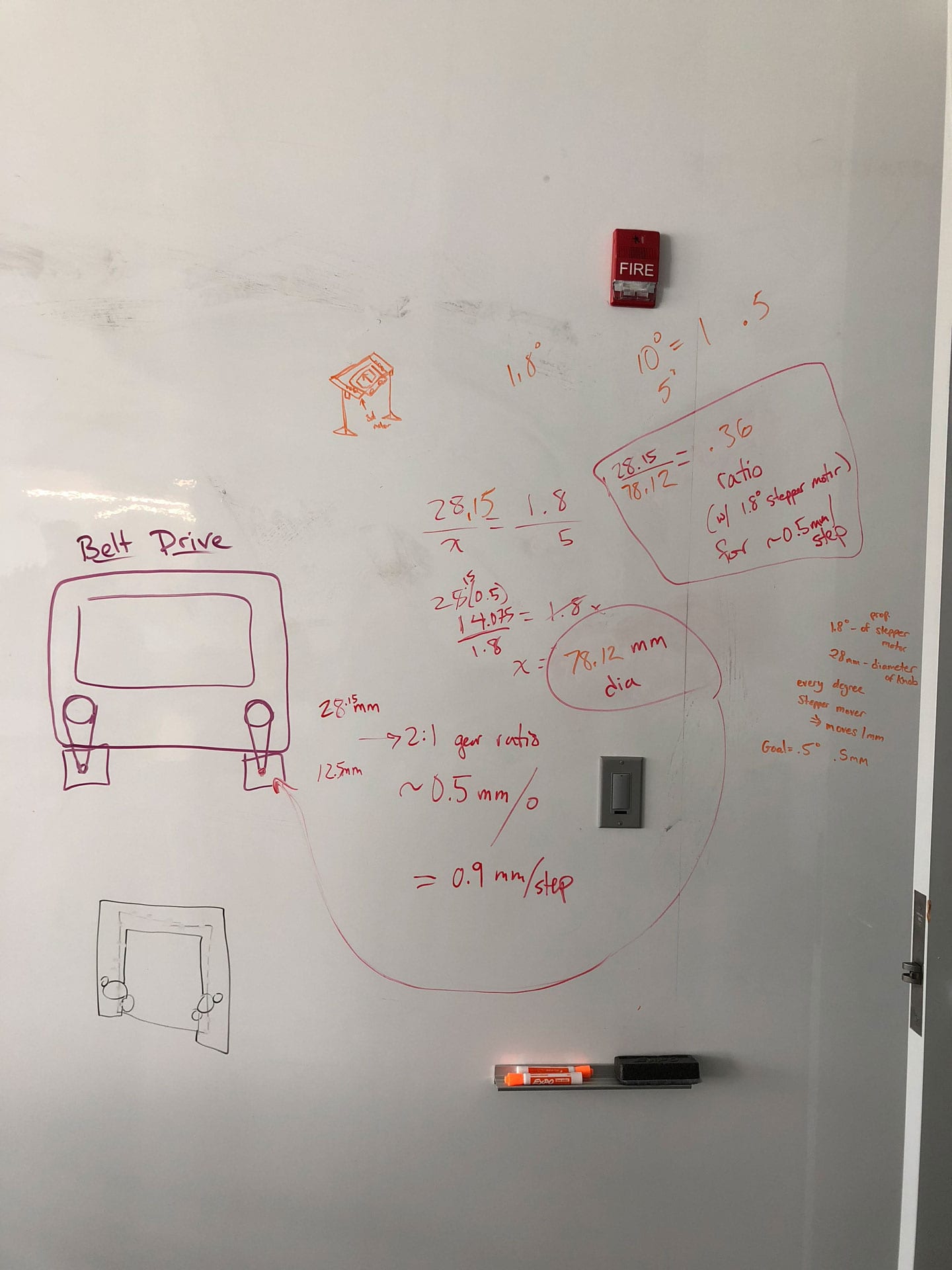
We used these specs to calculate the size of the drive wheel we would need, given that we had stepper motors with 1.8° per step, and we wanted to be able to operate the machine with a resolution of about 0.5mm of travel in the X or Y directions.
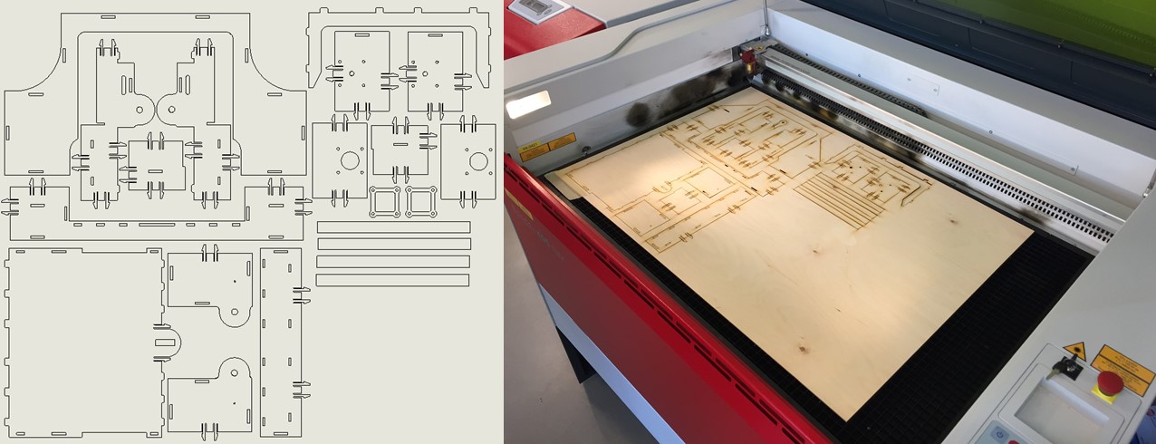
We designed & lasercut a simple wheel with a cutout in the center to fit around the gear on the stepper motor shaft (shout out to Sal Lama for his CAD skillz getting the gear cutout right on the first try). The diameter of this wheel we calculated to be 78.12mm. Fortunately, this was large enough to contact the knobs and still allow clearance for the body of the stepper motor.
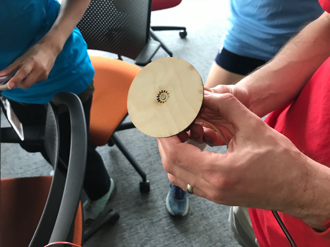
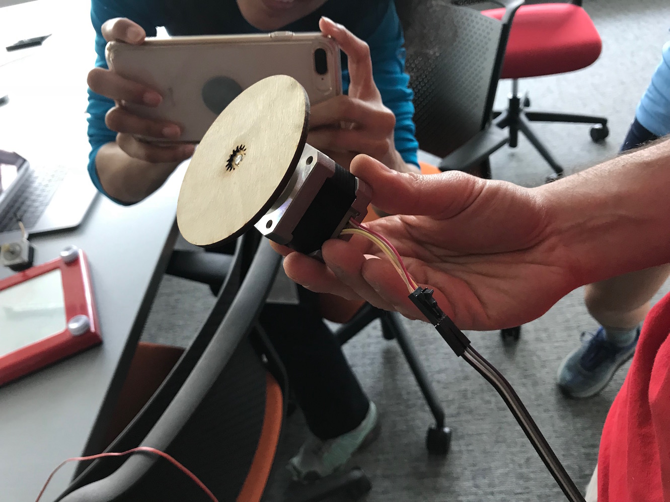
We put a thick rubber band around the wheel for added friction, and held the wheel/motor combo against the Etch-A-Sketch knobs. With only a little bit of orthogonal pressure, the turning wheel gripped the turning knob and turned it. We had our basic proof of concept! Next we spent some time thinking about the casing and armature that would hold the steppers and the EAS, as well as the mechanism for flipping the EAS over and "erasing" it (see whiteboard sketches above).
Two of my classmates started doing some CAD work. Emily St. Germain did a lovely model of the EAS based on measured dimensions, and Saba Ghole made quick work of the stepper motor:
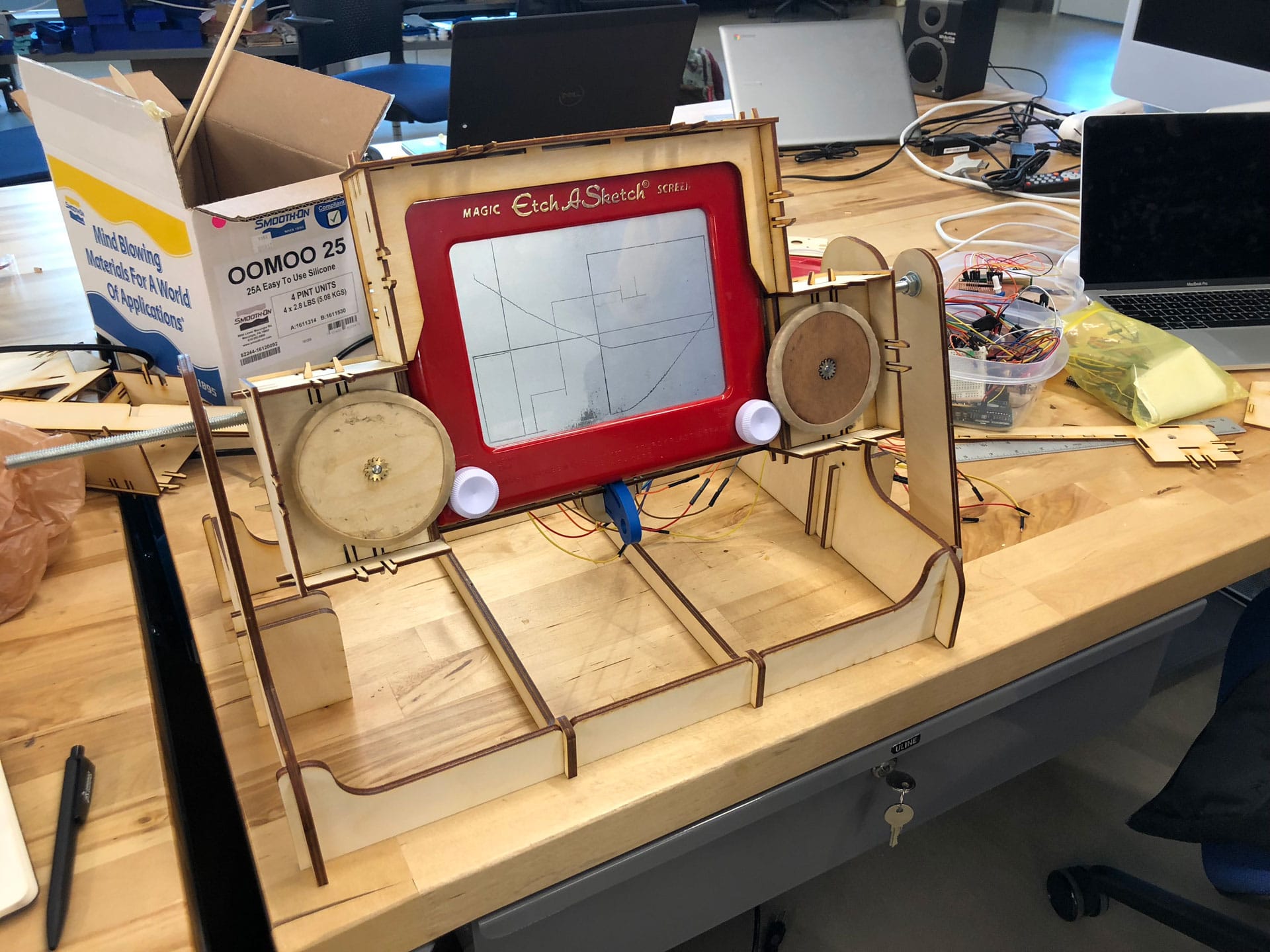
Once we had the EAS and stepper motor modeled, we started to put it together into CAD models. Sal did a nice job, and his was ultimately the design we carried forward, so I will show that one moving forward.
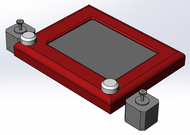
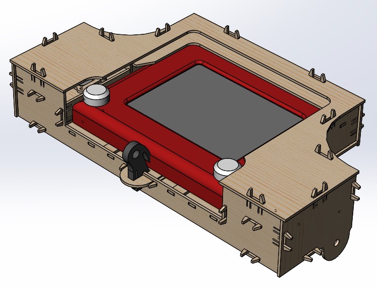
Sal's model was made from 3mm plywood with really nice snap-fit construction. It hid the stepper motors and wheels inside the case to minimize user interference with the mechanism. It also included a robust "snap key" (shown above in dark grey) which snaps into place and holds the EAS snuggly in the case and puts the requisite pressure on the knob/drive wheel interface.
Machine Design
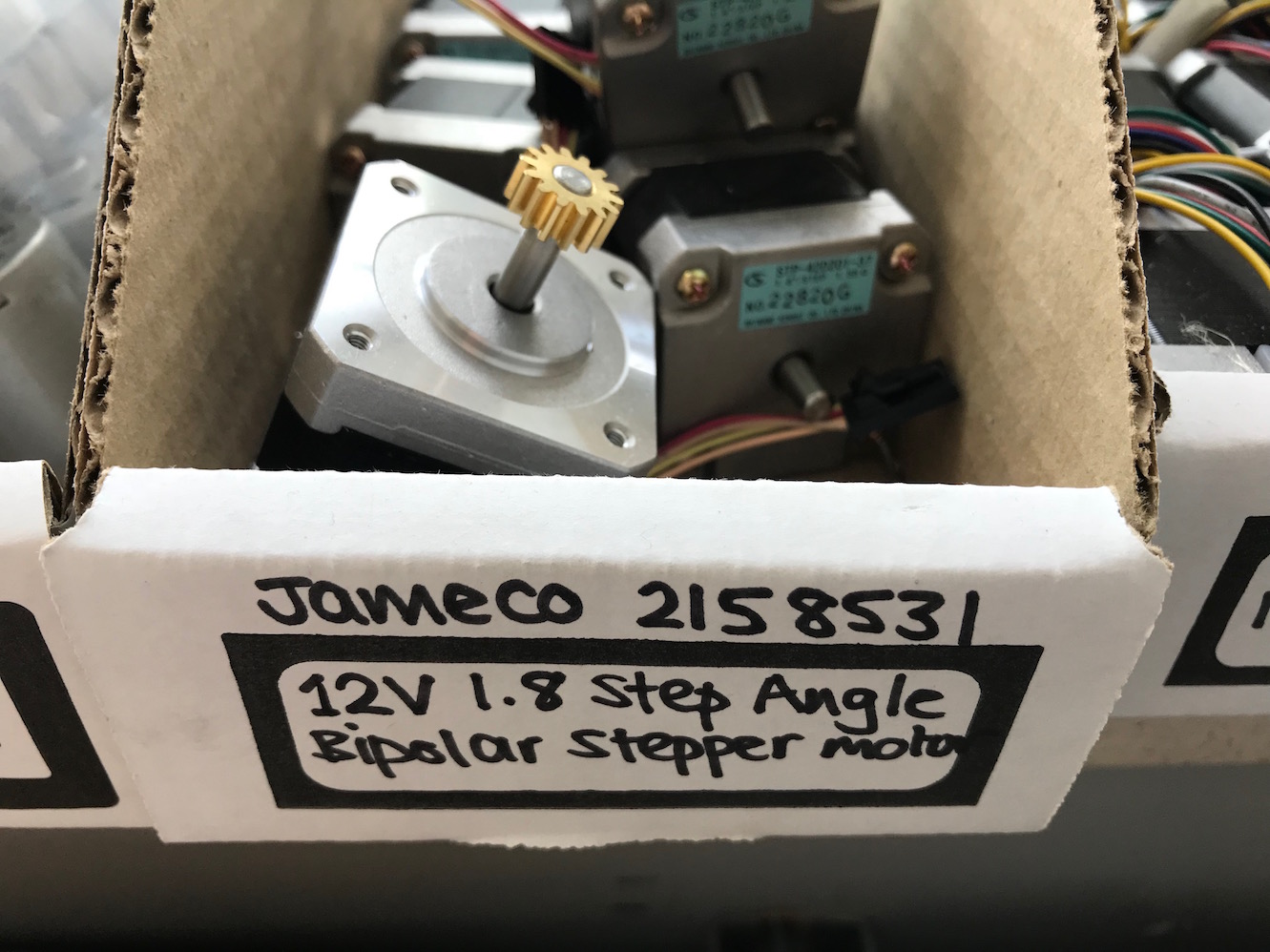
Once we had the mechanical side of things more or less ironed out, we needed to get the machine up and working, including figuring out a system for its electronic "brain". At first I thought we would have to design our own boards, so I did a bunch of research into stepper motors, how they work, the difference between bipolar and "regular" stepper motors, and the differences between 4-wire, 5-wire, and 6-wire motors. It seemed to me like a moderately complex problem to create a board that could drive 3 axes. We had bipolar steppers with 4 wires and each one would need an H-bridge. Each H-bridge requires 2 pins with PWM, so we'd need a total of 6 pins with PWM. This put us well out of reach of the ATtiny44s I had mostly been using up until this point (they only have 4 PWM pins). The ATmega328p (the standard Arduino AVR microcontroller) does have 6 PWM channels, so that might work. But thankfully, the assignment didn't require us to fab our own boards. At Luciano's recommendation, we decided to order the TinyG 3-axis controller board from Synthetos.
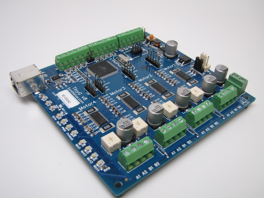
The TinyG uses at ATxmega192 as it's brain - a substantially more powerful and robust chip, even than the 328p in an Arduino. The ATxmega192 has 8 PWM channels, and has much more memory for more complex programs, as well as many other powerful features. The TinyG seems like a really nice out-of-the-box solution for multi-axis motion control, and at $130 US it's relatively affordable. I would still love to design a simple, 3-axis motion control board, and mill it in house at some point. The TinyG is actually a little overpowered for our purposes. A homemade version would potentially be simpler and much cheaper (though more work to implement, to be sure).
We hooked up the TinyG to our stepper motors for testing and callibration.
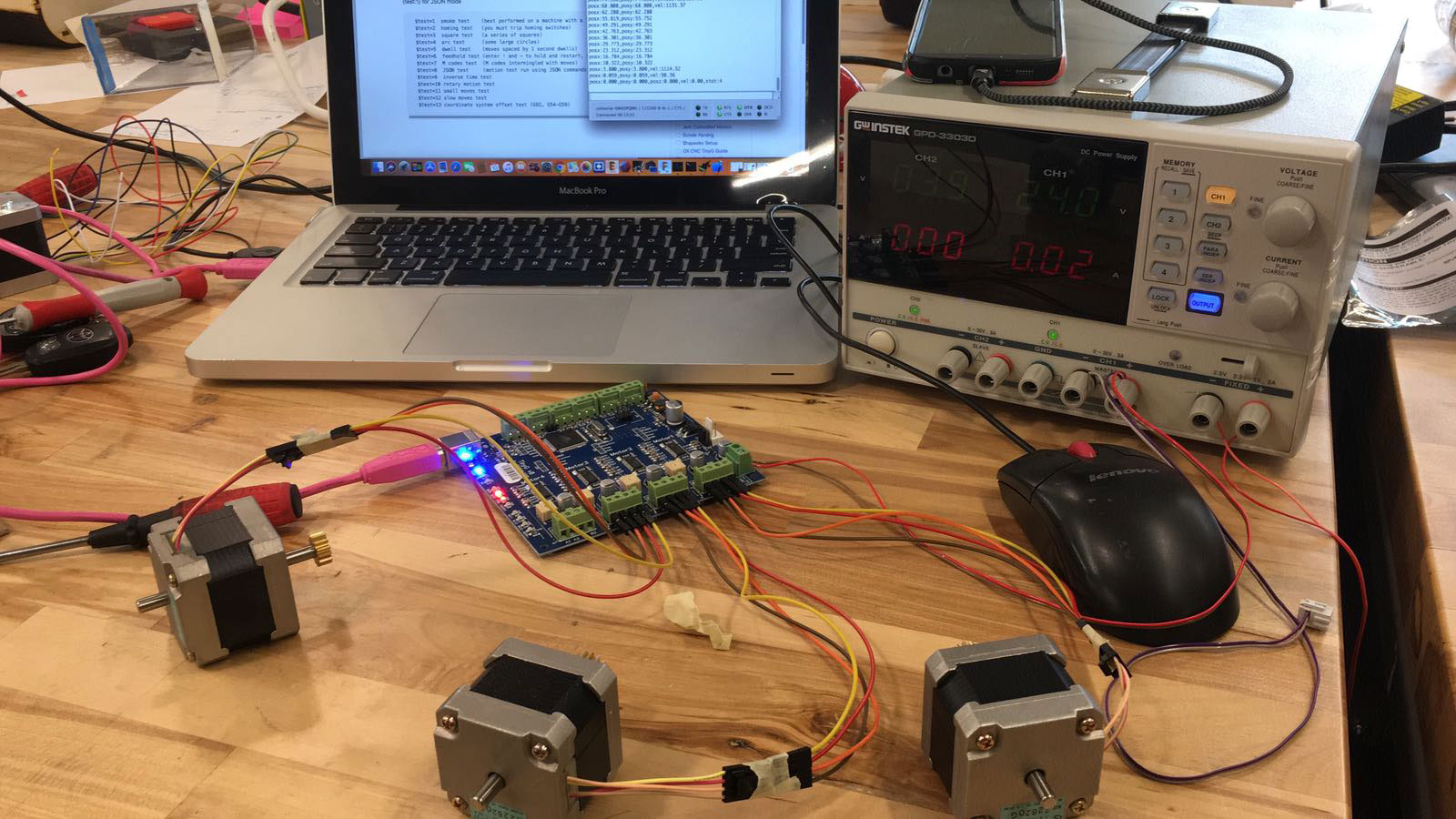
Then we put the steppers into the machine, loaded the Etch-A-Sketch, and did some testing by inputting g-code directly via serial using CoolTerm. We got some basic output working!
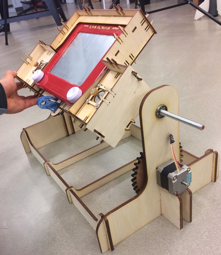
My coursemates continued the work further, getting the TinyG to take multiple lines of g-code, mounting the unit on a base with a swivel rod, mounted on skateboard bearings (which I brought from Lena Park). The final product looks pretty good, and works OK too!
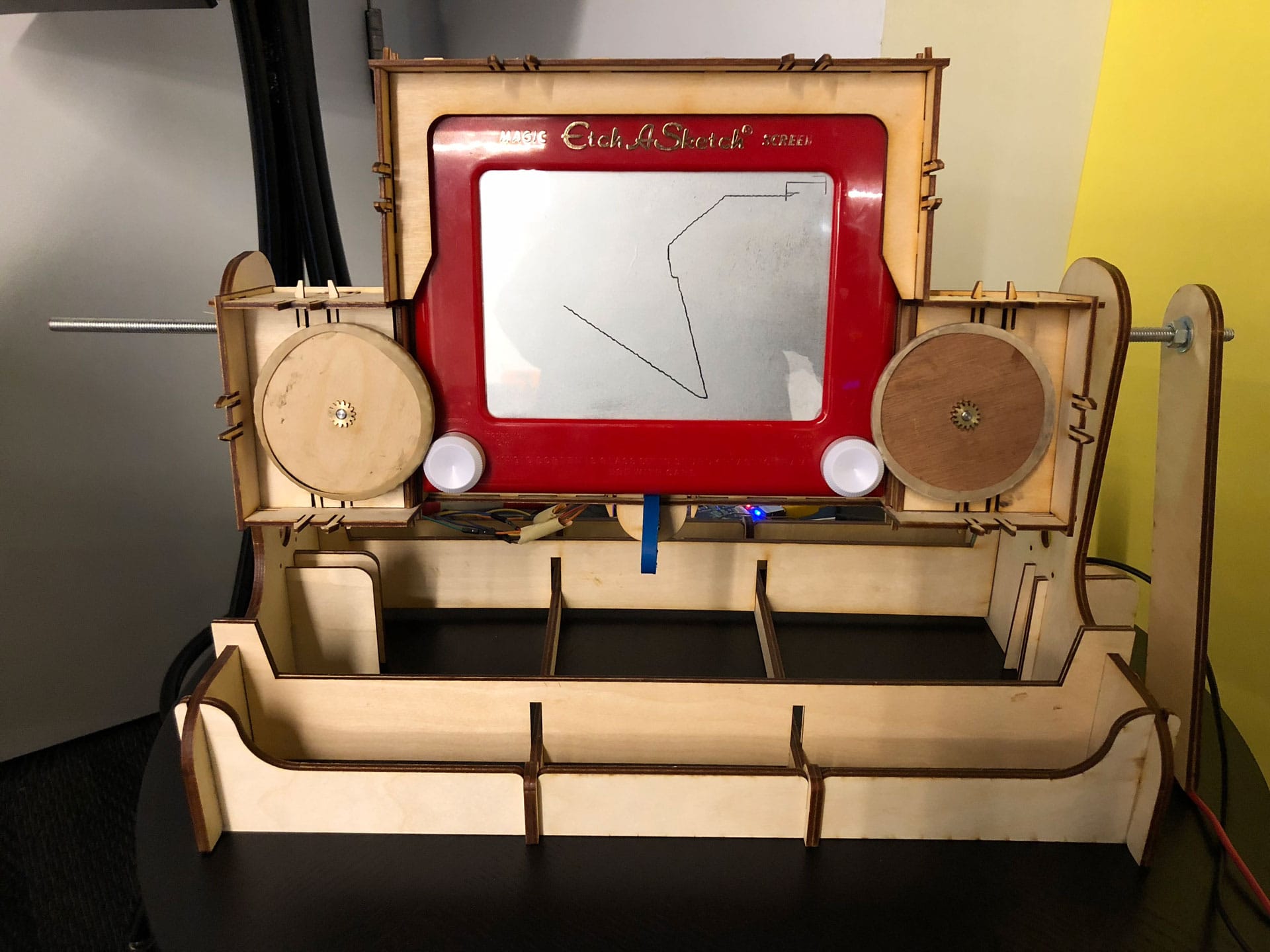
There's definitely still some fine tuning to do. And personally, I'd actually like to build a whole second machine so that I can get more experience with g-code, the TinyG interface, and finishing up the whole package. But I'm super impressed with how far we got in just two short weeks. Here's our Group Page with links to other documentation.
Design Files & Code
Etch-a-Sketch Fusion 360 file (.f3d file)
Sal's design files (.ZIP file including solidworks files)
Drivewheel file for laser cutting (.SVG file)