Assignments
Our tasks for this week are:
- Group assignment: test the design rules for your 3D printer(s)
- Individual assignment:
- Design and 3D print an object (small, few cm3, limited by printer time) that could not be made subtractively
- 3D scan an object (and optionally print it)
Group Assignment
See our documentation for this week’s group assignment, testing the design rules for our 3D printers, here.
We have several types of 3D printers available to us at Fab Lab Barcelona. Most are FDM (Fused Deposition Modeling) but several SLA (Stereolithography) 3D printers are also available.
We did test prints on several of the FDM printers to see how each handled the stress test.


Takeaways
- The different styles of printer (FDM vs SLA) require different “stress” tests. A test print that would be difficult on an FDM printer could be easy to achieve on an SLA printer due to the different technology.
- There is variation in performance among printers of different brands (and even different machines of the same brand), even if they are utilizing the same technology. The outputs of the Prusa, the Creality, and the Zortrax printers were all different despite starting with the same test file. It is always best to do a specific test part to assess the strengths and weaknesses of the printer in front of you rather than just using settings you’ve used before on other printers (although that could be a good starting point).
- There are tradeoffs in cost, print time, and print quality that need to be considered when selecting a 3D printer. Parameters/tests to characterise a printer include: unsupported walls, overhang angle, embossed & engraved details, horizontal bridge span, holes, connecting/moving parts (measure tolerance), and pin diameter.
Cura Slicer Settings
For our FDM printers, the local instructors suggested using UltiMaker Cura as the slicing software.
We have a few Creality Ender-3 Pro printers. Most of them have a 0.6mm nozzle, which needs to be reflected in the software.
PLA: nozzle temperature: 217C Bed temp: 60C
Individual Assignments
3D Scanning
Lena, Andrea, and I teamed up to 3D scan each other (and then Danni :) ). There was certainly a learning curve- with each iteration we honed our technique until we were able to reliably produce pretty nice scans of each of our faces! One person sat still in a chair and essentially got to take a nap as they were scanned, one person held the scanner, and the third person carried the laptop behind the scanner and gave them feedback about how the scan was going (if they were going too fast, or needed to change the distance, or if the scan got messed up).


The first few scans we noticed that the scan would be going well until the back of the head, at which point it would kindof lose its registration to the previously scanned section. This led to some pretty humorous double-headed artifacts. To combat this, which we guessed was due at least in part to the limitations of the scanner in scanning (shiny) hair, we changed our technique to focus on the sides and front of the face.
We also adopted a new scanning pattern methodology where the scanner would slowly rotate the sensor up and down to capture the scanee from below and above before taking a small slow step to the side and repeating the vertical sweep. In this way the scanner didn’t have to rotate horizonatally a full 360 degrees around the scanee to achieve a good quality scan of the facial features.
Another small but effective change we made was rotating the chair of the scanee so that the overhead lighting hit their face more directly and from the front. This lighting change seemed to result in better tracking and translated into a better quality scan and some of our first attempts.
At the end, each of us had a digital 3D likeness of ourselves!


I had my hair up and it was a bit difficult for the scanner to capture, but it did a good job with my face.
Bonus Scan
Later in the week I also did a bonus scan of a walnut using the RevoPoint scanning system. The Revopoint scanner we have in the lab also has a turntable attachment and stand for the scanner so you can keep the scanning head still while slowly rotating the object you’re scanning.

Scan acquisition settings include Exposure, Color scan (vs no color), and Scanning distance range (can be used to avoid including background objects in the scan). A helpful bar along the right of the scan preview window shows you if the scanner is positioned the appropriate distance from the object.


In the software after acquiring the scan/point cloud, it’s also possible to take scans of the object in multiple positions and then align and merge them together to get one closed mesh.


3D Printing
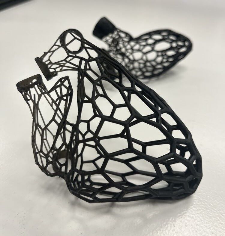
I opted to print with the ANYCUBIC resin printer since I haven’t done much printing on SLA printers. A heart, of course, but I created a complex structure which couldn’t be additively manufactured by applying voronoi patterning!
Design
My starting point for performing the Voronoi-ification was 2 smoothed meshes, representing the blood pool of the right heart and the left heart, respectively.

I played around with applying a voronoi pattern to the geometries in several programs: Rhino/Grasshopper, Blender, and Meshmixer.


I got close with Rhino/Grasshopper but ultimately opted to go with Meshmixer because I’ve used it to apply voronoi patterning to 3D prints in the past. Also I needed to work quick in order to get my design done and on the printer!
The first problem I faced with Meshmixer was that it wouldn’t install properly on my laptop. After watching several troubleshooting videos to no avail, I ended up installing it on a computer in the lab to move forward.
Once I had my geometry imported into Meshmixer, I isolated the triangles of the inlets/outlets from the rest of the geometry. I wanted to keep the inlets and outlets intact, and only apply the voronoi structure selectively to the internal surface. There’s a helpful tutorial on YouTube that I scanned through to achieve the look I was going for.

Next I needed to greatly reduce the number of triangles in that region-of-interest. I did this by selecting the internal geometry I’d separated and then Edit > Reduce and played with the percentage until I was happy. It took two rounds of mesh reduction to arrive at a geometry sufficiently reduced to give the loose voronoi pattern I was looking for.
Next, I went to the Edit > Make Pattern > Pattern Type: Dual Edges. I also opted to add a line gradient to my geometry.

I combined the un-voronoi-ed inlets/outlets with the voronoi-ified section to get one watertight part to print, and went through this process for both sides so I’d have the right heart and left heart as separate pieces.
Slicing
I combined my parts with Susanna’s since the SLA printer works by curing one layer at a time (so it takes the same time for one object to print as many objects, as long as they’re all the same height). The resin printer we have is the ANYCUBIC Photon Workshop M3 Plus. It has it’s own proprietary slicing software: ANYCUBIC Photon Workshop 3D Slicer Software. We imported our parts as STLs and positioned them on the print bed in the software. We used the standard settings for the SLA slicing software with a few exceptions which I’ll outline below.
Machine: Anycubin Photon M3 Plus Resin: Default Resin_Normal Slice parameter: Layer thickness: 0.050 mm Slice parameter: Exposure time: 1.500 s Lift Distance: 6mm

I’ve summarized a few of the key parameters/settings below.
Exposure Time
The resin printer works by selectively flashing light to cure a layer of resin, one layer at a time. The model prints ‘upside down’: where the base plate lowers into the resevoir of liquid resin, and one layer is cured by being flashed with an LCD screen under the resin resevoir. Then the base plate lifts back up so fresh resin can flow between the most recently cured layer and the LCD screen, and the process repeats as many times as necessary until the print completes. This layer-by-layer approach allows resin printers like this one to overcome some limitations of FDM printers (higher resolution, faster print times since one layer is ‘printed’ at a time).
N.B. it’s a good idea to do an SLA specific print test (can find template parts online, to test for resolution and curing/exposure time)
The default, basic settings are generally fine. However, we did adjust the Bottom Exposure Time from 23 seconds to 30 seconds, for 4-6 layers. This means that for the first 4 - 6 layers, where it is critical that the layers adhere well to the base plate and aren’t sucked off by the viscous resin (which would cause the print to fail), we let the resin cure extra long. After those early, delicate layers, the resin cure time is reduced to 1.5 seconds.
Supports

| Setting Name | Setting Value |
|---|---|
| Support Script | Light |
| Support Angle | 50 degrees |
| Anchor Distance | 2.5 mm |
| Z-lift Height | 5.0 mm |
Since it would be kindof a long print, we loaded the slicer output into the ANYCUBIC resin printer and left for the night!
Postprocessing
One of the “downsides” of resin printers are that they require postprocessing. They have incredible resolution so the print quality definitely outweights the potential annoyance of the postprocessing in my book!
When we came back the next morning, a very pleasing sight greeted us:


When a part comes off the bed it’s not fully cured and is covered in sticky resin, so you use gloves, plentiful paper towels, and a rubber tool to gently pry it off the print bed and put it in an alcohol bath to remove the excess.


Once it’s had a good soak in the alcohol, it’s time to gently remove the support material.


In my prints I had some sections of the voronoi lattice as small as 0.5mm, so the prints were very delicate (and essentially as big as the support structures!). I was able to remove the supports without too much damage.
Due to the hollow internal structure and the intricate voronoi patterning of the walls, this shape could not have been easily manufactured subtractively. Even using an FDM printer this geometry would have been challenging to manufacture additively; it truly was a great use case for the resin SLA printer!
Hero Shots!


Reflections
This was a fun week; it felt great to get that heart successfully 3D printed out of resin! I did a version of this project previously but didn’t document it, so this was a good opportunity to iterate.