
Assignments
Our tasks for this week are:
- Group assignment: characterize your lasercutter’s focus, power, speed, rate, kerf, and joint clearance document your work.
- Individual assignments:
- Design, lasercut, and document a parametric press-fit construction kit, which can be assembled in multiple ways while accounting for the lasercutter kerf.
- Cut something on the vinylcutter.
Parametric Design
The idea of parametric design is that you can define parameters which you reference in the dimensions of your design so it’s easy to make updates to your design without needing to start from stratch. It’s a good idea to think a little bit about which parameters to include ahead of time so you can build the design as elegantly as possible. You can also use parameters to define other parameters, building a relationship of dependence so that just by updating one parameter you can propogate changes through the design (hopefully without breaking anything!)
Certain softwares are built to allow parametric design, while others do not offer that functionality. Engineering softwares such as Solidworks, Fusion 360, and Onshape allow you to design parametrically. Blender and Grasshopper (part of Rhino) are also parametric, but are node based.
Laser Cutting
There are multiple laser cutters at Fab Lab Barcelona and two of them are reserved for our group to use this week.
Group Assignment
The extended documentation for the group assignment of characterizing our lasercutters’ power, speed, frequency, kerf, and joint clearance is stored on our group website.
To summarize, we split up into two groups and each group performed the characterization tests on one of the laser cutters with several different materials.

| Material | thickness | kerf (mm) | press fit slot size (mm) |
|---|---|---|---|
| cardboard | 4 mm | .15 | 3.7 |
| cardboard | 1.5 mm | .2 | 1.05 |
| plywood | 4.2 mm | .075 | 4.05 |
Note: these are starting points for the kerf, but always do a few test pieces first to ensure a good fit before cutting all of them! Also measure the material because even though it’s supposed to be a certain thickness there’s always some variation.
Takeaways
- Always do a test square first! This makes sure you have your settings dialed in so you don’t waste time and material cutting with settings that don’t work. Our raster setting for the plywood was a bit to much power/too little speed so there was a lot of burning. We could have dialed the speed up to reduce the amount of burning.
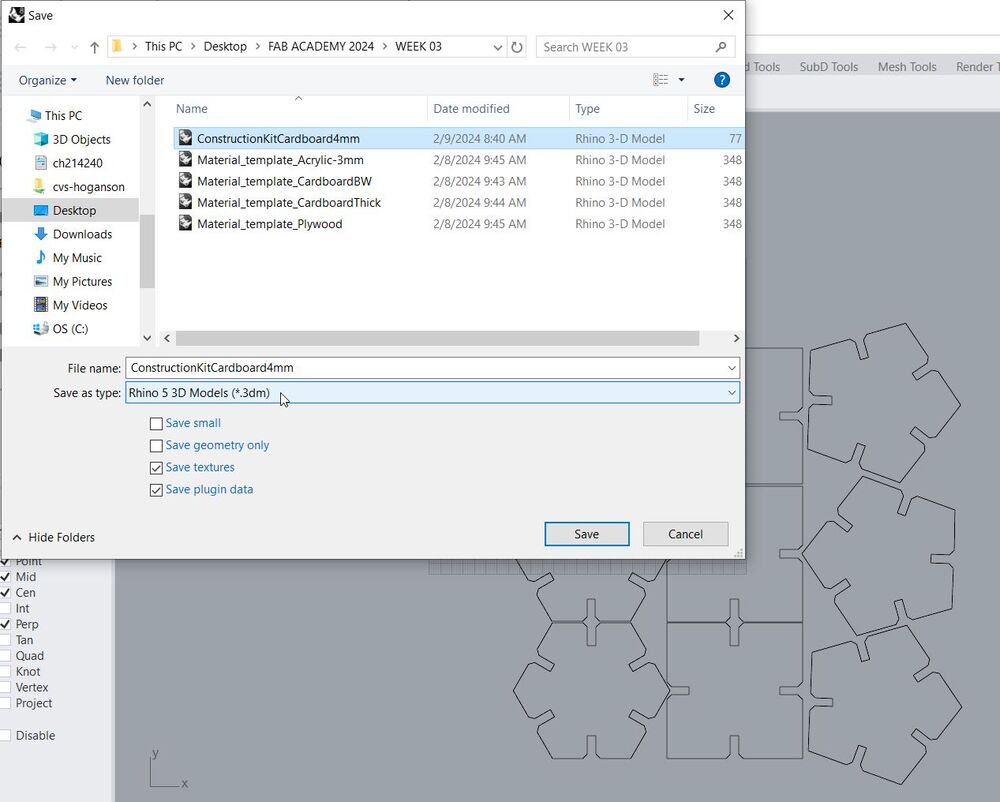
- Save files as Rhino 5 (or as DXF) so you don’t have compatibility errors with the version of Rhino installed on the computer linked to the laser.
- Smoke extraction system on, set up the material on the bed (using tape or clips to keep it as flat as possible), then focus the laser beam. If you remove the material for whatever reason and then put it back on, you should refocus again! Turn on the compressed air to keep the lense/cutting area clear and prevent buildup of smoke/heat.
- Double and triple check the power/speed settings of materials before sending to them to the printer
Operating the Laser Cutter
The workflow for operating the laser is:
- Prepare the file. This week we don’t need to worry about reserving the machines because they’re reserved for us, but in future weeks we’ll need to use the reservation system of booking time on the machines at least 24 hours ahead of using them. File preparation should be completed before the booked time so all of your time can go towards cutting. The order of operations should be raster –> etch –> cuts in –> cuts out. So a good rule of thumb is to use black for rastering, red for etching or cuts in, and blue to cuts out.
- Prepare the material. Place it on the bed and fasten it down appropriately so it’s as flat as possible using tape or clips on the edges (for this reason, if the material is warped at all place it so the center is down and edges/tips up, so you can secure those edges down.)
- Prepare the machine. Ensure the smoke extraction system is on. Focus the laser using the focusing tool. Turn on the compressed air.
- Set the cutting/rastering settings for the material, thickness, and operations (raster, engrave, cut).
- Run a test cut with a small square to confirm your cutting and/or raster settings
- If needed, adjust the settings and run the test cut again until you’re satisfied with the settings
- Position the head of the laser and file, and send to the laser cutter
- IMPORTANT Watch the laser cutter until the the job is complete. Do not leave the room or turn your back!
Notes: try to nest pieces as close together as possible, and cut on the edges of the material to save space and material.
Individual Assignment: Press fit construction kit (parametrically designed)
I decided to use Fusion 360 to design my parametric parametric construction kit. In our local class we did an exercise together to design parametric pieces. To keep it simple I’ll just use those pieces to fulfil so I can spend the rest of the week exploring the tools in other ways!


After adding a few parameters we started sketching, and using those parameters to define dimensions in the sketch


Since I’m using the thick (4mm) cardboard as my material, I set the Thickness parameter to 4mm. From our laser/material characterization experiments I know that the kerf is around .15mm. I’ll do a quick test cut with these parameters to make sure the press-fit joint is dialed in the way I want. The beauty of this method of design is that if I want to use another material I can just update the thickness parameter and see my design change instantaneously.
As a exercise I wanted to play a bit with the Configurations feature within Fusion 360. I made several configurations of the same body/component but changed the NumberSides parameter in each:

This allowed me to quickly switch between the configurations…


…and export the projected sketch of each as a DXF.

Files
- The DXF for the 4-sided piece | DXF file
- The DXF for the 5-sided piece | DXF file
- The DXF for the 6-sided piece | DXF file
- The Fusion360 file | F3Z file note: this is a fusion archive folder that needs to be uploaded into Fusion360; I couldn’t export as a standard fusion360 file because of the configuration.
Then I imported all of the DXFs into a Rhino file, duplicated the pieces as many times as I wanted so I’d have a few of each, and nested them together.

Important: Save As Rhino version 5 so that there’s compatibility with the computer connected to the laser cutter.
On the computer connected to the laser cutter, I went ahead and opened my Rhino file and printed to the Laser Cutting software.

Laser cutting:


Hero shots:


Vinyl Cutting
In keeping with the theme of hearts, I did a quick google search and found a black & white image I liked.
Silhouette cutting
I decided to use the silhouette cutting machine since I haven’t used it before (I have used a Roland vinyl cutter before).

First step is downloading the free software from the Silhouette Website.
I’d found an image of a heart with spirally designs on the web and imported it into Inkscape. Once in Inkscape I performed the Trace Bitmap operation to vectorize the image. Then I exported it as a PNG.
File
- The Inkscape file for my heart sticker | SVG file
I imported the file into the Silhouette software and made sure to select the appropriate material from the list of materials already in the software. I was using a matte black vinyl.

With the material added to the machine (via a sticky board, which allows you to use smaller pieces of vinyl), I did a quick test cut to confirm my cut settings before moving the tip of the blade (via the arrow buttons on the panel) to set my zero point.
And then I sent the file to the machine and watched it do its thing! Because the piece I was using was rather small, the size of my sticker was limited to around 2". This meant some of the lines were quite narrow, so it was a bit of a stress test of the vinyl cutter to see how fine details I could cut!

The final result/Hero Shot:


Reflections
Parametric modeling is a very powerful tool in order to construct robust and responsive designs! It can take a little more thought upfront to select and define the set of parameters, but the result is a model/design which can update in seconds when one parameter is changed. The payoff on the backend seems well worth the upfront effort.
I’ve used both a laser cutter and a vinyl cutter before and it was nice to play with them again.