
Making XY Plotter Machine
WEEK15&16: MECHANICAL DESIGN AND MACHINE DESIGN
- For machine design group work we have decided to make 2 axis machine, which can draw as per Gcode and also at later stage it has replaceable/multiple end-effector such as pen or cutter.
- Below is one page machine making slide and video of machine making process and journey.
- Complete machine design docuemntation is on our Lab website
ASSIGNMENTS:
- Design a machine that includes mechanism+actuation+automation
- Build the mechanical parts and operate it manually
- Actuate and automate your machine
- Document the group project and your individual contribution
My roles and individual contribution to make machine
- My main role for these two weeks machine design assignments are,
- Project Management - I took responsibility to manage and lead the group work in terms of time line, planning, execution and bring group to decision.
- Procurement and Inventory BOQ- I have made it sure that all necessary items needed to make machine reach to lab on time as per our requirement including parts and raw material.
- 3D Printing of parts - My fablab machine requires certain calibration to work and print consistently, so I took charge to slice the design files with right layer resolution, print speed, and infill, etc and print it in machine.
- Making pen end-effector - End effector requires to lift pen and up and down, I have done that with servo motor and spring force.
PROJECT MANAGEMENT
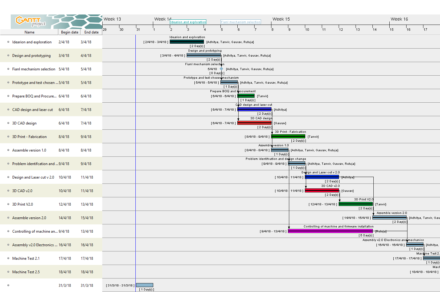
- For this I have used Gantt project, an opensource software for project management. Its also provide Gantt chart and PERT chart to export as pdf.
- Its very useful, as it helps to add tasks and respective resources, also it provides predecessor which make sure next task only can be started if previous one is being completed on time.
- This helps for spiral development of project and good time management.
- Mainly we started with ideation and prototyping to final project.
- Complete Gantt project report can be downloaded here
- For better view, complete Gantt chart can be downloaded here
- For better view, complete PERT chart can be downloaded here
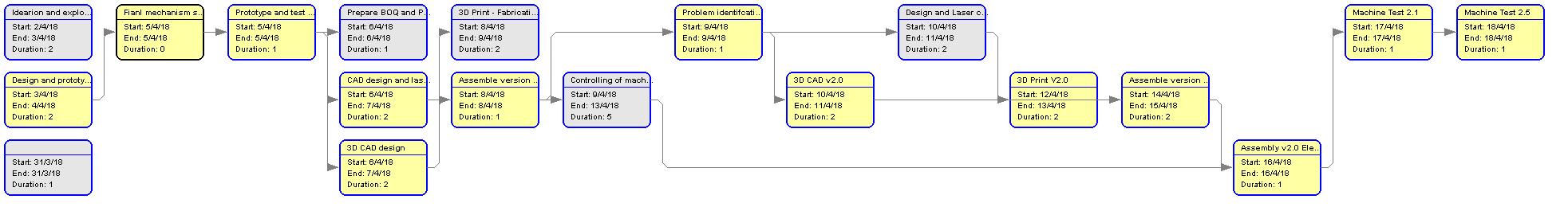
PROCUREMENT OF INVENTORY
- As reflected in Gantt project that I have started making component list once we finalized machine mechanism and first version design.
- So I took basic design reference to get dimension and specification of parts I have to procure.
- Same time also think about joinery and fasteners requirement for assembly along with motion transmission elements. For motion we have used NEMA17 bipolar stepper motors.
- So, basically it was two type of components which was mechanical and electronics.
- Following is Bill of Quantity which I have prepared for procurement.
- FComplete machine BOQ is here with local resources nearby to FabLab CEPT
3D PRINTING OF MACHINE PARTS
- For 3D Printing I have to manufacture basically two different assembly parts. 1) Central bearing and belt holder and 2) End-effector.
- For central assembly parts design prepared by fellow academy student Gaurav. Once he gave me files I took it for slicing.
- For this week's 3d printing I have used newly purchased Flahforge dreamer machine at FabLab CEPT.
- Flashforge machine used Flashprint software, which can be downlaoded for free.
- Slicing of top central part
- PRINT PARAMETERS
- Layer height - 0.10 mm
- Shell thickness - 2 (0.4*2)
- Print speed - 50mm/s, 60 mm/s (travel)
- Infill - 20%
- Layer height - 0.10 mm
- Infill - 20%
- Print speed - 50mm/s, 60 mm/s (travel)
- Slicing of bottom central part
- Printing with PLA material in left extruder in Flashforge dreamer machine
- Printing with PLA material in left extruder in Flashforge dreamer machine
- Printing bottom part with same material.
- Redesigning and printed parts for assembly version 2.0
- Assembly of 3d printed parts as central motion transfer carriage.
END-EFFECTOR - MAKING PEN HOLDER
- For our machine first end-effector we wanted to make pen holder which can draw based on given Gcode to the machine.
- In order to do so, basically I have to lift pen up and down for travel and drawing respectively.
- One way to do so is with stepper motor and attach rack and pinion type of arrangement, which on rotation of motor moves pen up and down.
- Another way to do so is with micro servo motor which rotates at certain angle and lift pen up and it can go down by may be spring or magnetic force.
- I chose to go with servo and spring because its light weight and comparatively cheap and simplified mechanism.
- Y+ rod and belt holder, and pen holder parts.
- Design reference and files were taken from henry arnold
- Assembly of 3d end effector parts with spring looks like this.
- End effector functionality with servo and spring force.
FINAL MACHINE AND VIDEO
- After all work and iterations in group work final machine looks like this.
- Here below video is complete machine making process and working video.
- Here below video is complete machine making process and working video.
FUTURE SCOPE AND AREA OF IMPROVEMENT
- There are certain areas where this machine can be improved for consistence functionality, which I would like to mention here, so further development can be initialized.
- Y- base support
- Currently Y- end part which comes at opposite side of end effector, is in air. Over a time this can be gone under cantilever bending. Here we can add drag wheel or roller to balance weight distribution and makes machine sturdy.
- Belt tension tightener
- In our machine we have used belt and pulley system to drive motions. I have seen that after certain time we have to tighten the belt if we run machine continuously for certain duration.
- If we can design and fabricate belt tightener it will be effective for consistence motion transmission
- Universal plug and play end effector
- If we can design an end effector holder which allows to accommodate different types of modules to fit and function it would add extra features to the machine.
- This reference we may take from robotic arm, where circular plate allows to fit and change different end effector to it.
- Image is from abb robot product specifications
- For complete machine documentation and original file, go to FabLab cept website
Go to Week 17
Go to Weekly work page
2018 | Tanvir Khorajiya