01
03
06
week 02 | computer-controlled cutting
07
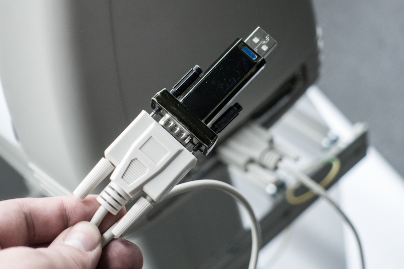
One of the two assignments for this week was using the vinyl cutter. Due to the problem that nobody really used the Refine MH721 since it was bought (only Windows driver, chinese software), I tried to pass this assignment with Christoph together. After we were not able to get a Unix compatible driver for the USB-Serial converter in this cutter, we decided to use a regular external FTDI USB-Serial converter.
08
10
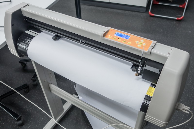
Due to the problem our vinyl cutter uses the old DMPL protocol, we were not able to use FabModules directly. So, we decided to use InkCut as InkScape extension.
11
12
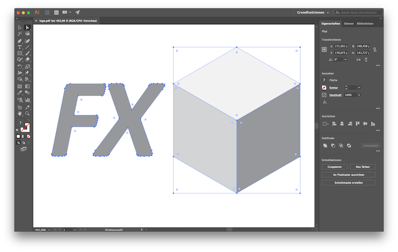
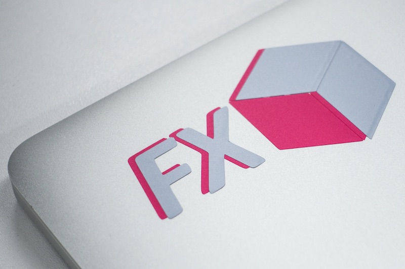
The design I used to cut, is my actual own company, called fxbox UG, logo, which was made years before in Adobe Illustrator.
Download my vector file as PDF
Download my vector file as SVG
13
14
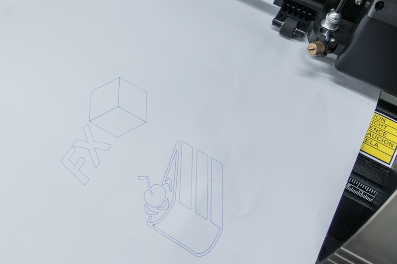
After we noticed several problems with InkCut e.g. there is no option for transformation command and only reads paths, we had success. It ended up in sending our cut jobs via bash and cat. Sending the cut job via bash and cat to the vinyl cutter.
15

16
To check and verify the function, we used the included pen instead of the blade first.
17
18
Success. :)
19
This is the point where we decided to use vinyl. After some minutes blade calibration, we got these nice, exact and not too deep cutted vinyls.
20
21
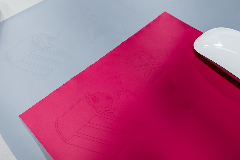
After some matrix stripping (I hope this is the right discription!?) and adding some transfer foil, I sticked my vinyls onto my MacBooks lid.
22
23
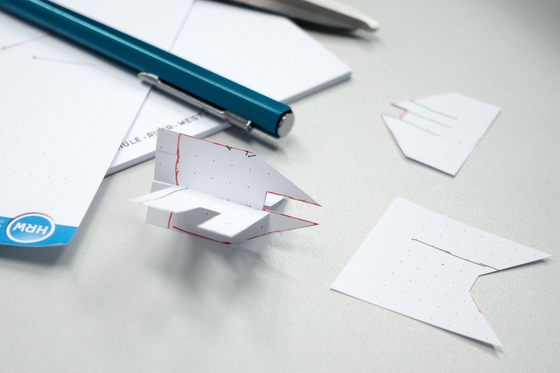
The second assignment for this week was to design a parametric press-fit cardboard construction kit and cut it on the laser cutter. So I started using some pens, paper and scissors before I tried to design the diffent parts for the kit.
24
25
After some tests and trying around, I had to test the joint mechanism. I decided myself to use a simple press-fit joint without any chamfer - just fitted, with a parametric overlap onto the next part.
26
27
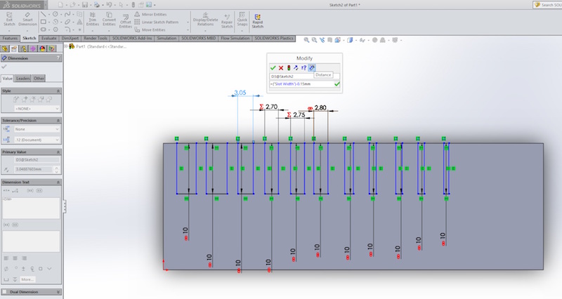
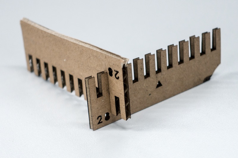
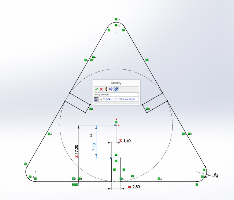
The next step I had to do, was evaluating the cutting size of our Zing 6030, so I designed a parametric testing comb, which is called Kerf test.
The slot above the triangle is 2.8mm wide, which is the thickness of my cardboard. The slots scale up and down in 0.05mm steps, so I was able to test my press-fit construction in a range between 2.55mm up to 3.05mm.
I decided to not use chamfers after some testing around, to gain the maximal connection strenght against torsion and loosening. Chamfers are nice to fit parts easier together but also weaken the connection.
I linked the different slots, which allows you to change the slot dimension but hold the 0.05mm spacing. As you can see, the perfect press-fit joint was reached at 2.6mm. Linking dimensions is SolidWorks is very easy. Go into your sketch, make a right click on the dimension you want to link, then enter a name for this value and click on ok. There is even the ability to make a equation with these linked dimensions/values to make driven dimensions.
This is helpful to make a (nearly) complete parametric model.
28
29
30
Download my laser test joint model file as SolidWorks Part
Download my laser test joint model file as STL
31
After evaluating the laser beam, I was able to construct my construction kit out of cardboard. As material (even for the laser test) I chose cardboard boxes from Ikea. They are very cheap and you don't buy too much material. The unused boxes can still used as storage :)
32
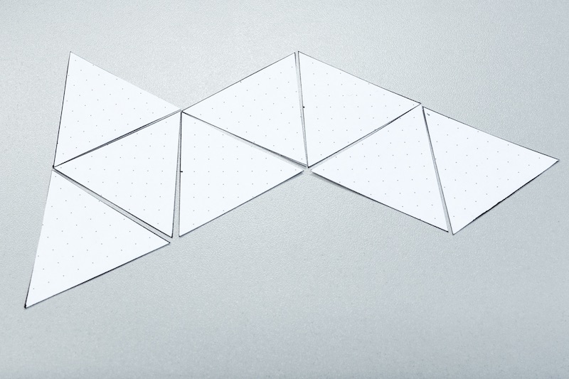
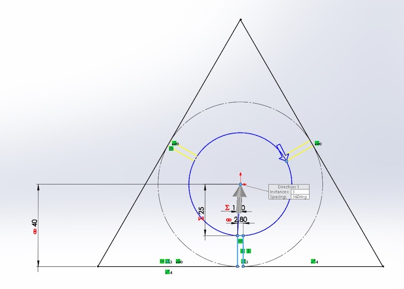
First, I started with my main part - the parametric triagle. After my paper tests I had a rough idea which sizes and ratio I wanted to use. It ended up in a size of 40mm from middle to middle. It's equal if you use the triangle main parts or the octagonal connectors - every time (until you scale my files..) you get 40mm. After scaling the parts, I rotated the slots in SolidWorks.
33
Download my CCK triangle model file as SolidWorks Part
Download my CCK triangle model file as STL
34
Download my CCK joint model file as SolidWorks Part
Download my CCK joint model file as STL
35
36
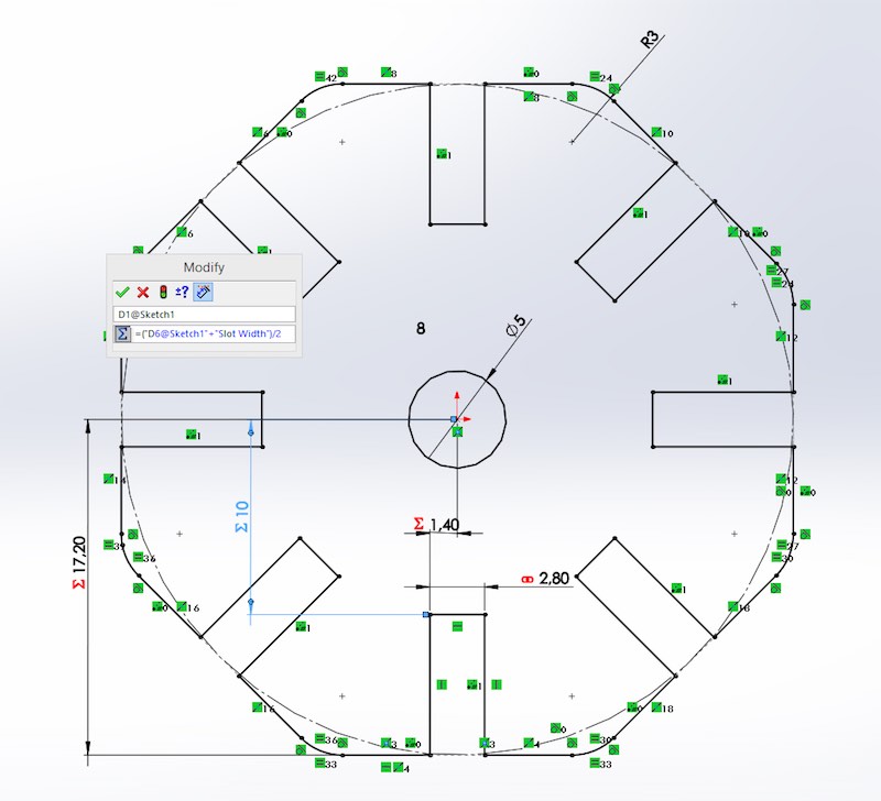
To get a full parametric part, I had to link all the dimensions. Only the rounded edges are not linked. I wanted to prevent that different parts (equal if main parts or connectors) collide in the middle, so I subtracted the material dimension(parametric!) from the over-all size of the part.
37
38
I wanted to ensure that the distance between the slot and the middle is in every situation the half of the distance between the mid points of both connected parts, so I added the material thickness to this dimension and divided it by 2.
39
40
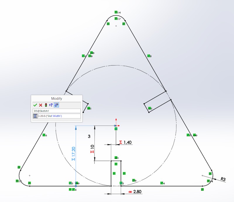
I had to do the same with my octagonal connector, which is mathematical based on my triangle main part. First, I rotated the slot sketch to duplicate them. Then I created some values like the parametric slot width, which drives the other dimensions like the outer part dimensions. The middle to slot length ratio is even fixed by linked dimensions. The over-all dimension is calculated by an equation.
41
42
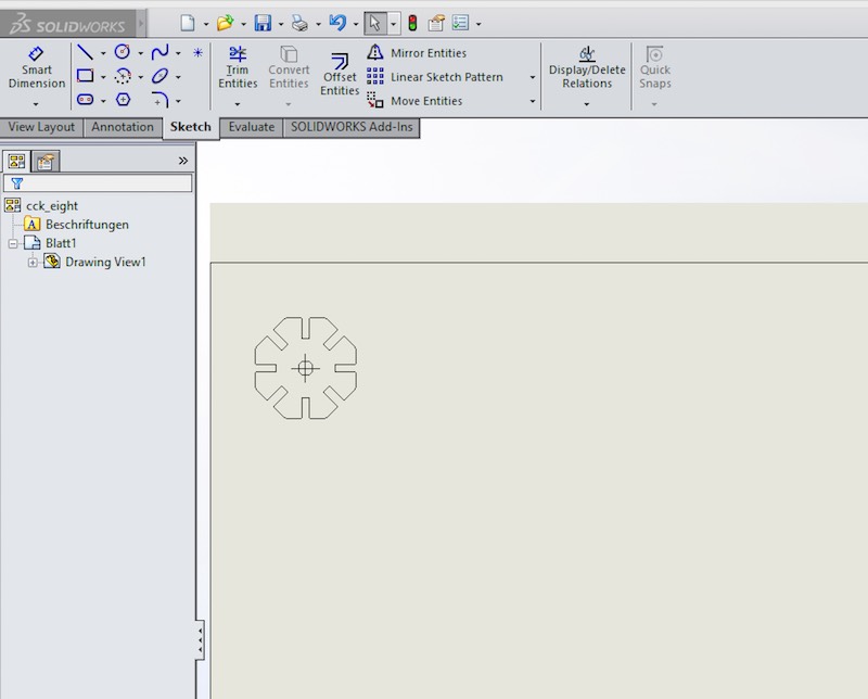
To get my model files into our lasercutter, I had to prepare them a bit. The easiest way is to generate a technical drawing in SolidWorks. I usually set the drawing sheet dimensions to the normal Zing 600x300mm. There is one thing which fails several times when somebody does not pay enough attention: scale. Scale the drawing by hand to 1:1, then insert a topview of your model and save this drawing as PDF.
43
44
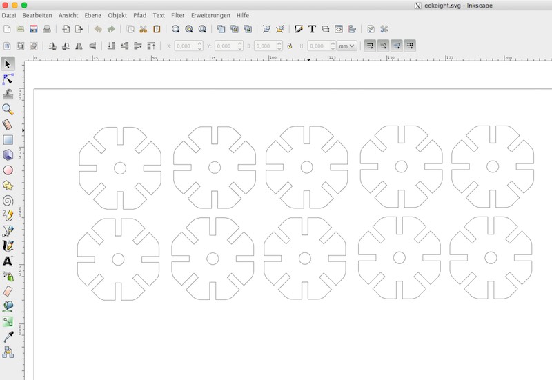
Before the smokey, smelling, cardboard destruction phase, I had to panelize my different parts to generate a SVG file. I used Inkscape this time.
45
46
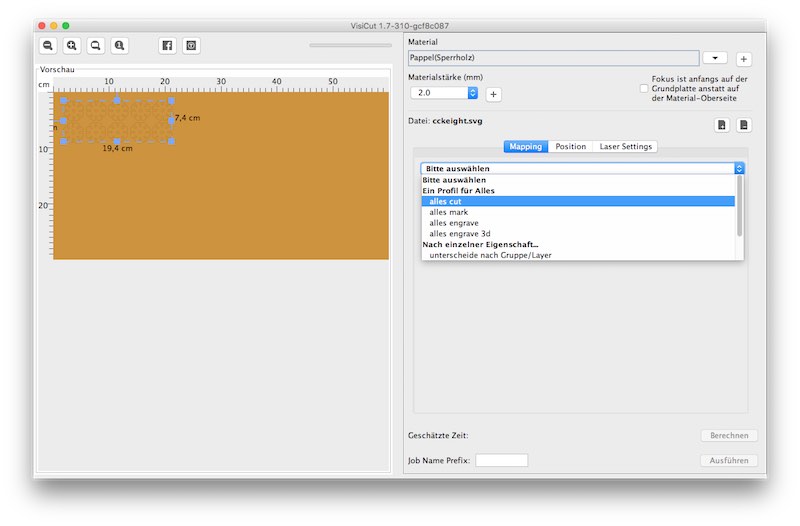
Due to the problem Epilog has not released a OS X driver for our Zing laser since years, we're using VisiCut, which is a very easy to use and smart alternative multi platform program. Instead using different colors, it uses different layer to differ between cutting, different values etc.. VisiCut even allows to use a camera to align your prints on the grid when you use used material to reduce waste.
47
You have to import your SVG file with a left-click on the import button. Then you have to select the option for the imported layer. In my case, I wanted to cut everything.
48
49
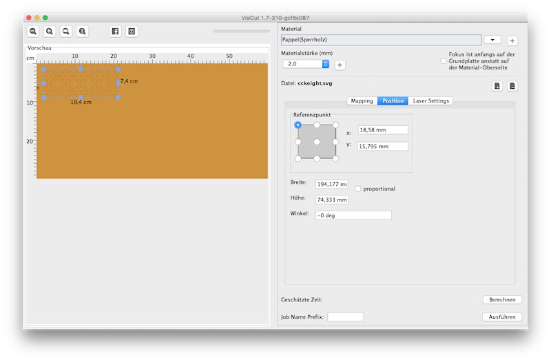
The second step allows to align your model on the cutting grid by hand.
50
51
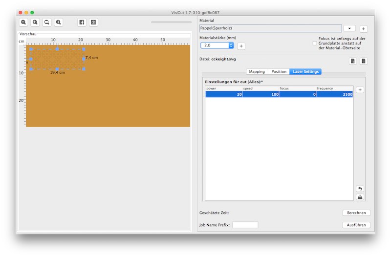
The third step is to select your material (even the thickness for auto focus) and send the job. Due to the fact I've never cutted this material, there was no preset. So I had to try different values for power, speed and freq. With 20% power, 100% speed and a frequency of 2500Hz, nothing was burnt. These values gave a absolutely clean cut. Due to the problem that we don't have the original cutting grid from Epilog and VisiCut does not offers the option to cut from inner to outer, my holes were charred and not cutted. *sigh*
52
53
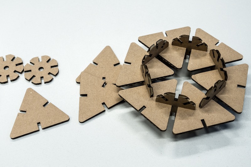
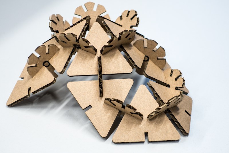
And here is the result! :)
54
55

This work by Daniel Bruns is licensed under a Creative Commons Attribution-NonCommercial-ShareAlike 4.0 International License.