I redid this assignment in 2018, as I wasn't able to finish it in 2016, and didn't really want to go on with the old results. So, look below for this year's attempt. The old stuff stays in here for future reference, and as a reminder of ye good olde times.
Week 11: Making a Mess
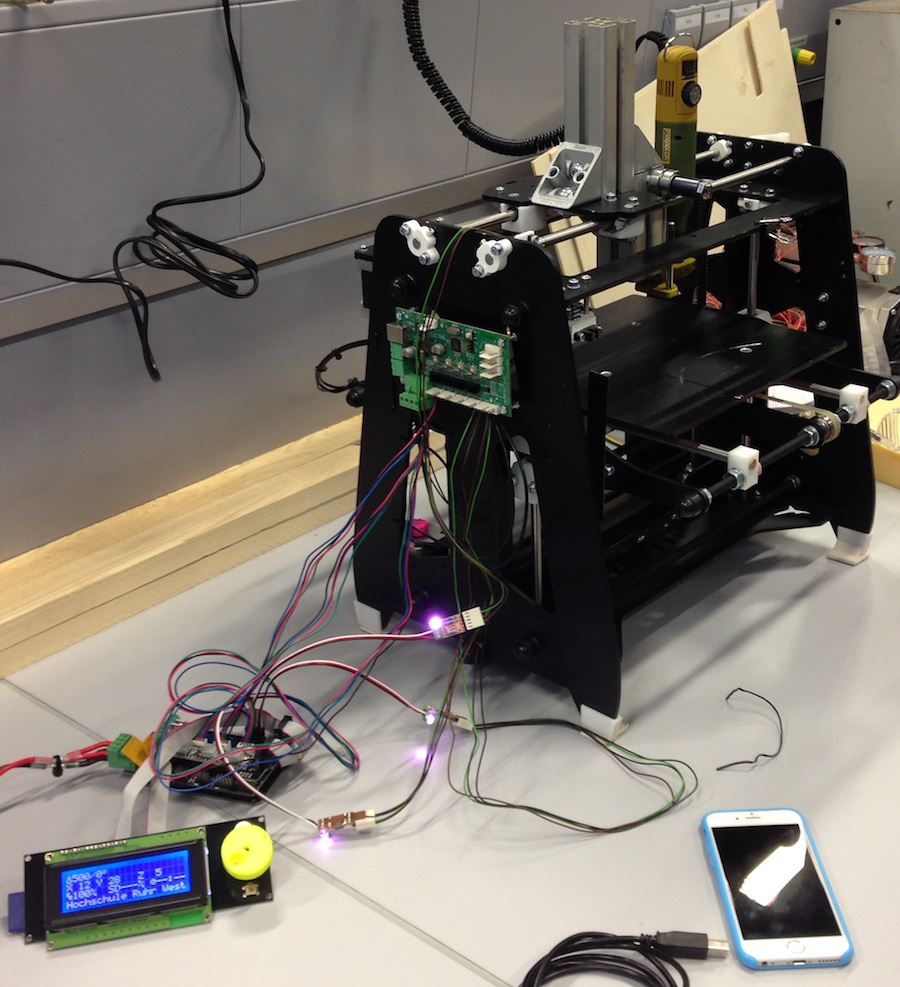
Due to work troubles, I couldn't go to Kamp-Lintfort to mill a mold, and Daniel couldn't, either. So, we built a mill. From a 3D printer. And tried to get it to run with fabmodules-generated G-code.
It works surprisingly well...
Lessons learned, so far:
The online fabmodules crash when reading one of our .stl files
The older, offline fabmodules are a lot nicer to use, but segfault when trying to calculate milling tracks for finishing
Generating a .png in the compiled fabmodules and loading that into the online version to generate milling tracks there works
It's a royal PITA to have to enter every single setting every time you try something, as the online version doesn't save settings
The G-Code generated by the fabmodules is so broken you have to massively tweak it before use (just "Z5.0000" on a line is not a valid command, "F1500.00" isn't, either... Might be the same problem the guys with the othermill encountered a few days ago on the mailing list?)
Our Poor Cat's Mill is losing steps in the Z-axis in some situations, we have to fix that ASAP
It's impressive what a firmware not made for the job (Marlin, in our case) can still do
An industrial grade vacuum cleaner is a blessing
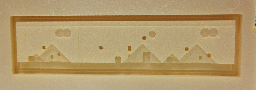
The results are quite nice for the parts without lost Z-steps (Daniel's test part, as mine isn't done yet):
Sadly, there is a lot of work left to do in here...
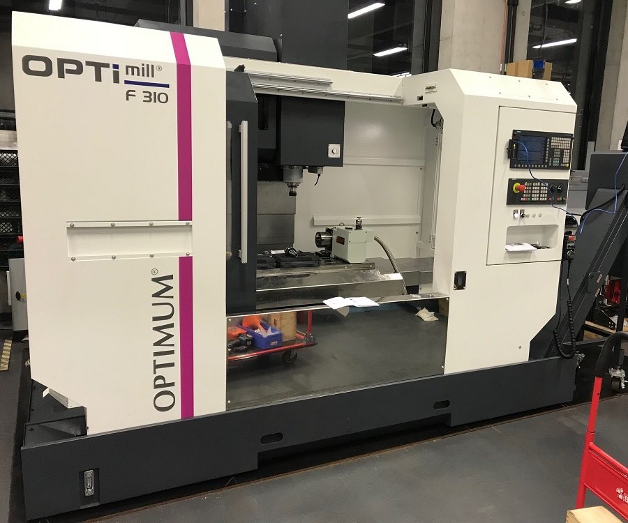
It's 2018, and while the Fablab still has no working mill to use, I do have access to one. Not on my own, as it's a real machine and not a toy, and I'm not a regular user. But I can get access to it, big thanks to Prof. Seabra and Daniel from the Technical Centre for Thermal and Mechanical Process Engineering:
Given the circumstances, I will not be milling anything from wax, as it could react with the coolant in the machine and lead to a very expensive and very hard to clean out problem I don't want to be responsible for. I will also not mill anything from plastic - It would be interesting to try, and we will try at some point, but I couldn't get any piece of millable plastic large enough in time. So, I will mill a mould from aluminium, which is a bit easier to handle (the piece of stock I bought is still almost 3kg, a piece of steel would be a lot heavier) than steel.
The Object of Interest
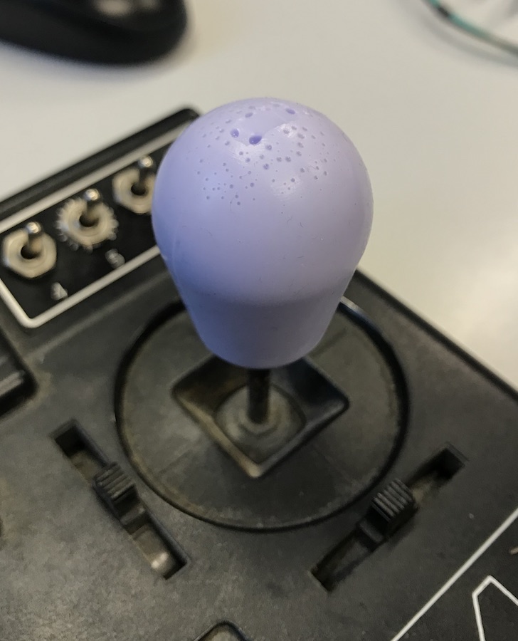
For this assignment, I want to make something pretty mundane - New grips for a small joystick. It's loosely related to my original final project (which I will still build, just not during fabacademy), as it's the kind of joystick I want to use for the placer, and a few other machine ideas:
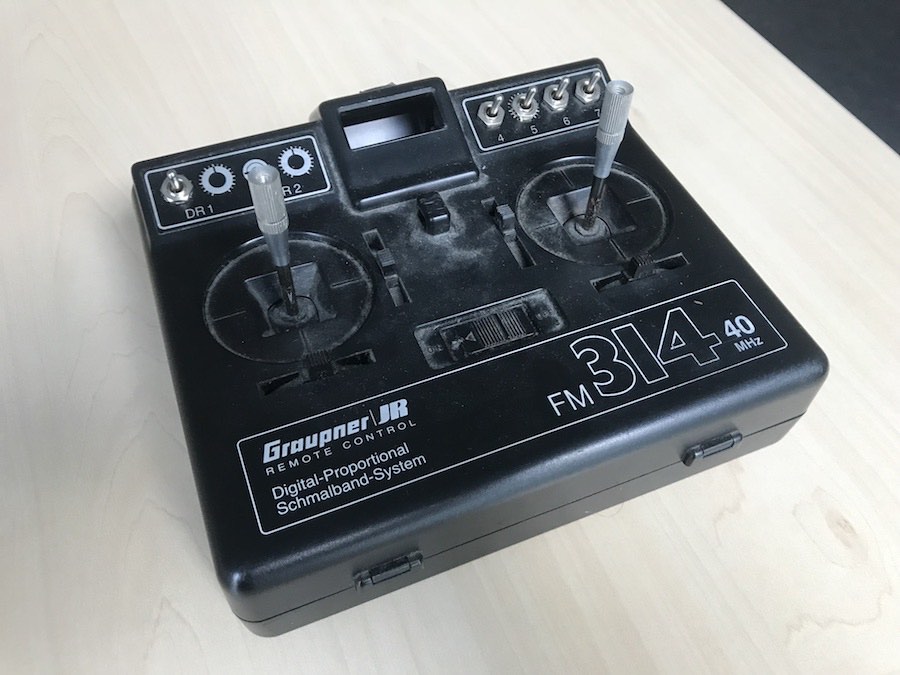
Old remote controls are extremely cheap to get, as nobody really wants them any more since the hostile takeover of the 2.4GHz systems. I don't want one to use it, either, but the joystick modules in there are usually really good (as opposed to a lot of newer systems), not only electrically but also mechanically, so they are a really good base for my own input devices.
Fun fact: You can buy the exact same modules as industrial joysticks, and they are still being made, for around 200€. A used remote is around 1/10th of that, and has two of them...
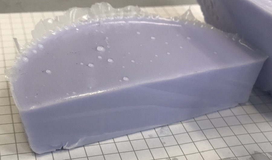
So, I really like those little sticks, but what I really don't like is their tips - They end in rather sharp-cut "crowns" of metal teeth, which is great of you're standing outside in the rain with thick gloves on and still want to have precise control. It is not great, however, when you have the joystick integrated into a panel and want to blindly grab there with your bare paws... So, I want to have a rubber grip for them. There is a lot of soft casting silicone left at the lab, so that's a match. The test cast with it looked good, too (those drops are water from cleaning it):
I would have liked pink silicone better, but that is actually hard to get if you don't want to mix the colouring yourself.
Designing a Mould
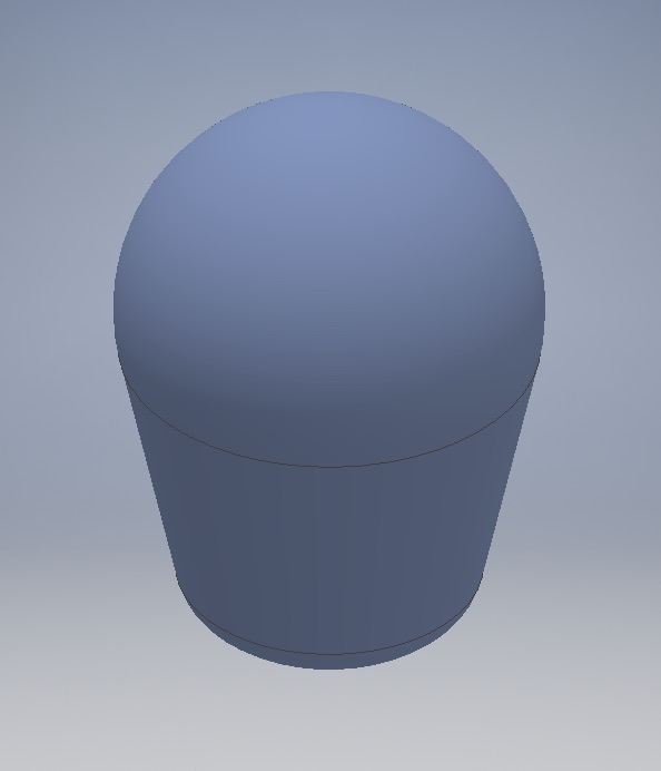
Designing the part started, in this case, with an idea and callipers to get the measurements. The form is really simple, too: A half dome on top, a slightly tapered body below and a flat bottom with a hole for the stick in it. I measured the original grip of the stick at 8mm, estimated that a 30mm diameter grip would be really chubby, but nice to grip (when you have your palm on a panel and want to just carefully move the stick with your fingers). That set the dome radius, and the rest was drawn by how it felt right:
I also rounded off the edge of the bottom side, since we only have a ball end mill with a radius of 3mm for finishing:
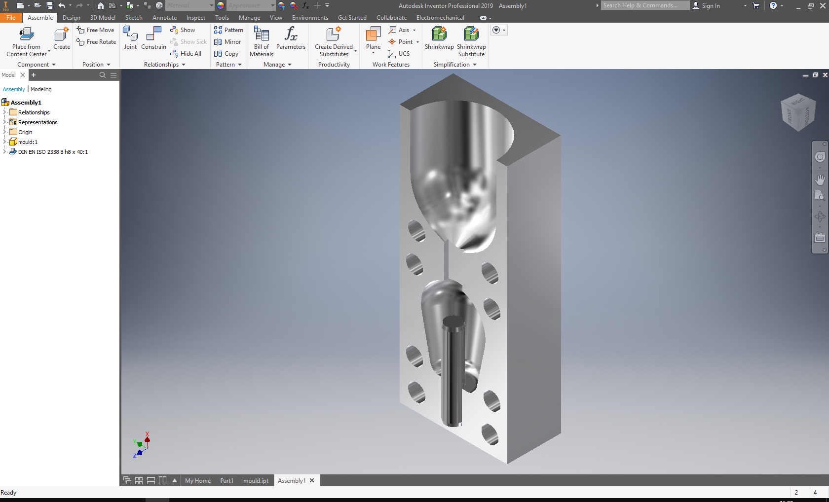
I used Autodesk Inventor to model it, as that is what I'm most used to.
Putting a mould around that design would be possible in a number of ways, and, depending on the method of casting used, most of them are not very sensible. I mainly considered two versions:
A two-piece mould that separates in a plane horizontal to the part, at the thickest point
A three-piece mould that separates in a vertical plane, with an insert for the centre hole
The first version would have had the distinct advantage of having less parts, and the inflow channel could have been hidden in a spot low at the side of the grip so its remains are less visible. It is a nice, simple concept. I didn't do it like that, though, as the bottom part would have been really deep and hard to machine - down to being impossible with the tools we have. I didn't want to buy a 100€ tool just for that.
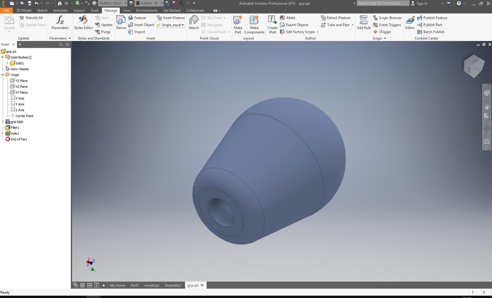
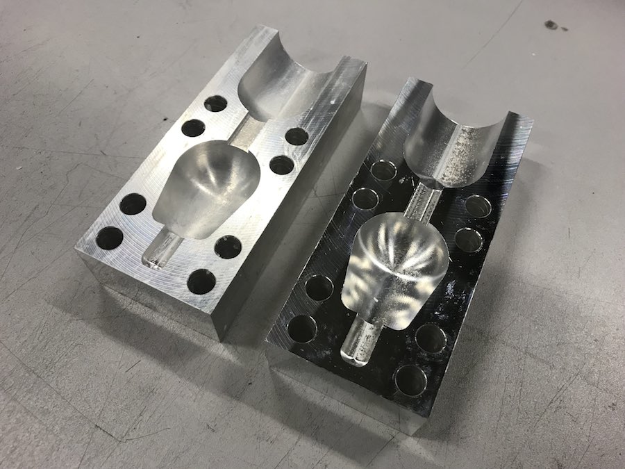
What I did draw was the second version. The inflow channel is in about the most visible spot possible - right at the top of the grip. A good, sharp knife should solve that problem, though. The mould gets simple that way, though, and a lot better to machine. I drew one symmetrical mould half, which has, of course, to be milled twice:
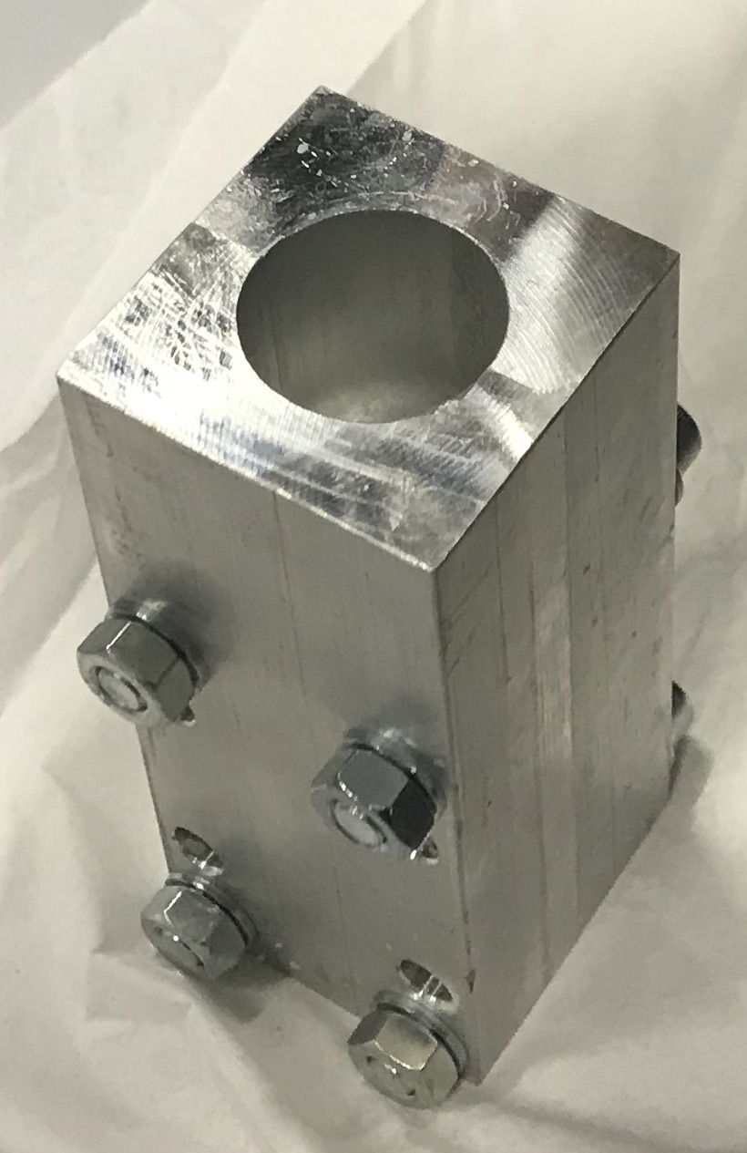
The third part of the mould is a simple cylindrical dowel pin of the same type I use to align the mould parts:
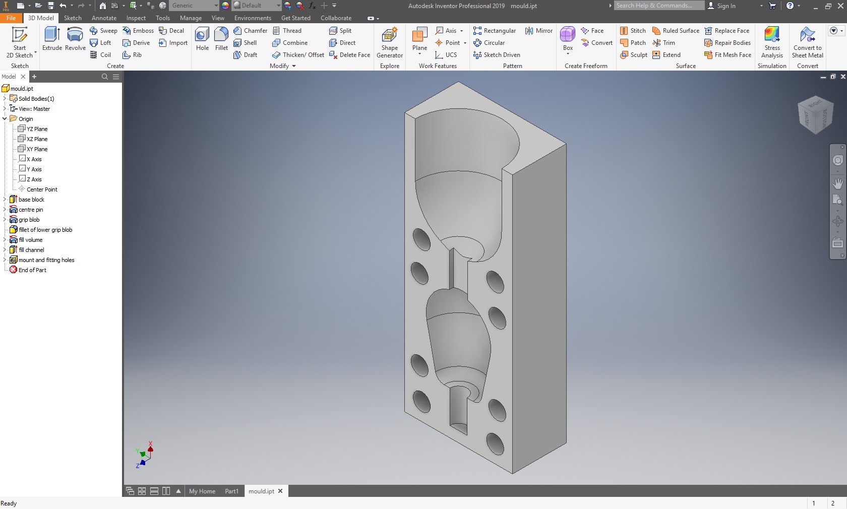
Two of those eight holes in each half are used for alignment, four for pressing together the parts. Having M8 screws in there should be way, way more than enough to hold the parts together tightly.
At what will end up the top end of the mould, I also added a rather large funnel for the silicone. I hope to be able to just cast all the silicone I need into there, then have it slowly drip into the actual mould from there - the channel is rather tight (to be easy to cut off).
Milling, Part 1: CAM
From having a model of the mould, the CAM system will bring you to an actual set of instructions for the machine. We use Autodesk HSM Ultimate here at the moment, and it seems to work, albeit a bit finicky at times.
The very first step of the CAM process actually was not done in the CAM system, but back in Inventor: The machine has no ball head tool (for finishing) long enough to finish out the 20mm deep funnel, so I had to make it slightly slimmer. That funnel is an absolute "don't care" thing, I just want a large volume in there so I don't have to refill it, and I gladly just reduced its diameter to 15mm:
Next, the mould half had to be fit into an available piece of stock. In my case, that is an aluminium profile with a 50x50mm cross section and the length I saw it off to be. Having a stock of something like 50x30mm would, of course, have been more efficient, but that profile wasn't available to buy.
Then, a lot of milling phases have to be defined. The process is iterative, and each step first has to be simulated, the results checked, settings tweaked, simulated again, ...
What I ended up with is a series of different strategies applied to a piece of metal:
A Face Milling step to clear off the upper 24.9mm of unneeded material. 0.1mm of stock is left and will be cleared of as the very last step, so any interactions with the upper surface of the mould will not foul the finished contact surface between the mould halves.
The holes are drilled. The process is quite simple and not that unlikely to what one would do when drilling deep holes with a drill press: Drill in for a bit, then pull back out so the chips not only break off, but also clear out of the channels in the drill, leaving a smooth hole of the right size. In the sped-up simulation, it looks a lot like punching the holes in...
An Adaptive Clearing step with a 6mm end mill will then rough out most of the unneeded material volume from all the depressions that make up the mould. It's a milling strategy that mostly follows the outlines of the part that is being milled, and results in a quick clearing out of most of the material volume. It is set to leave a minimum of 0.1mm of stock for the finishing steps.
Next, a Horizontal Cutting step will finish out the pouring channel. I had that step at the end of the whole process first, but it turned out in the simulations that having stock left in that area will lead to hickups in the finishing steps for the funnel and the mould depression, so it was moved up. It is a rather boring process that just cuts through the channel in a series of horizontal moves, leaving a nice, smooth surface. Or not that smooth, as we had to use a roughing tool.
Four (!) discrete Parallel Cutting phases are then used to rough out leftover material in the areas of the centre pin and the mould depression. As nice and fast as the adaptive clearing cycle is, it is not very thorough, so in the deeper and tighter parts a lot of material is left over. The parallel cutting cycle is originally meant to be a finishing cycle, so the amount of material it can safely remove is rather limited, but it was able to clear out most of what the adaptive cycle had left, leaving 0.1mm of stock for the actual finishing.
For finishing the surface two Parallel Cutting cycles with different track distance settings are used. The whole surface of the mould depressions could have been done in one, but since the funnel doesn't have to be super precise or super smooth, it was done with a rougher, but a lot quicker finish, saving 20 additional minutes of milling time.
As a last step, a Face Milling pass leaves a mirror-like surface on the upper plane of the mould.
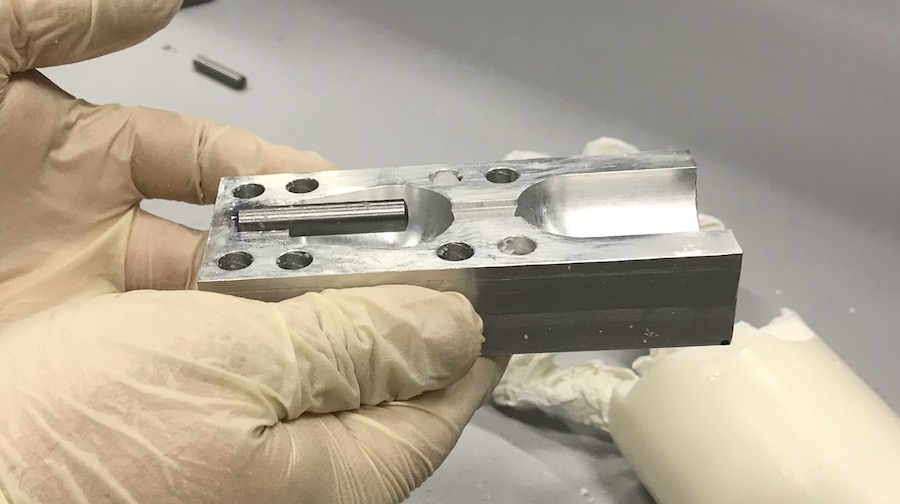
It was clear, at this point, that the opening for the centre pin can not be cleared out perfectly - it's just not possible with a realistic tool geometry and three-axis milling. So, the pin will stick out a bit more, which is perfectly acceptable for now - All aspects of the grip design are estimates, anyway. If it turns out the grip will end up too low like that, I can still grind down the pin to match in what the machine can do there.
Milling, Part 2: Milling
While the actual CNC milling is a rather simple affair (the machine does the work, you "just" have to check it's doing the right thing), setting everything up is not. The whole production process for a mould half is a lot more work:
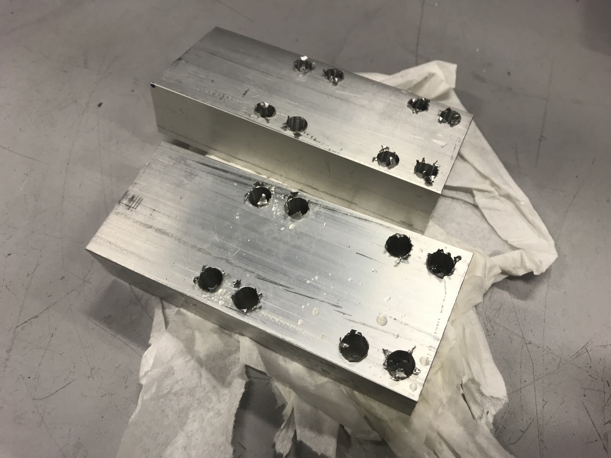
Saw off a piece of stock, leaving it somewhat longer than needed. It would be possible to saw it to fit, theoretically, but with our equipment, that would still leave ugly surfaces at the ends.
Clamp it into the vice in the mill, and position it as vertical as you can get.
Measure its exact position using the measuring system of the machine, then face mill it down a few tenth of a millimetre using the machine's inbuilt capabilities.
Take it out, measure its length, put it back into the vice, but with the other end up. Measure its position, face mill it down to its exact length, again using the inbuilt capabilities of the machine.
Then clamp it back into the vice for the actual CNC milling, using a pair of parallel gauge blocks to have it stand out far enough, but be parallel to the machine's coordinate system.
Measure its exact position using the machine's measuring system
Start the CNC programme, then stand watch while the machine works, actively looking for anything that could potentially be off.
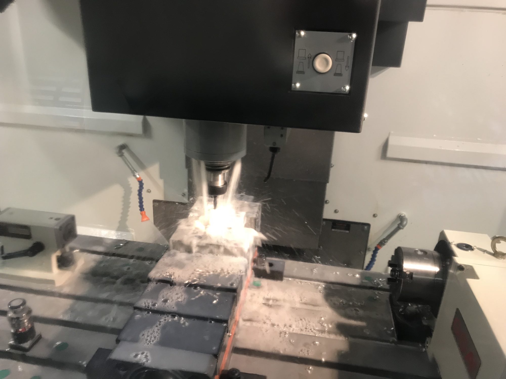
I couldn't take that many photos of the milling process, as it's quite hard to photograph - most of what you see is an inferno of brown water splashing everywhere, through windows that are covered in brown water, too. A few are there, though:
Drilling a hole. The process is is surprisingly unspectacular and quiet.
During the Adaptive Clearing Cycle. Lots and lots of brown water, and a slowly emerging shape.
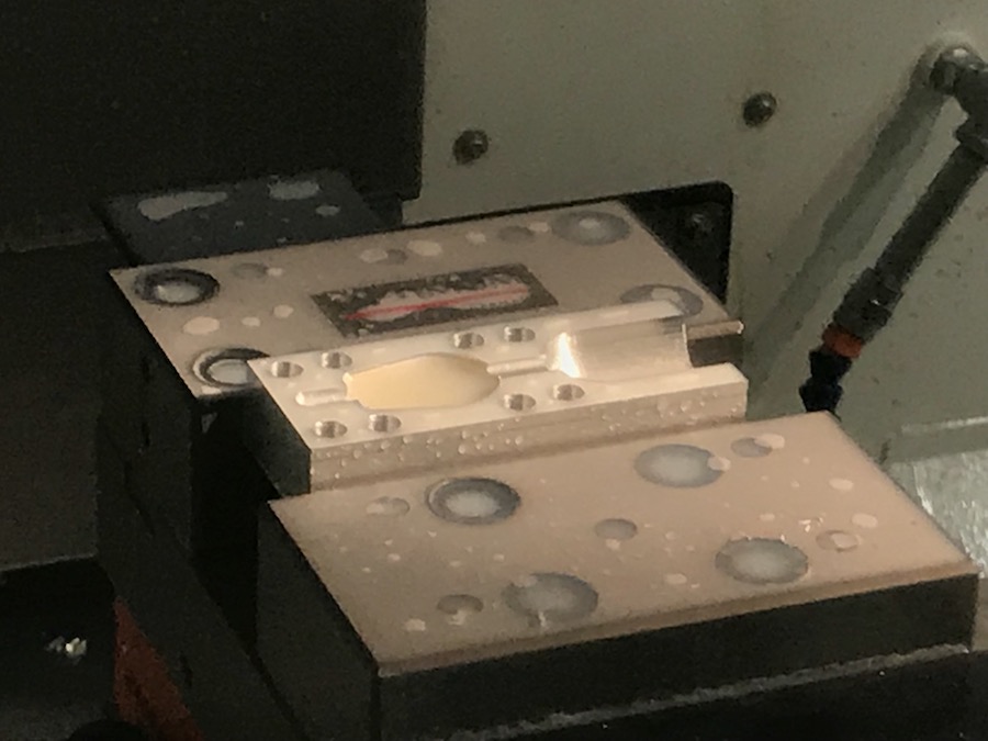
The tool change allows for a somewhat decent photo opportunity. From the distance and through the water covered windows, it already looks like the mould it's set to become.
Finishing cycle of the funnel. You can see the edge of the finished area when it's not behind the tool, and the difference in surface when it's momentarily not submerged in water.
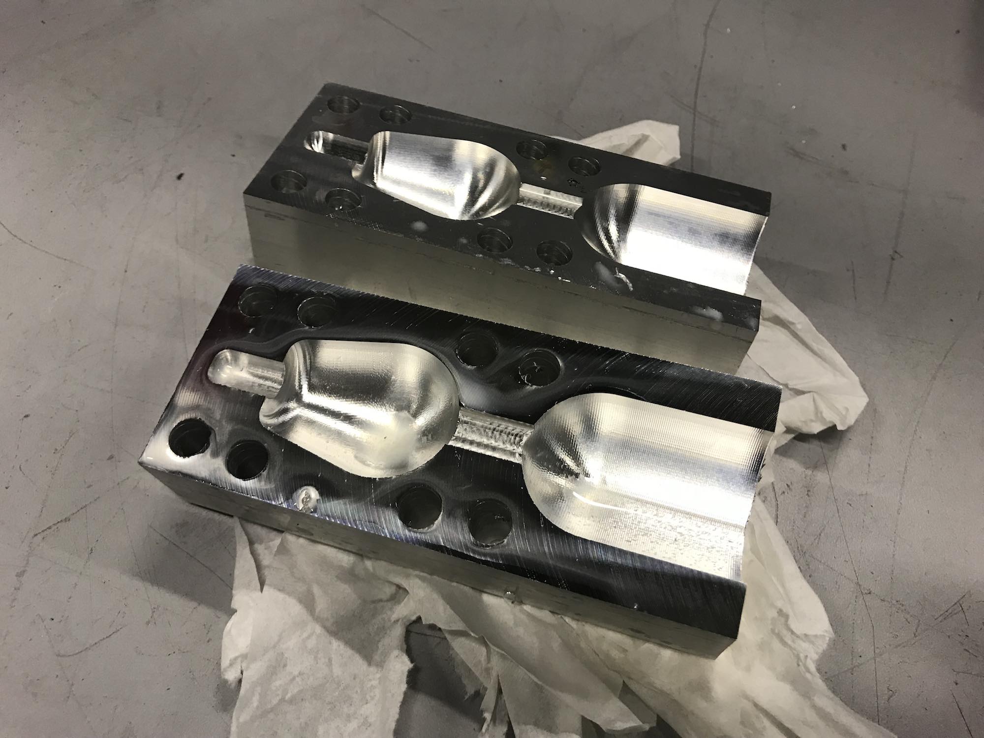
After the last finishing pass, the mould looks shiny, but is still mostly full of water.
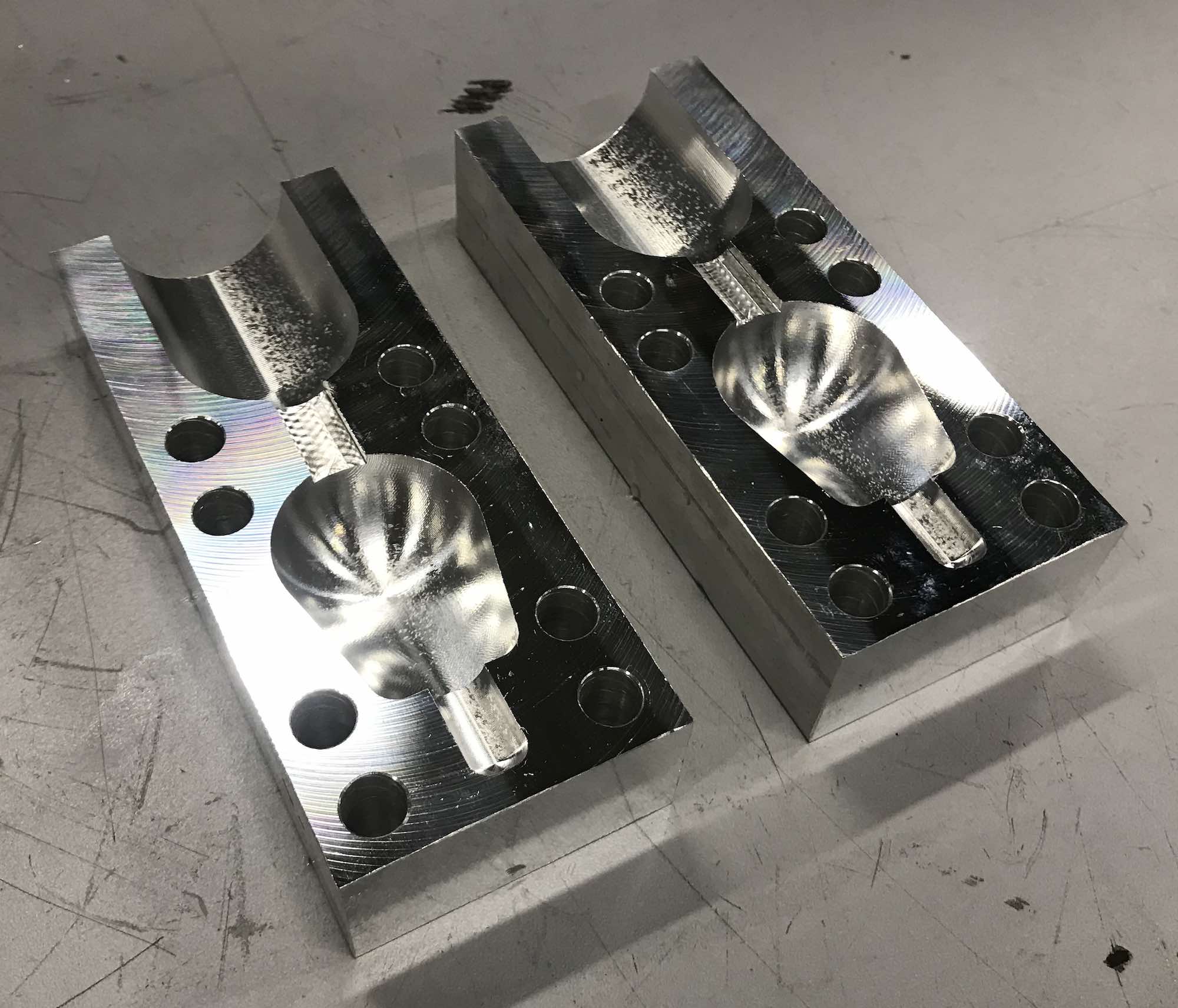
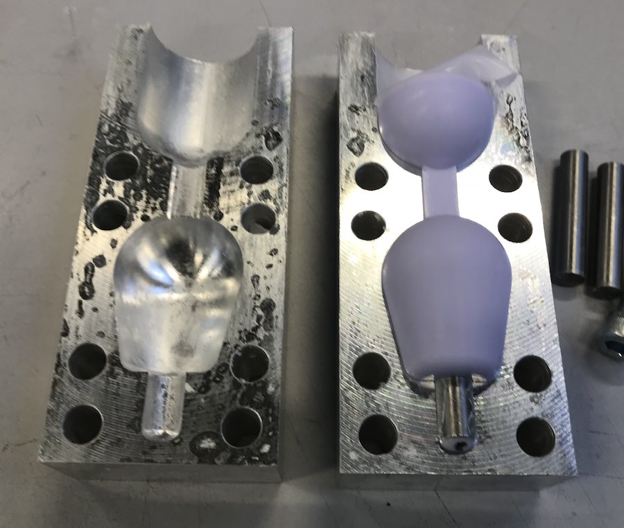
As the mould halves come out of the mill, they are shiny, but their edges are still sharp.
After very careful deburring, the mould halves are ready to use. If the grips made in them turn out to match what I want to have, I might still polish them some more by hand, but right now, that is not necessary.
Casting
Casting is, again, a multi-step process: First, since silicone can stick to aluminium like glue, a separating agent has to be applied. I used the "wax" from a very cheap candle for that, which is a bit hard to apply, but can be smeared on and then made into a thin, nice surface using a paper towel and patience:
Here, the left mould half is covered in wax, the right one is not.
The centre pin, as a third part of the mould, has to be covered, too, of course. As a small advantage, it sticks in place that way:
Also visible here is that the pin is not at the bottom of its opening, as that geometry was impossible to mill. I'm still ignoring that problem for now, if I want to have a shorter hole in the grips I can still grind off from the pin or buy a shorter one.
Then, the mould halves are screwed together, using two additional pins to have them aligned:
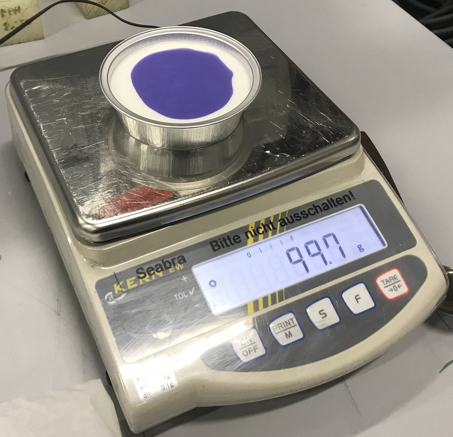
Now, it is time to prepare the silicone, which is made from two components that have to be weighed in and mixed:
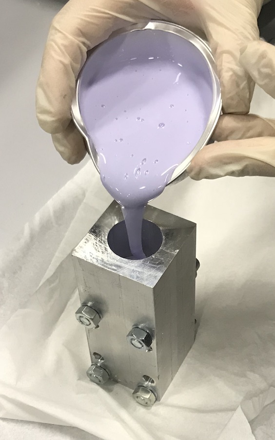
The silicone is then poured into the funnel of the mould, and the mould placed into a small vacuum chamber. Evacuating the vacuum chamber for a few times, then letting air back in transports the silicone from the funnel into the mould.
Result
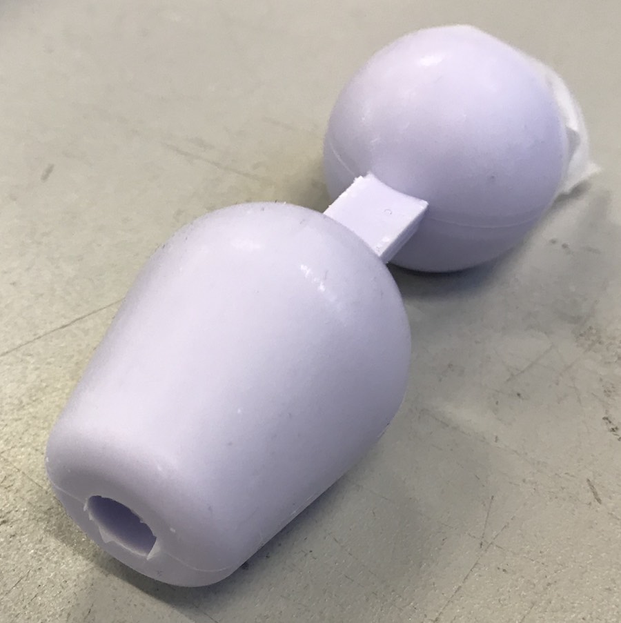
After letting the silicone cure for a few hours (and getting some desperately needed sleep), I opened the mould to find... bubbles. Only a few of them, but more than I would have liked. It should be possible to get them out in future casts (by letting the silicone "cook" for a few minutes at a strong vacuum, so the silicone bubbles take the air with them), but for now, it is usable and looks good enough for me to use. I will decide after some testing if the form is good, or if I need to change it before casting more of them.
A sharp knife easily takes care of the pouring channel, leaving a knob-sized joystick grip: