final project -- weekly assignments -- about me -- fab academy
Week 01: Computer Aided Design
Phase 0: Old friends
A long time ago in a city far, far away... (Roughly 2000 in Munich, OK, not that long ago) The world was still simple. I was at school, doing the rather mad school project of building an enigma machine. Yes, that crypto machine. Not a replica, it didn't look a bit like the original, it was just supposed to work, not to look great. Madness, but I had brought that upon myself.
Building the parts for that more or less required me to get into CNC fabrication. Which was a problem, until I found out that the local model railway club had a small, old CNC mill that could do it. I just needed to draw the parts. Which had to be done either in AutoCAD or in a really bad, cheap knock-off I had access to. I learned to think flat, and to repair what bits of g-code the export could throw at me. The enigma worked, in the end. It broke down right during the final project presentation.
At the uni, my first 3D CAD experience was... hopeless. If you ever have the idea of running Catia on a computer that has been thrown away by another department... Just don't.
A little while later I learned (at another uni) to work with Inventor. It has its quirks, every CAD solution has, but it has served me well even for my first job. It's expensive, though.
Phase 1: The world is flat! - 2D CAD
The gimp
A lot has happened to this one since I last had a look at it. Some years ago, when mostly working with a rather old version of Paint Shop Pro I was annoyed about some file format not opening there and had a look at gimp. To be polite, I was horrified. It did open that file, though.
I was reluctant to pick it back up after that experience. The nice tutorial by our "local" guru ferdi did help, though. Switching the user interface to one-window mode greatly helps against the clutter older versions left on your screen (and against the tool window you need always being obstructed). I played around, then came to actually doing something approaching my final project - an awful graphic of why I find our commercial pick-and-place hard to use:
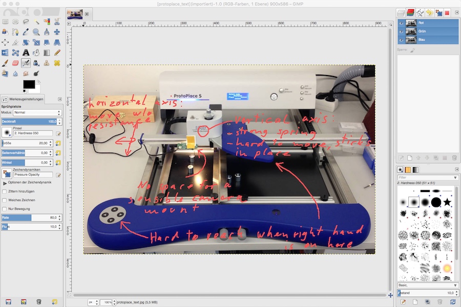
Yes, I know the colours clash. It looks downright awful. I should have used a new layer for scribbling my comments and then changed that... well, too late now. More on the project can be found in the update page on my final project.
On the downside, a few problems remain. Loading gimp is a horribly slow affair, and it still can't handle 16 bits per channel colours. Which is why it can't really handle the output of our digital camera.
In the end, my personal conclusion is that I have found a new tool to use, so it's a good thing I tried.
Why...?!?: Inkscape
Why oh why...? Inkscape could be a really fine tool for (not only) vector drawings. It is not, though. Someone stopped half-way when programming the geometry handling, which is a horrible, unusable mess. Shutting off all options in the 'transformation' subtree lessens the pain, but that's about it.
I did draw a simple overview of my placer project to give it a chance. I'll leave it at that. It is, by far, the worst piece of graphics software I have had to work with yet.
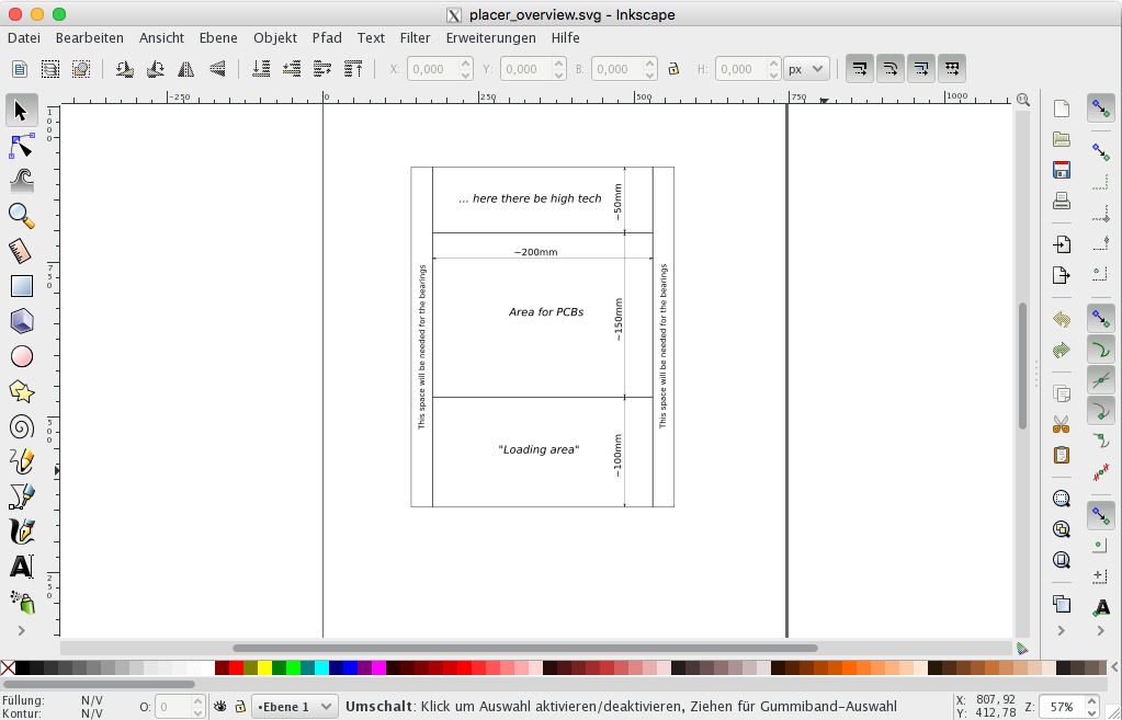
The svg-file is available, of course.
Phase 2: That lump of data over there! - 3D CAD
Work in progress - FreeCAD
FreeCAD has come a long way since I last had my hands on it. It still has some bugs (like lines in sketches on an existing surface vanishing in the rendering) and some inconveniences when coming from other CADs... but it actually works quite well now. That is, you can do a lot of stuff and it works. It even supports my 3D mouse nicely. Development seems to be in continuing progress, so this is one project to keep in mind.
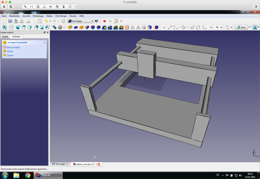
FreeCAD-file. Obviously, that's not much yet, and running into the different-to-inventor UI paradigm they use was no fun. But it works, and it's free enough that you can even tinker with it if you want, which is a cool thing.
One test that is still open is to compile it myself to get 3D mouse support in the mac version.
Big ole Solidworks
Solidworks is the standard CAD solution of our uni, so I will have to have a look into it. I haven't really done anything substantial with it yet, it looks quite different than inventor, though.
The unconventional way: Antimony
I am living in a box. A box full of boxes. Boxes full of... equations.
Antimony (with its own weird association in my head) lives by the principle of building stuff from mathematically defined primitives. While that may sound strange, it is a logical continuation of the theory behind most volumetric CAD solutions, so it's definitely a thing to look at.
A few years ago, triggered by some guy from the 3D-printing horde, I had a look at OpenSCAD, which works in a similar way and has been around for a long, long time. I didn't really like working with OpenSCAD, though, mostly because the sources tend to become a holy mess you can get lost in.
Antimony looks different, and in some ways, it works differently - instead of writing endlessly nested sources by hand, you patch them together from boxes of code in a kind of complicated flow chart. That works quite well and is, at a small scale, a lot less of a mess than OpenSCAD, so it's not a bad thing.
Antimony is a work in progress, though. It's still a little rough around the edges. Also, it is still missing a lot of features that could make it a lot more useful - like exports to CAD formats like STEP, exports to 2D vector formats for drawing output, nesting of files (boxes in boxes!)... Also, the stl output is a mess at the moment. So while it's not useful for anything at the moment, there is hope, though - development has been ongoing.
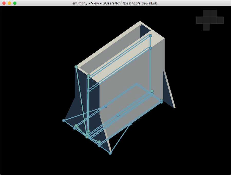
After a little playing around (I made a visual model of a new etching vessel for our lab) I will have a closer look, if only because I like approaches that are different. There is a lot of potential in the whole approach, thinking of automatic model generation, parametric models and other ideas like that.
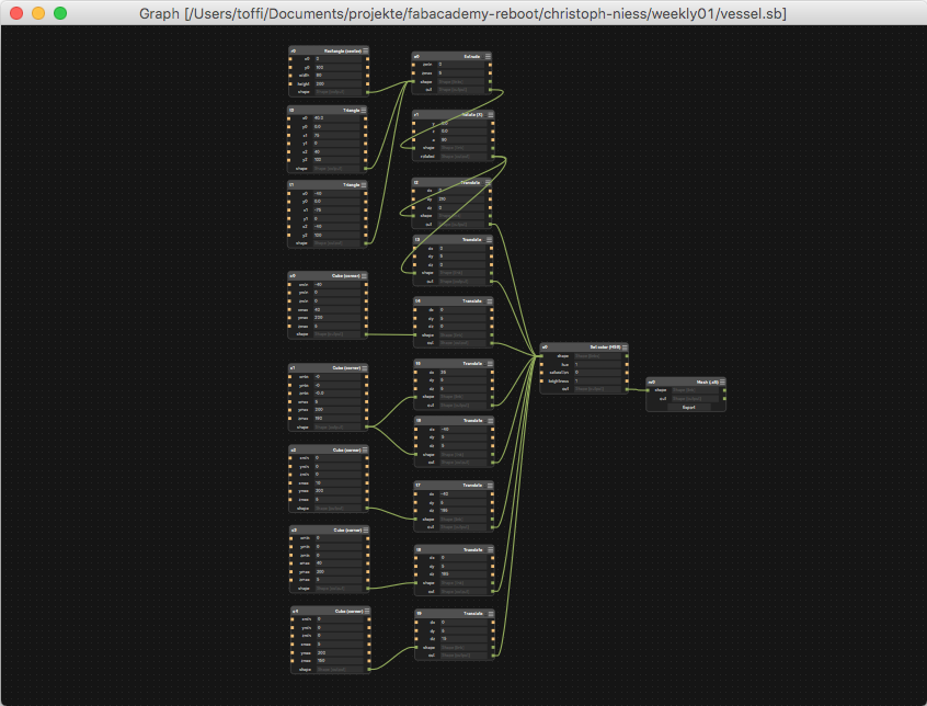
The basic workflow is simple enough: Add (there is a whole menu for that!) in basic form-primitives, either in 2D or in 3D, and fill in their properties (like the length and width of a rectangle, and its position). Then, add in transformations (like the extrusion and the rotation below), and connect the output of one such box to the input(s) of other boxes with green lines. You can do a lot of fun, parametric design here, as you can also connect the parameters of the boxes - It should be easily possible to make a fully parametric design that way, though probably only by getting creative with some transformation boxes.
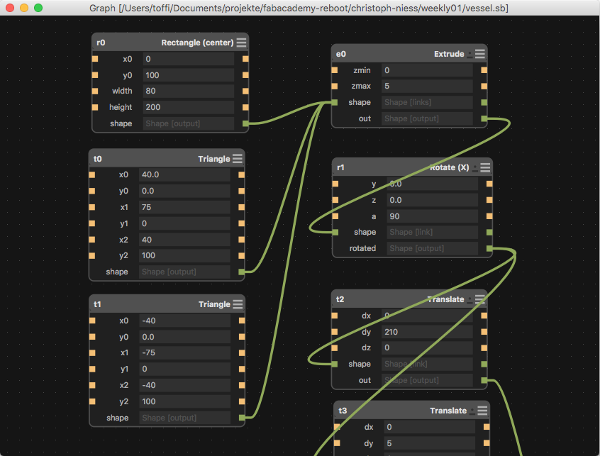
This part describes the side plates (front left in the last image), which is why the final result of its transformation is fed into two "Translate"-boxes - One for each side of the vessel.
A thing as whole can get pretty big, and you can sadly not package parts of it into boxes yet (at least not that easily). The etching vessel, in its whole, nonparametric glory, is already quite a bunch of boxes.
The result renders to a second window, and while looking unimpressive, it's still an interesting approach to doing things.
As the etching vessel is supposed to be made from laser cut parts, I will have to do the actual work in a different piece of software, though. Maybe TikZ.
Not That Bad: OpenSCAD
Like Antomony, OpenSCAD is one of those absolute oddballs of the CAD world, as you actually program your 3D model. You do that by defining, in a really mathematical way, how it should be built up from basic forms ("primitives"). Which is about the least intuitive way possible for most people.
This unconventional approach has its advantages, though. Programming a fully parametric part that can be altered to fit a new size by changing a value is more of a by-product than a special feature - We're programming the model, anyway, so using variables is just the normal way of life. It's not even special to have parts of your model appear or disappear depending on a value (Think of the number of pins on an IC...).
As of now (2018), I am actively using OpenSCAD to make 3D models of electronic components for my parts library for KiCad. Most of those models would be easily available from the original parts' manufacturers, but I want to have an open source parts library that I can actually share, and that is something most (if not all) manufacturers explicitly forbid.
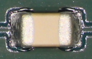
As a small run-through of making a model in OpenSCAD, I made an extremely primitive model of an SMD capacitor - Right now, it doesn't matter which case size. To start out, we think of a capacitor, and start hacking it to pieces dividing it into simple part-forms:
- A middle part that is basically a yellow block - we will ignore any rounded edges for now
- Two metallic end caps that are, essentially, again only blocks. Much more rounded, but we will ignore that again
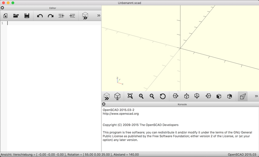
To begin with, we fire up OpenSCAD (or any text editor) and make a new file:
To start out, we write down the basic measurements of your capacitor (taken from its datasheet) and drop them into variables:
overall_length = 1.05;
contact_length = 0.3;
width = 0.55;
height = 0.55;
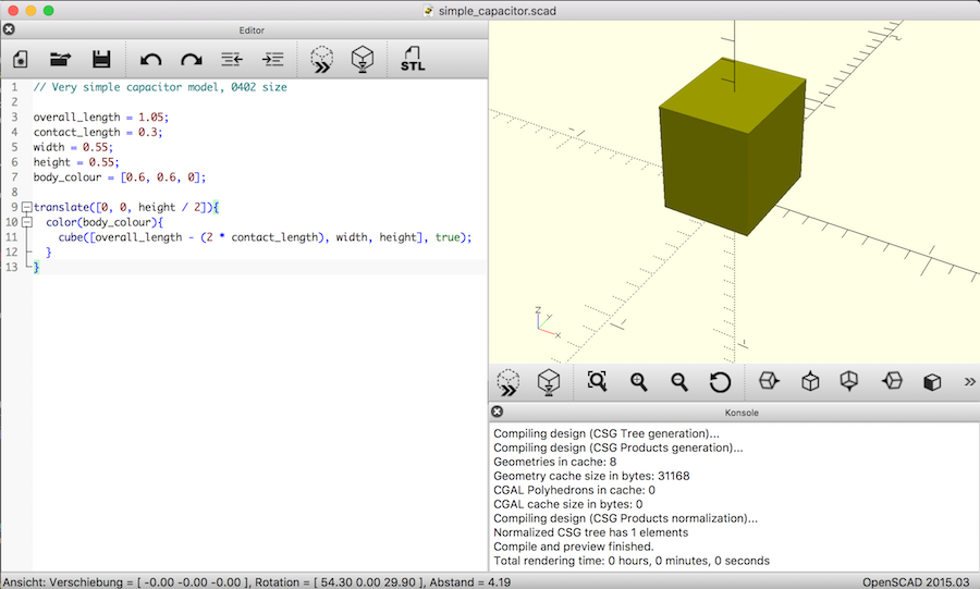
We'll begin the actual model with the central part, the yellow block. To OpenSCAD, it is a "cube": cube([overall_length - ( 2 * contact_length ), width, height], true);. This cube is now fully parametric, but it is still "colourless" and sits around the coordinate origin, which is less nice, so we change that. First, the colour. We define that as a variable, too (in RGB percentage values), so we can later change it if our preferred capacitors turn out to be white: body_colour = [0.6, 0.6, 0];, then we apply it to our part: color(body_colour){cube(...);} with the cube we already did. Then, we move our cube so it sits above the X/Y-Plane: translate([0, 0, height / 2]){color(body_colour){cube(...);}}. The almighty OpenSCAD cheat sheet helps if you want the details of all those commands. Our OpenSCAD window might look like this now:
A good next step would be the contacts. They are just cubes as well, in a different colour, and moved not only upwards but also to the sides:
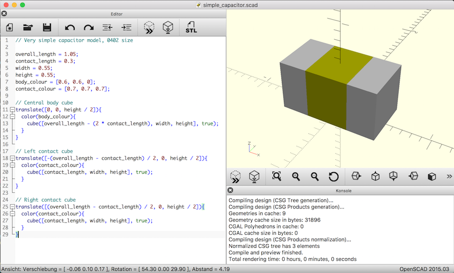
OpenSCAD joins those three cubes into one model by itself, the clean way would be to put them into one union(){}, though. If you want to play with this very simple model, download it and have fun.
My workflow for putting a model into KiCad would now be to open it in FreeCAD (which is a disaster, but can import OpenSCAD-files) and export them to STEP there. I did that with a somewhat less primitive model of the same capacitor, and rendered a view of it in KiCad's raytracer:
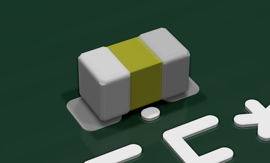
The "holes" in the rounded edges are due to one of the idiosyncracies in how OpenSCAD translates from a mathematically defined model to a heap of triangles. They can be fixed by changing the circle-to-polygon settings... Which is what I plan to do when I go over that model to get rid of the small offsets at the rounded edges. That will be some unfunny work, those are necessary right now to circumvent a bug in FreeCAD's core.
final project -- weekly assignments -- about me -- fab academy
