final project -- about me -- weekly assignments -- fab academy
Plastic Fantastic: Clock Mechanics
An electromechanical clock doesn't really need that much, mechanically. The way I wanted to build it, with wheels driven by geared motors to show the digits, can be divided down into four identical units, one for each digit. Drawing one part in CAD is less work than drawing four, and printing four identical parts is simpler than printing four different parts, so I decided immediately to build the clock from four identical units.
Coming up With a Design
The first important step from the general idea to drawing actual parts was to determine the size of the numbers on the wheels. That size is kind of a building block for the rest of the clock, as it directly determines the smallest possible wheel diameter, and a sensible wheel width. With the length of the motors given, I didn't want to be too small there, as the distance between the individual digits can't be smaller than the length of a motor. With the motors getting in at roughly 44mm, I estimated that 30mm high numbers might work OK (not making the wheels way too large, but also not looking totally ridiculous). Also, at that size, the numbers should print OK.
With that size fixed I fired up inventor, and started with a decagon. I set the edge length to 40mm to have some space for rounding the edged of the complete wheel, and still have 30mm numbers on the faces:
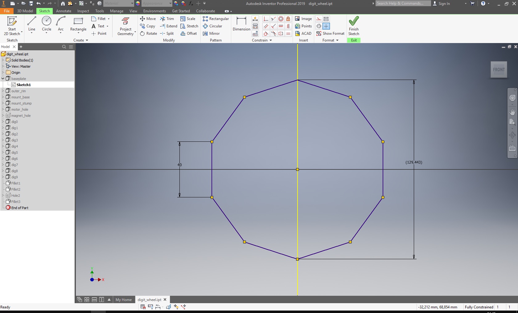
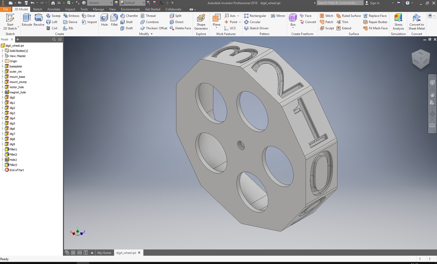
Since I wanted to have hollow wheels with the motors inside, I first made a plate of that shape, then added a wall around it, aiming for 30mm width - A number of 30mm height should easily fit into that, and putting 40x30mm openings into the front plate should look good. Since the wheels are quite large and the bearings of the geared motors are quite bad, I wanted to have the wheels hanging from a ball bearing (it's just the simplest to adapt a printed part to, since it doesn't require any really smooth surfaces). 608-size ball bearings are about the cheapest stuff you can get, so I planned on them, even though they are way too large for the load and easily weigh more than a wheel. The resulting wheel is still a relatively simple part, with large holes not for weight, but for some access to the parts behind it:
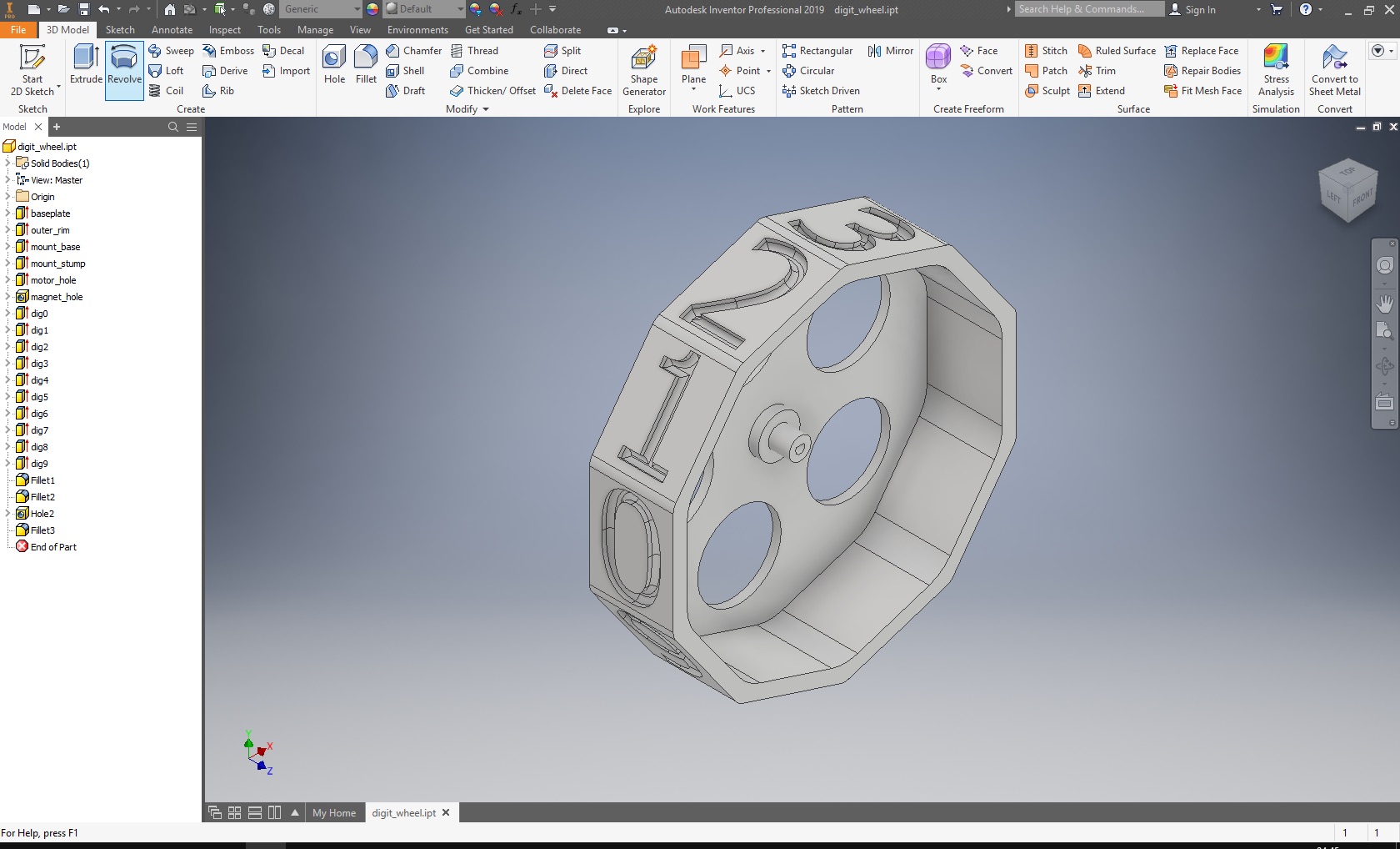
The magnet for the encoder also needed somewhere to go, so I added in a small hole at the other side. It is sized so the magnets will easily slide in, but stand out a bit to be closer to the sensor:
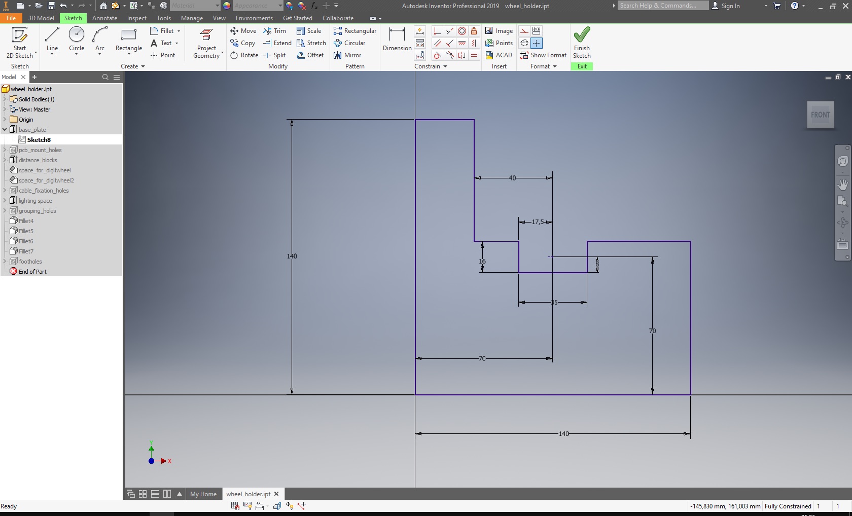
At this point, I needed to get some further measurements right, so I could draw the frames keeping the wheels in place. The trusty high-tech solution for this is a sketch:
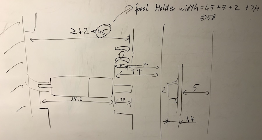
It's probably not readable for anyone, but it allowed me to determine the necessary width of the frame pieces (and, thus, the distance between the digits) to be 58mm, so between the "windows" of the front panel, there will be almost a window width of unused space. Not as nice as I would have liked it, but I can't easily shorten the motors...
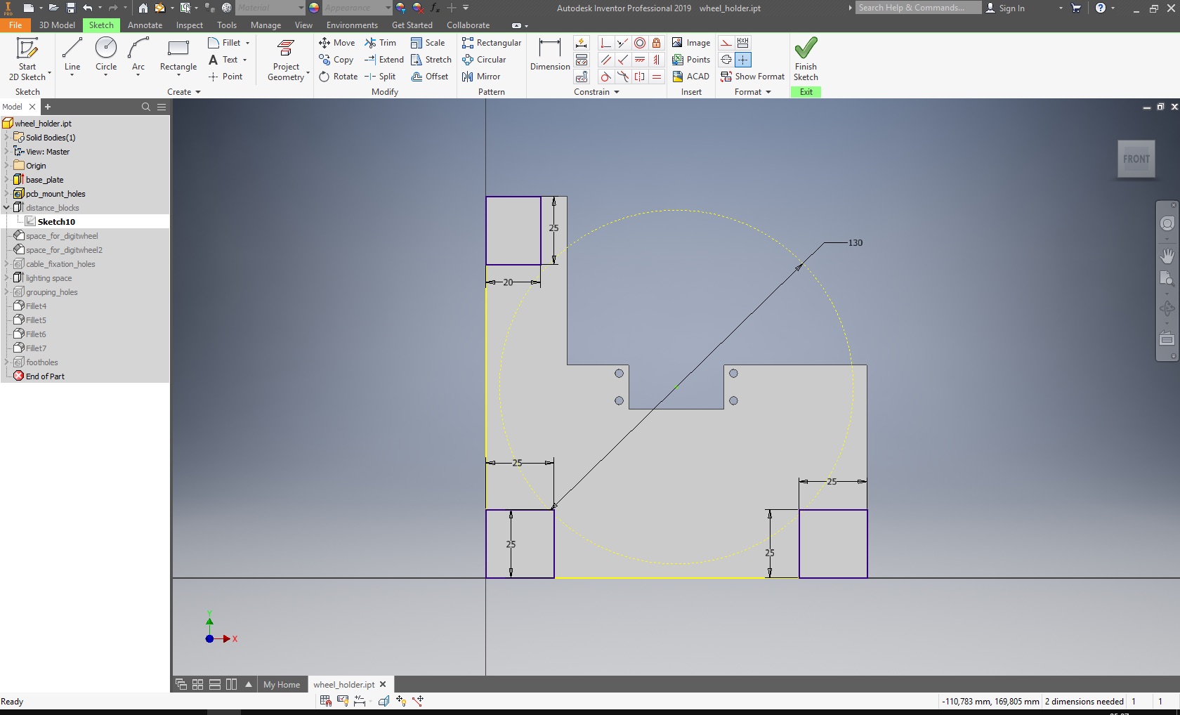
The frame parts are simple parts to begin with, again. With the wheel diameter fixed at almost 130mm, I decided to make the clock 140mm high and deep, so there is little space wasted around the wheels. The wheel axis is in the middle, so the motorboard has to be fixed there, too, leading to a cutout. Then, I don't want to have that huge bottom surface to print (it takes time), so I shaved off material where I thought I could get away with it:
In that image, the front of the clock is at the bottom - with the coordinate system right for printing without having to flip the parts first, inventor just puts it like that, and I can't pretend to care...
The frame parts cannot be full material, of course, as all the moving parts are in them. So, I drew them as a plate, too, and added posts to keep those plates at a distance. Drawing in a circle for what the wheel size will be helps a lot:
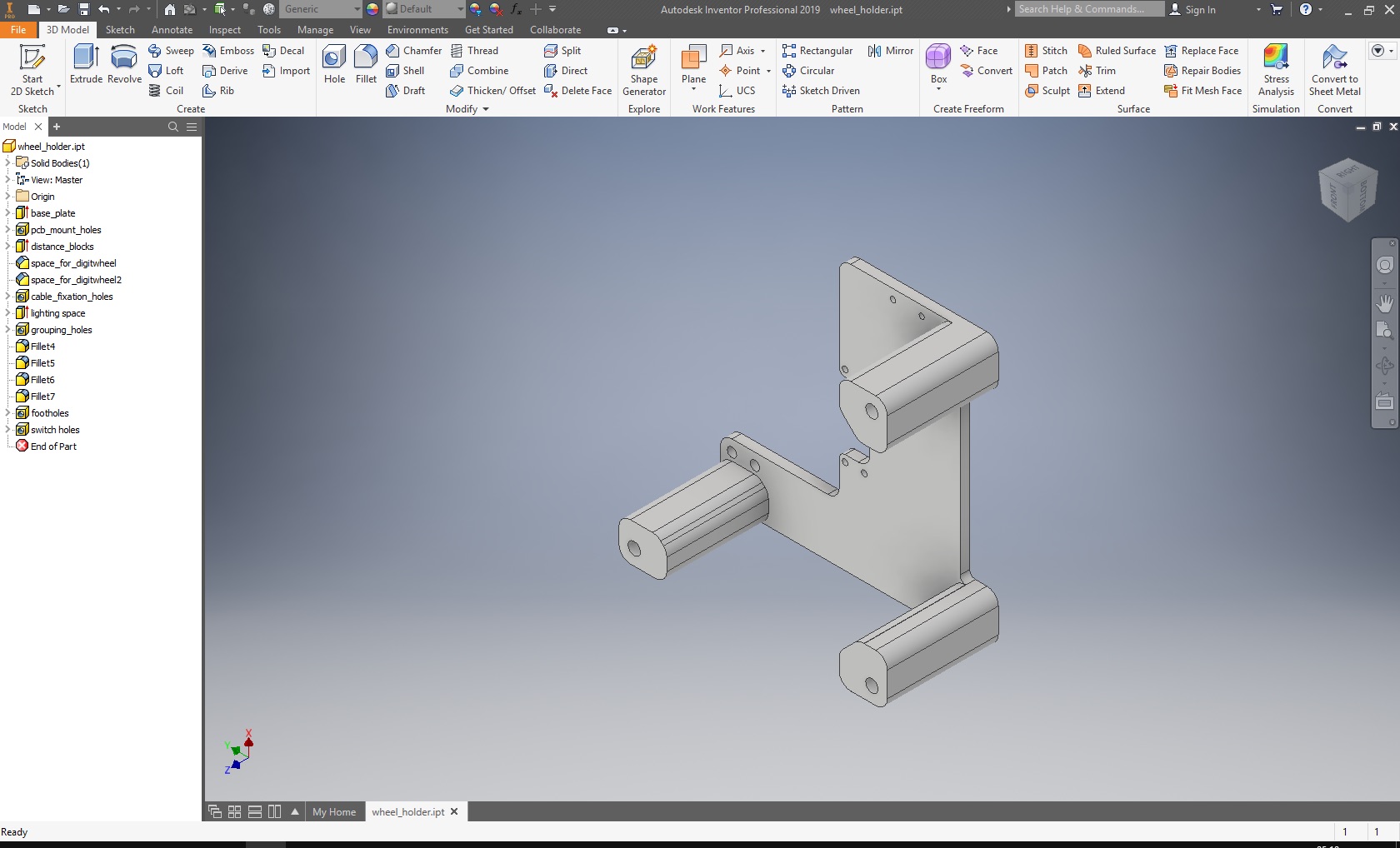
There are actually a whole lot of holes in the frame parts, for screwing them together, screwing in the feet, putting in zip ties to mount the cables, ... So, the completed part is more like a piece of cheese:
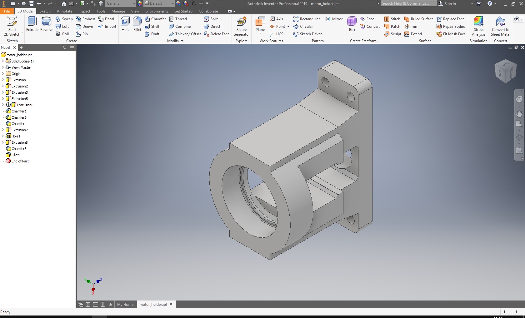
The last interesting part were the motor holders. They are made to (rather loosely) fix the motors in place, but not restrict them too much - All the little imprecisions of manufacturing can add up, so I wanted to give the motors a little bit of space to move before stuff breaks just in case.
There is also a center frame part (which is a normal frame part with the front filled in and two 8.5mm holes to mount the front panel) and an end plate - The last frame part doesn't need the distance posts, so I omitted them.
Production
The resulting parts were exported to stl and printed on the ultimakers of the Technical Center for Thermal and Mechanical Process Engineering:
The front plate, which is made not to be an enclosure, but a design element, was cut from aluminium during BZZZZZZZZZT Week.
Assembly
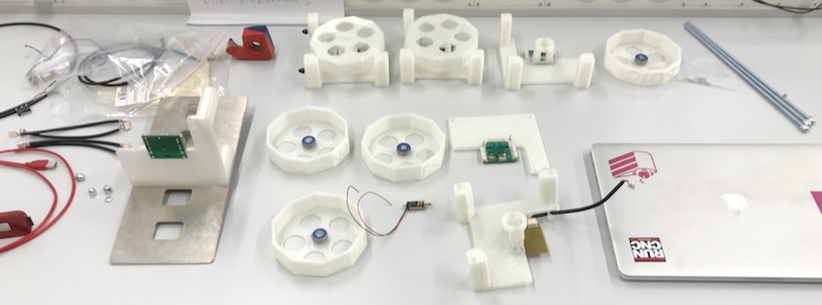
Clock parts:
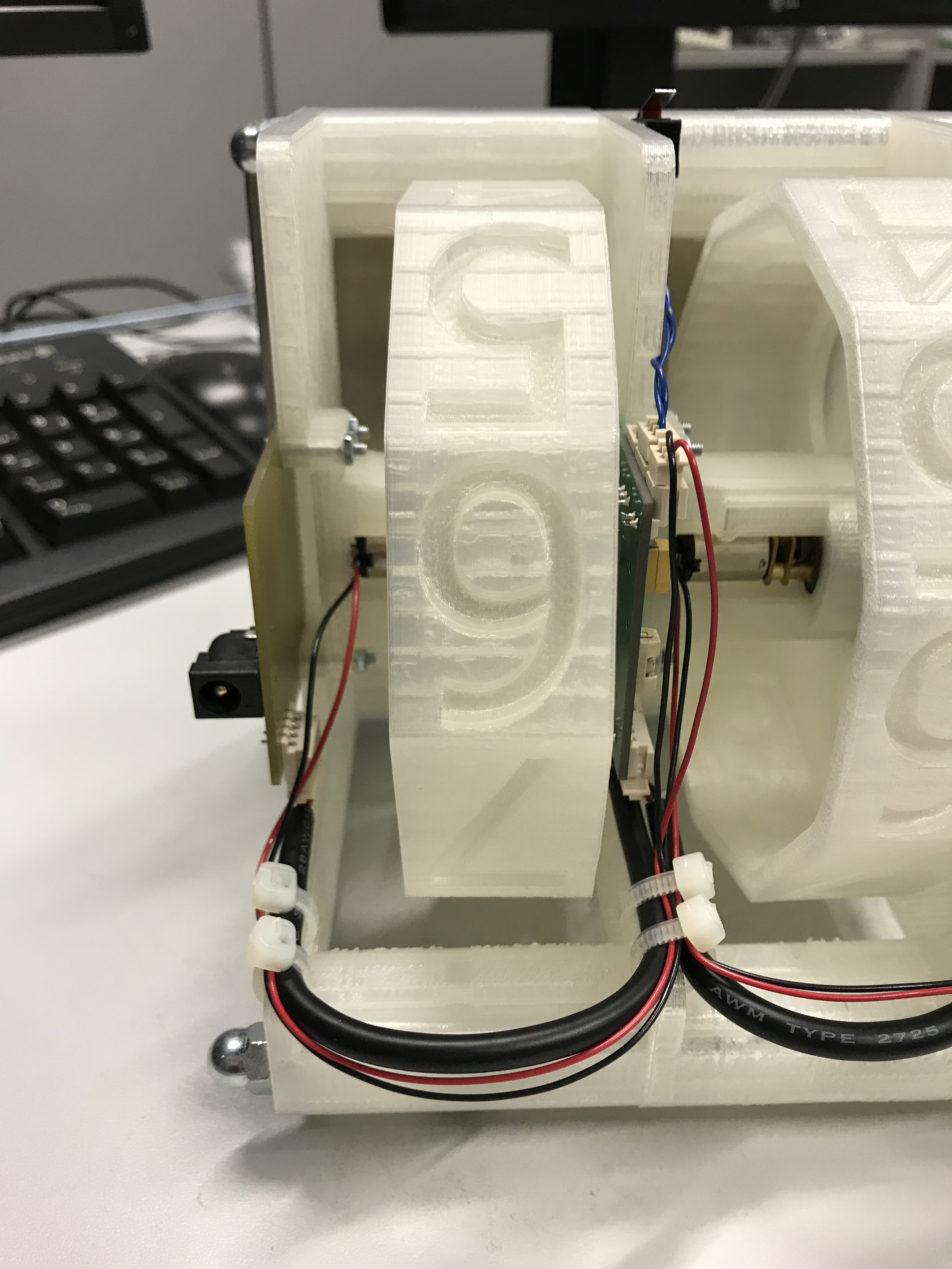
The assembly around the minutes wheel, with the power input board on the left, and a motor board driving the wheel on the right:
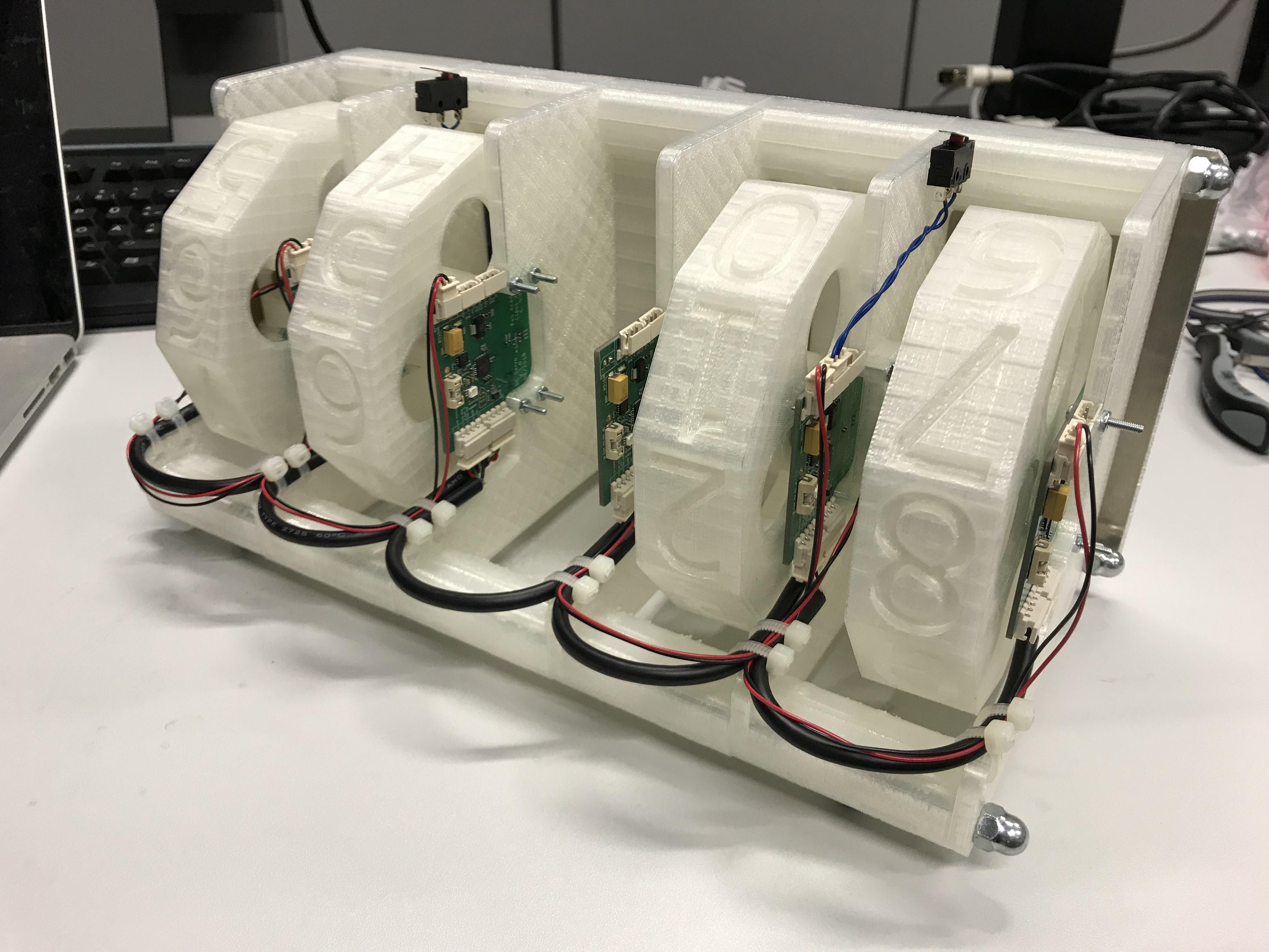
The complete clock from the back:
final project -- about me -- weekly assignments -- fab academy
