Week 3: Computer-Controlled Cutting
Download this week's code
- Press-and-fit test piece FUSION
- Press-and-fit test piece DXF
- Vinyl-cut face sticker fusion
- Vinyl-cut face sticker DXF
- Press-and-fit face FUSION
- Press-and-fit face DXF
Little things
Because I am inbetween backup solutions right now, and it is only my Fab Academy work that is not backed up, I started doing an rsync backup to a USB stick using this command:
rsync -av --modify-window=1 SOURCE DESTINATION
Note: all DXF files exported by Fusion 360 cannot be read by our laser-cutting software. A workaround is to open it in Adobe Illustrator and re-export it as a DXF.
Concept
I decided that I would base the week's project off of pictures of my sons' heads. I would find at least one image with a good outline. It would be used to create a vinyl sticker on the vinyl cutter, and I would add slots to it to create a press-and-fit construction piece.
Manipulating the source images
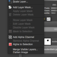
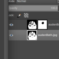
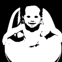
I scoured images of my children for a good face with a clear outline. I then used Gimp thresholds to give a clearer outline. I used layers and a mask to adjust different thresholds for the facial features than for the outline of the head, because I wasn't happy with the results when I applied the threshold tool to the entire image. I duplicated the image into a second layer. Then, in the layers menu I used "add layer mask", and then used the lasso around the facial features of my son, and used the fill tool to fill that with black. This created a "window" through which the other layer could be seen, affecting only the facial features. I could then use the Threshold tool in Colors on each layer separately, until I had a threshold image that had good facial features but also a good head outline. I then exported to a png.
CAD'ing the 2D cutting outlines
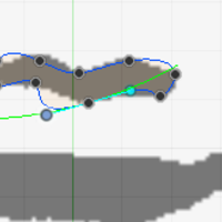
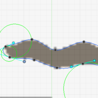
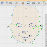
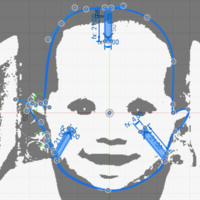
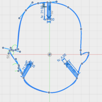
The strategy is to import the image into Fusion 360 on a canvas, and then use the spline tool to trace around the edges defined by the threshold effect on the image. Then to add the slots based on parameters, then export that as a DXF. I already know how to do parametric stuff in Fusion 360, so I will do that rather than learn Inkscape or Adobe Illustrator (though I know that I should probably spend some time learning those tools).
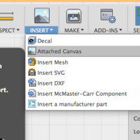
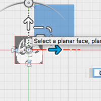
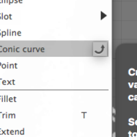
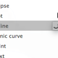
I attached the image to a canvas, and then resized so that the head is about 100mm across, which seems like a nice size. I knew I was going to use splines, but I tried conic curves just to see how the tool behaved. It didn't do at all what I wanted. I also added the spline tool to the toolbar using the little curvy arrow icon that pops up beside it in the menu.
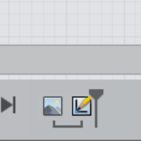
When I went to create the slots the canvas image kept disappearing. I found the solution here, it was a timeline problem. I dragged the canvas before the sketch to make it appear when I was editing the sketch.
This sketch was then exported to a DXF by right-clicking on the sketch in the browser and selecting "Export as DXF". This will be a vinyl-cut sticker.
CAD'ing the 3D press-and-fit part
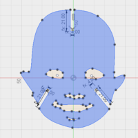
The goal was now to take the outline for the vinyl sticker and cut slots into it. I will add slots where the shape and features of the face allow for it, and I am hoping that the strange geometry of the slot placement will make for interesting shapes when the pieces are finally cut.
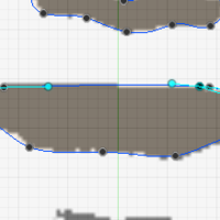
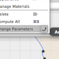
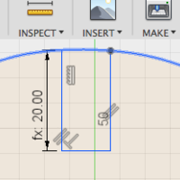
The slots were created using lines, set with constraints and parameters to hopefully allow them to move and resize as needed. After creating the slots off of the splines I could not figure out how to delete the spline segment between the edges of the slot. After much Googling it appears that the answer is "splines don't work that way". I resolved to start again by starting a new sketch over the existing sketch, beginning with the slots, and then retracing the splines between the slots. I tried creating a single slot model and then copying and rotating it, and when that happened some of the constraints disappeared. Googling for solutions came up with "the constraints must have been dependent on absolute-position in the sketch", which my constraints absolutely weren't. Eff it, I drew each and every slot separately in the proper orientation with the proper constraints and parameters. I added Change Parameters to the toolbar for quick reference by clicking that curvy arrow thing, and changed the slot parameters to make sure that they were changing properly. They changed orientation a little, but not so much to both me. I know that this may be a problem later on with other designs.
I now know that this could have been done differently. Trace the entire image with splines, add the notches, then extrude the shape and create a new sketch from that extruded face. Apply the chamfers to the 3D edges, then create a sketch from the face and export to DXF. Tada!
Laser cutting
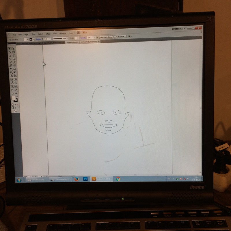
To get the Fusion sketch to the laser cutter, right-click on the sketch, and export as DXF. This DXF file cannot be read by the computer attached to the laser cutter, so a workaround is to import it into Adobe Illustrator, and re-export it as a DXF.
The slots in the face piece are parametric, and so I made a piece to test the slot widths, based on similar pieces that I had seen come up in and around class. It is a basic shape with 5 slots, ranging from 0.2mm less than the width of the cardboard, to 0.2mm greater than the width of the cardboard. This didn't create a tight enough fit, so I changed it to range from -0.7mm to -0.3mm. After testing the pieces, -0.6mm made a nice tight fit.
The press-fit test pieces had issues with the engraved text. Even though it was "expanded" in Fusion 360, it did not join the nodes, so the laser-cutter software did not see the spaces as enclosed. Use the option "unite lines" from the Tools menu. Frank warned that this can be a problem for very detailed designs.
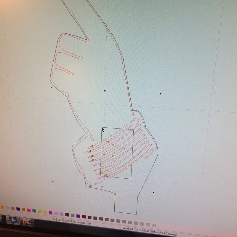
The dimensions were screwed up in the import. For the press-fit piece, this was fixed by measuring the line along the horizontal of the piece, and resizing the work in LaserCut5.3. For the baby head, splines cannot be measured in this way. I created co-incident parallel lines with the outermost points of the design, and measured the distance between using Inspect - Measure, and then resized the piece in LaserCut5.3 that way. I calculated that the piece should be shrunk to 44.82%, but I have not confirmed this with multiple files to be sure that this is always the case.
A solution to the DFX-resizing problem: Resizing the mis-sized DFX design in the laser-cutter software is not too much of a problem if your design as a single long edge that you can measure from your original design. If it doesn't, like if it's curvy, then it is difficult to find the exact dimensions of your sketch. After my day of cutting I came up with another solution, which I have not tested. In Fusion 360, or whatever your design programme is, put a single square around your entire sketch, with simple, known, dimensions. In the LaserCut5.3 software, you can then resize the entire design to the size of that original square, and then delete the square when you want to cut.
I have since been told that you can set the DXF units in Fusion 360. I don't know how to do this but I will investigate.
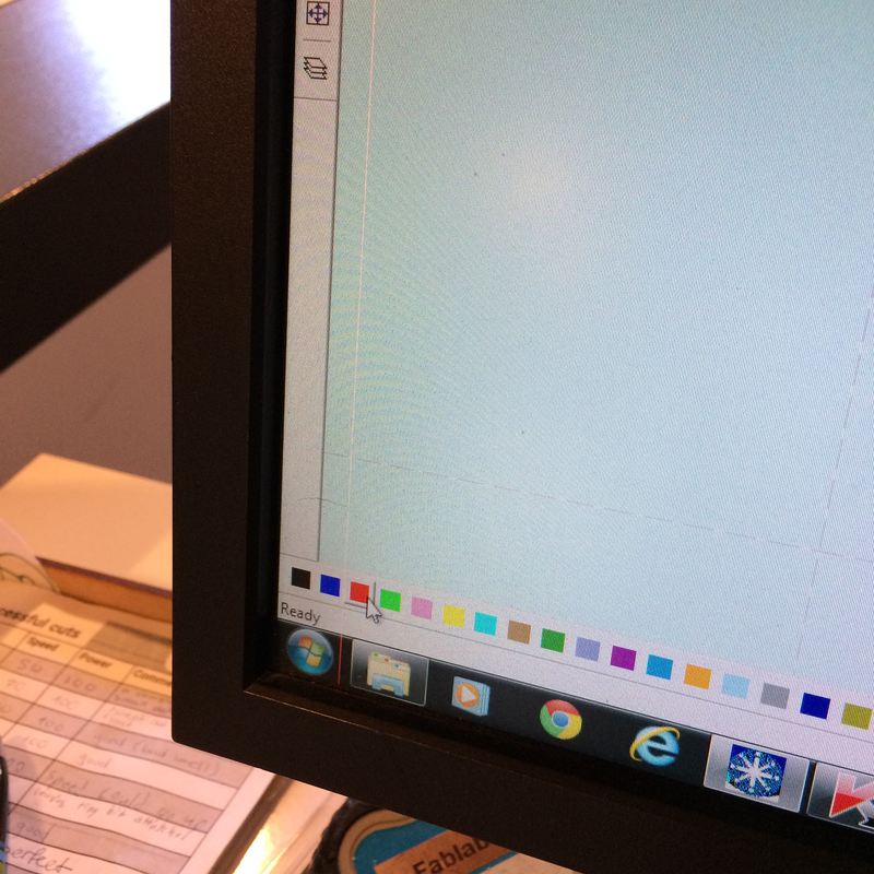
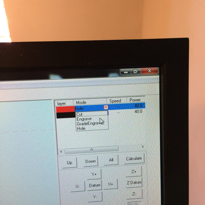
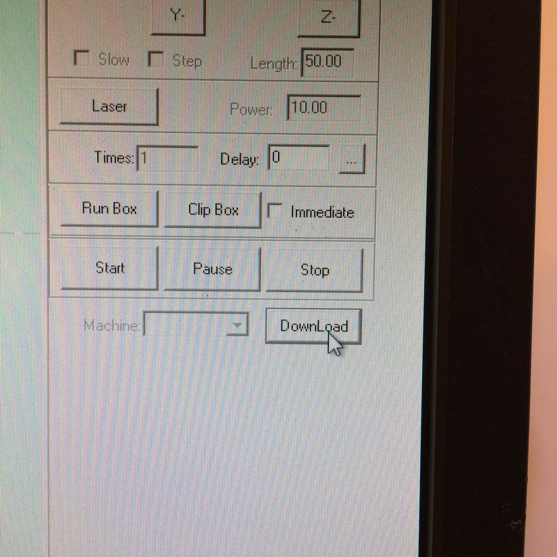
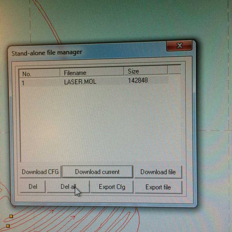
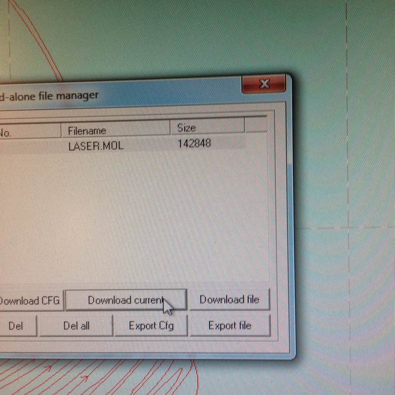
After resizing the enormous design. To have different lines in the design behave differently in the cutter, select them with the mouse cursor, select a colour at the palette at the bottom of the window, then in the floating window, double-click on that colour and select speed and power (and other settings, if you want to). To change the order of the cutting, select one of the colours in that floating window and click Up or Down to move its position in the cutting order. Then Download the design. Click Del All to clear the previous design from the machine's memory. Then Download to send it to the laser cutter. To turn the cutter on, turn the key, press the green "on" switch, and when you are ready to cut turn on the air circulation machine under the computer (green switch), and turn the laser-head switch to on. Place the laser head by clicking the arrow keys on the laser cutter. When it's placed well, press Test to make sure that it is cutting where you want it to. Then CUT!
When testing cutting the piece, I had several issues with engraving and with the cutting curves being wavy. These are a summary of the results:
- #2: cut speed 100 power 90. Engraving speed 400 power 20.
- #4: cut speed 80 power 70. Engraving speed 400 power 20. Splines cut slow.
- #5: cut speed 50 power 90. Engraving speed 400 power 20. Engraving fainter on new cardboard.
- #6: cut speed 100 power 85. Engraving speed 400 power 20. Splines wavy. Engrave still faint.
- #7: cut speed 80 power 40. Engraving speed 400 power 25. Splines cut slow. Did not cut through.
- #8: cut speed 100 power 85. Engraving speed 400 power 30. Splines wobbly. Otherwise it's fine.
Then I cut a lot and built!
An update on how to use the laser cutter
Emma requested that I provide more detail about how to use the machine and the software. I did some laser-cutting again for the machine-building week, so I'm using that as the source for these instructions.
Our laser is a BRM Laser 120160. Here it is:
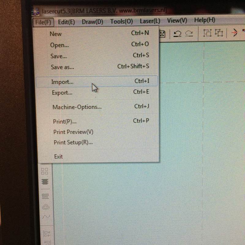
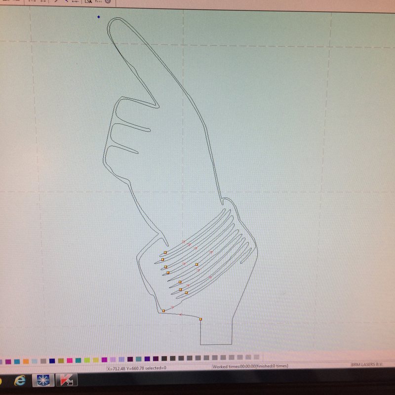
Load your vectors (illustrator or DXF) into the LaserCut5.3 software by selecting "import" in the menu. Depending on how you generated the vectors, you may need to select all and choose "unite lines" in the menu to make them contiguous shapes.
To choose how certain parts of your design are cut, select them with the mouse, then click a colour along the bottom of the window, and in the top-right, you can select what kind of cut that colour will be made in, and what the speed and strength is. And click the Up and Down buttons to affect the toolpath order.
To get the commands to the laser cutter, click DownLoad, then replace the existing files in the machine's buffer with "Del all", and then "Download current".
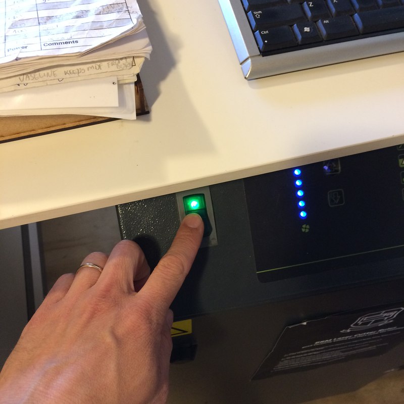
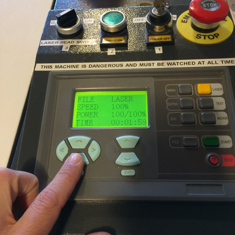
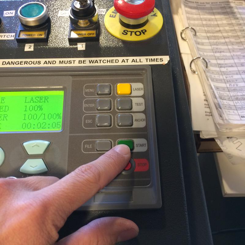
Enable the machine, turn it on, turn on the exhaust system:
Move the head where you want with the arrow keys on the machine. If that doesn't respond, press ESC, and when you're ready, press START. Also (not shown here), press TEST to have the machine trace out the pattern so you can make sure that the cut will be where you want it to be. Also not shown here, use the wooden spacer provided with the machine to make sure that the laser head is the right height above the cutting material. Rotate the collar to loosen it, place it so that it is just touching the spacer, then retighten.
Vinyl cutting
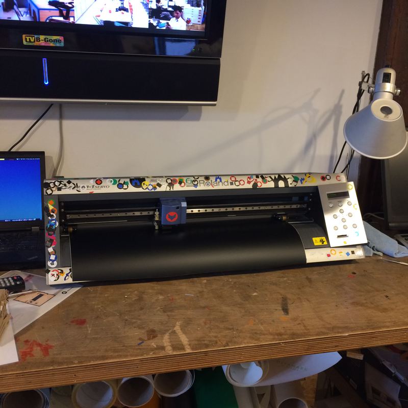
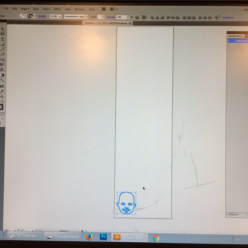
The vinyl cutter that we have is a Roland GX-24. Open your DXF file in Adobe Illustrator on the attached computer. Resize it so it fits nice, and move it to the bottom left of the page.
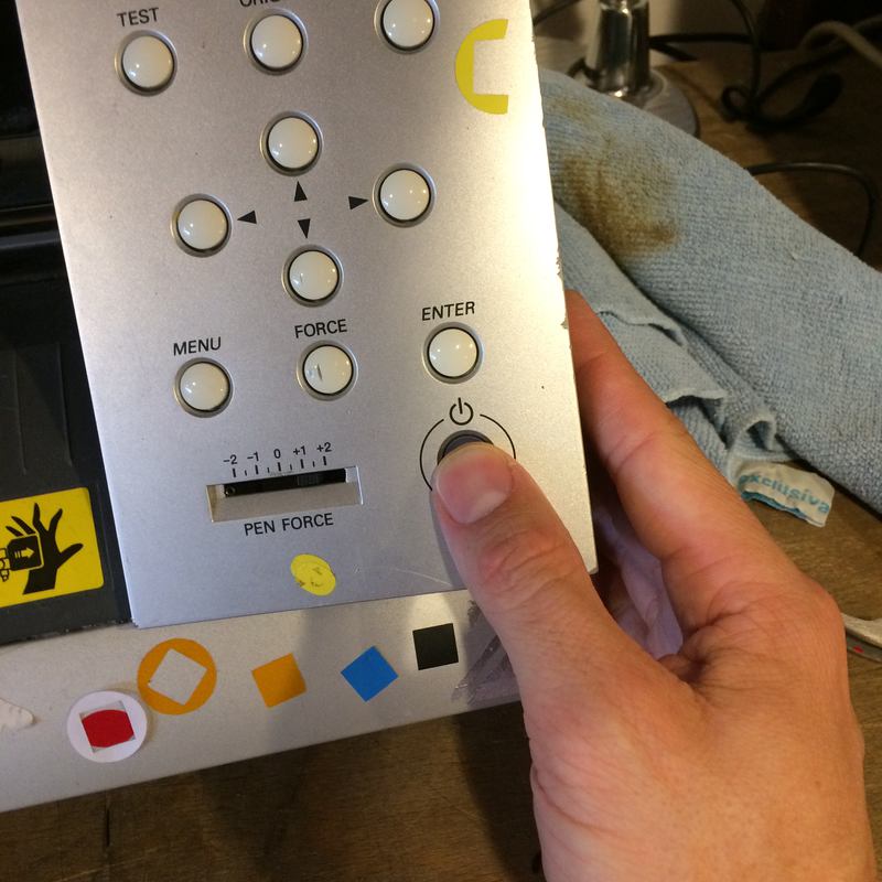
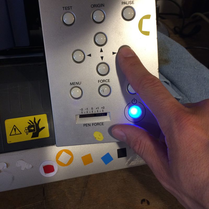
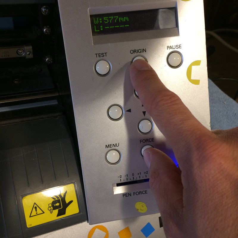
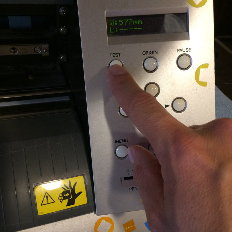
Turn the cutter on. Unlock the clamp at the back of the machine, insert your material, relock the clamp. Press Menu and set the material type to Roll (or whatever you're using). Use the arrow keys on the machine to set the cutting head, and press Origin to set the machine's origin. Press the Test button to print a test cut, and examine the cut to see if you like the way that it cut (that means, that it cut through the material, not the backing, and the cut was clean). If you didn't, press the Menu button and navigate to Condition (obvious, right?) to change the speed and force. I tested a bunch of speeds and forces until I settled on 120 g and 5 cm/s.
If the sticker is particularly large or complicated, you can first transfer it to a weak adhesive material, peel away the negative material, and then apply the sticker to your desired surface. I did not do this. My sticker was small and was able to be easily trasnferred.
Et voila!

